element14 Community
element14 Community
    Register Log In
  • Site
  • Search
  • Log In Register
  • About Us
  • Community Hub
    Community Hub
    • What's New on element14
    • Feedback and Support
    • Benefits of Membership
    • Personal Blogs
    • Members Area
    • Achievement Levels
  • Learn
    Learn
    • Ask an Expert
    • eBooks
    • element14 presents
    • Learning Center
    • Tech Spotlight
    • STEM Academy
    • Webinars, Training and Events
    • Learning Groups
  • Technologies
    Technologies
    • 3D Printing
    • FPGA
    • Industrial Automation
    • Internet of Things
    • Power & Energy
    • Sensors
    • Technology Groups
  • Challenges & Projects
    Challenges & Projects
    • Design Challenges
    • element14 presents Projects
    • Project14
    • Arduino Projects
    • Raspberry Pi Projects
    • Project Groups
  • Products
    Products
    • Arduino
    • Avnet Boards Community
    • Dev Tools
    • Manufacturers
    • Multicomp Pro
    • Product Groups
    • Raspberry Pi
    • RoadTests & Reviews
  • Store
    Store
    • Visit Your Store
    • Choose another store...
      • Europe
      •  Austria (German)
      •  Belgium (Dutch, French)
      •  Bulgaria (Bulgarian)
      •  Czech Republic (Czech)
      •  Denmark (Danish)
      •  Estonia (Estonian)
      •  Finland (Finnish)
      •  France (French)
      •  Germany (German)
      •  Hungary (Hungarian)
      •  Ireland
      •  Israel
      •  Italy (Italian)
      •  Latvia (Latvian)
      •  
      •  Lithuania (Lithuanian)
      •  Netherlands (Dutch)
      •  Norway (Norwegian)
      •  Poland (Polish)
      •  Portugal (Portuguese)
      •  Romania (Romanian)
      •  Russia (Russian)
      •  Slovakia (Slovak)
      •  Slovenia (Slovenian)
      •  Spain (Spanish)
      •  Sweden (Swedish)
      •  Switzerland(German, French)
      •  Turkey (Turkish)
      •  United Kingdom
      • Asia Pacific
      •  Australia
      •  China
      •  Hong Kong
      •  India
      •  Korea (Korean)
      •  Malaysia
      •  New Zealand
      •  Philippines
      •  Singapore
      •  Taiwan
      •  Thailand (Thai)
      • Americas
      •  Brazil (Portuguese)
      •  Canada
      •  Mexico (Spanish)
      •  United States
      Can't find the country/region you're looking for? Visit our export site or find a local distributor.
  • Translate
  • Profile
  • Settings
Test & Tools
  • Technologies
  • More
Test & Tools
Blog OpAmp basics: balanced to unbalanced signal with difference amplifier
  • Blog
  • Forum
  • Documents
  • Files
  • Members
  • Mentions
  • Sub-Groups
  • Tags
  • More
  • Cancel
  • New
Join Test & Tools to participate - click to join for free!
  • Share
  • More
  • Cancel
Group Actions
  • Group RSS
  • More
  • Cancel
Engagement
  • Author Author: Jan Cumps
  • Date Created: 5 Sep 2022 4:51 PM Date Created
  • Views 20398 views
  • Likes 11 likes
  • Comments 17 comments
  • opamp
  • difference amplifier
Related
Recommended

OpAmp basics: balanced to unbalanced signal with difference amplifier

Jan Cumps
Jan Cumps
5 Sep 2022

A little OpAmp circuit to turn a balanced signal into an unbalanced one. This is the circuit that jc2048 shows in my previous article.
It's a very simple circuit, discussed in many books (Analog Signal Processing by Pallas-Areny and Webster , The Art of Electronics by Horowitz and Hill). Jon proposed it as a possible solution to probe balanced input on an oscilloscope - for low voltage, low frequency use. I'm going to test this, with one of the OpAmps in the same OPA2170 package I used in the previous blog.
image
A very good application note by Harry Holt of Analog Devices puts some reality to this seemingly simple design. Why doesn't it perform as well as the textbooks say. How well-matched do the resistors have to be? And how does (wanted or unwanted) capacity work with this?
I'm ignoring all of that, and use 5% resistors and a breadboard with uncontrolled stray capacity. The goal is to just get the circuit running. But also to learn the limitations of the naïve approach.

The circuit

The concept is very simple. An OpAmp that can accept a balanced signal on its + and - inputs. At the output, it serves the same signal unbalanced, referenced to ground.
I've used 33 kΩ resistors. 5%, but from the same batch. At this point, I haven't checked how well matched they are, but given that they are 5%, that isn't relevant.

As balance input, I used an isolated function generator, 520 mVRMS, 1 kHz sinus. The generator has to be galvanically isolated from power supply and oscilloscope. A battery or power brick powered one usually works. If the generator output is grounded, it will not be able to generate a balanced signal.

Probing

Probing the balanced input signal

There's a chicken-and-egg situation at the input - for this blog only, not in real life. This is a circuit to measure balanced signals, and render its unbalanced representation. But if you put a normal probe at the input, the probe ground will disturb the balanced input. As suggested in the previous blogs, there are several solutions to measure that (one of them being this circuit). I'll use a differential probe to measure that input signal.
image

Probing the unbalanced output

That's easy. The output is unbalanced (ground referenced). So you can just use a common oscilloscope probe, with the probe ground connected to the circuit ground.

image

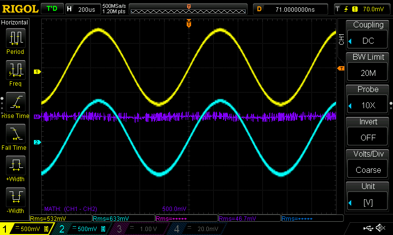
Channel 1 is the input, probed with the differential probe. Channel 2 the output with a common x10 probe.
The purple math channel is the difference between output and input. 

  • Sign in to reply

Top Comments

  • DAB
    DAB over 3 years ago +1
    Nice blog Jan. The Appnote was very interesting.
  • jc2048
    jc2048 over 3 years ago +1
    Clayton, in Linear Integrated Circuit Applications (1975), gives this for varying the gain of the single amplifier circuit. He then follows the single-amplifier circuit, in the usual way for these…
  • michaelkellett
    michaelkellett over 3 years ago in reply to jc2048 +1
    Here's yet annother, designed for single suppy 5V working to drive a high performance audio ADC. Vq from the ADC is the midrail bias voltage. MK
Parents
  • shabaz
    shabaz over 3 years ago

    Hi Jan,

    Your blog post reminds me of a technique popular with ham radio enthusiasts, who often need to convert from unbalanced to balanced (and vice-versa), but at frequencies from tens of kHz to tens or hundreds of MHz (or higher). They use 'baluns' which get built in different ways depending on the optimal frequency range and power capability. I wrote a draft blog post on them a while back, mainly a lot of theory, but never published it, It had no construction or testing of anything as such since I didn't get around to that. I don't know if it's worth still publishing, although I will not get around to writing up more on that topic for a while due to other stuff getting in the way : (

    • Cancel
    • Vote Up 0 Vote Down
    • Sign in to reply
    • More
    • Cancel
  • jc2048
    jc2048 over 3 years ago in reply to shabaz

    At 5kHz, an audio transformer should work ok as a balun. For sine waves, even repurposing a mains transformer might do.

    Here's a very old mains transformer (240V in, 12-0-12 out) - it's so old that the windings are wound on top of each other rather than on separate bobbins - and that passes a sinewave fine at 5kHz.

    image

    I'm driving it 50 ohms from a cheap function generator. The output centre tap I've offset by 1.5V relative to the 'scope ground with a battery, to show how it floats. (The red trace is the calculated difference between the two channels.)

    image

    There's about 1% difference in amplitude between the two outputs. Hardly precision stuff, but ok for experimenting, or functional testing, or fault-finding where you just want to see waveforms present.

    It doesn't do so well with other waveforms, though, because of all the inter- and intra-winding capacitance. Here's a triangle and square wave. Yuck!

    image

    image

    • Cancel
    • Vote Up 0 Vote Down
    • Sign in to reply
    • More
    • Cancel
  • jc2048
    jc2048 over 3 years ago in reply to jc2048

    Wrong! If I then add a load resistor to each output (this is with 680R), I get nicer waveforms without all the ringing.

    image

    image

    • Cancel
    • Vote Up 0 Vote Down
    • Sign in to reply
    • More
    • Cancel
  • Jan Cumps
    Jan Cumps over 3 years ago in reply to jc2048

    That's decent. I have a few higher frequency transformers here, from a design challenge and from scavenging PCBs. I'll do some tests too....

    • Cancel
    • Vote Up 0 Vote Down
    • Sign in to reply
    • More
    • Cancel
Comment
  • Jan Cumps
    Jan Cumps over 3 years ago in reply to jc2048

    That's decent. I have a few higher frequency transformers here, from a design challenge and from scavenging PCBs. I'll do some tests too....

    • Cancel
    • Vote Up 0 Vote Down
    • Sign in to reply
    • More
    • Cancel
Children
No Data
element14 Community

element14 is the first online community specifically for engineers. Connect with your peers and get expert answers to your questions.

  • Members
  • Learn
  • Technologies
  • Challenges & Projects
  • Products
  • Store
  • About Us
  • Feedback & Support
  • FAQs
  • Terms of Use
  • Privacy Policy
  • Legal and Copyright Notices
  • Sitemap
  • Cookies

An Avnet Company © 2025 Premier Farnell Limited. All Rights Reserved.

Premier Farnell Ltd, registered in England and Wales (no 00876412), registered office: Farnell House, Forge Lane, Leeds LS12 2NE.

ICP 备案号 10220084.

Follow element14

  • X
  • Facebook
  • linkedin
  • YouTube