|
A little OpAmp circuit to turn an unbalanced signal into a balanced one. |
The circuit
I took an example from tina.com: 10. Amplifiers with balanced Inputs or Outputs.
source: tina.com Amplifiers with balanced Inputs or Outputs
It's a very simple circuit, where the output of the first OpAmp is identical to the input signal - but buffered. The second OpAmp is an inverting buffer and delivers the input signal, 180° phase shifted.
Together, these two signal form a buffered rendition of the input signal, with two times the amplitude.
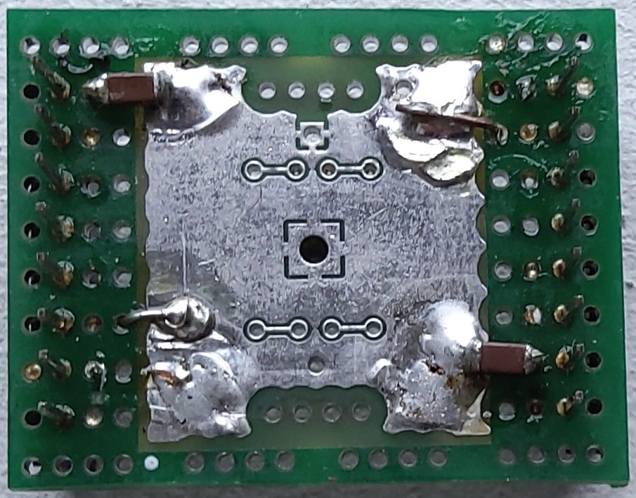
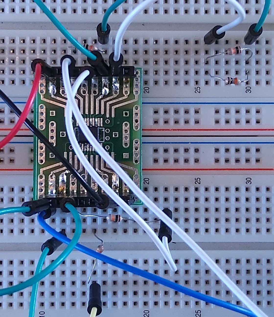
I used a TI OPA2170 dual OpAmp. It's a low power device, with decent noise specs. Bandwidth up to 1.2 MHz. On the breakout board that I made, I soldered two 1 µF decoupling capacitors.
I used 5 10K resistors. One for the input, two in parallel for the 5K resistor, and the remaining ones for the two 10K resistors of the circuit.
This design is high impedance input. The input resistor can be made much higher than the 10K I used. In my case it wasn't critical. The unbalanced input comes from a function generator. So I just took the same value as all other resistors.
I built the circuit on a breadboard. Good enough in this case, where I use a 5 KHz signal.
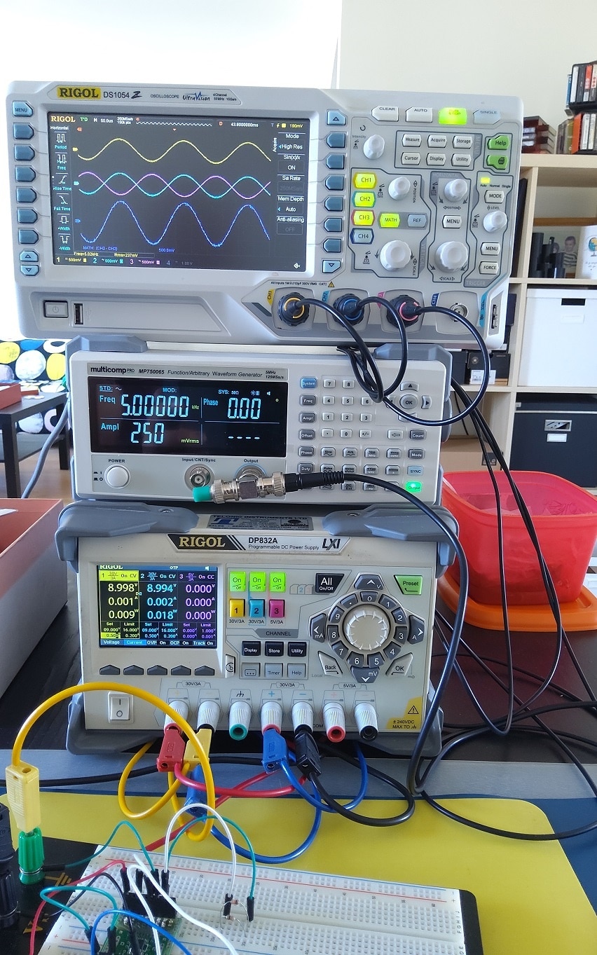
I used a balanced lab supply, set it to +9V / -9V. The function generator (the unbalanced source signal) is connected between ground and input, set to 5 KHz, 250 mVRMS, 0 V offset.
Probing a balanced signal
It's easy to probe an unbalanced signal. Connect the probe ground to ground, probe pin to the signal, and you have it.
A balanced signal runs over two wires, and none of these are ground. So you can't put your probe ground on one part, and probe pin on the other*.
A solution is to use two oscilloscope channels, and probe each of the two signals with one signal, as usual. Then use the oscilloscope's MATH function to show the difference of the two.
You see the result in the scope capture above. Channel 1 (yellow) is the unbalanced input - the signal coming out of the generator.
Channel 2 (cyan) the output of the left OpAmp. It's the bufffered input signal, and forms one part of the balanced output.
Channel 3 (magenta) is the output of the right OpAmp, and is the inverted component of the balanced output.
The difference between the two is the balanced signal. I used the Math (purple) difference (A - B: channel2 - channel 3) function to show it. Because both balanced halves have the same amplitude as the source - and are 180° inverted, the total balanced signal has double the amplitude of the input.
One of the properties of a balanced signal is that the inversion removes noise. External noise will impact both components of the balances signal almost the same. When you then take the difference, identical noise on the lines cancels itself out, while the signal keeps its form.

*you can. I leave it to fellow community members to put possibilities in the comments


-

Jan Cumps
-
Cancel
-
Vote Up
0
Vote Down
-
-
Sign in to reply
-
More
-
Cancel
-

jc2048
in reply to Jan Cumps
-
Cancel
-
Vote Up
0
Vote Down
-
-
Sign in to reply
-
More
-
Cancel
-

Jan Cumps
in reply to jc2048
-
Cancel
-
Vote Up
0
Vote Down
-
-
Sign in to reply
-
More
-
Cancel
Comment-

Jan Cumps
in reply to jc2048
-
Cancel
-
Vote Up
0
Vote Down
-
-
Sign in to reply
-
More
-
Cancel
Children