


Hi!
I'm John Marrinan, a visiting application engineer from Tektronix in the section. I work with customers right across spectrum of the measurement world and one topic that doesn’t get the attention it deserves is probing, and its effect on measurement results. Below is a short blog with some rules of thumb to remember on probing.
I think most engineers who've done design and validation of hardware will probably recognise this scenario; you setup to test, get your device under testing into the right state, it's running away, doing exactly what you want. Then you get your scope ready to see what's going on or make some measurements. You pick up your probe and start probing around at signals, then pretty quickly some goes wrong and your board stops working!! OK…….a little head scratching, a little chin rubbing and you reset the board and start again. You start probing around again the same thing happens. Quickly you come to realise that the scope and probe are causing your board to crash!!
What's going on here. Well in order for the probe to create some voltage at the scope's input it must draw some current from the circuit under test. This will fundamentally change the nature and the performance of the signal you are measuring. We generally refer to this as "loading the signal". Ideally the probe will draw as little current as possible and therefore cause as little loading as possible. Generally this is achieve by having as high impedance as possible at the probe tip. A well designed probe has tight control of the resistive, capacitive and inductive elements in order to achieve this. But like electronics probes are not perfect and have trade-offs and performance limitations. Knowing a little about probe design and its effect on signals helps users select the correct probe for the job.
For me there are three general rules to remember when looking at the effect of probes on our signals
Firstly
The probe will have its own Input Resistance. This resistance will create a voltage divider with the source resistance of the signal under test. You can see from the simple equation below that if the input resistance of the probe is much greater than the source resistance then the Vmeas will tend to equal Vsource (two resistance in parallel tend towards the lower value of the two).
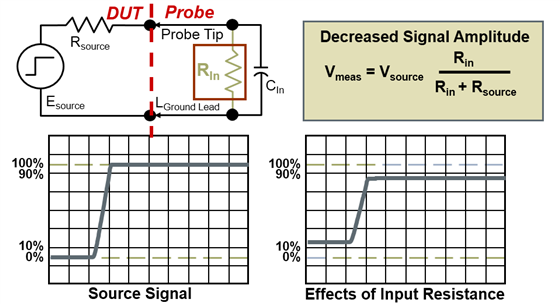
So generally a high source resistance is desirable in a probe to reduce DC loading effects by the probe and give accurate DC measurements. A 1x passive probe often have resistance in the region of 1Mohm, and many output stages are typically in the region of 10's or 100's of ohms. So a 1Mohm resistance would have every little effect on the DC levels of signals.
Secondly
As signals becomes faster and faster as switching times become shorter, by far the most important characteristics of the probe is the input capacitance. When moving away from DC and low frequencies the input impedance of a probe is dominated by the tip capacitance. The smaller the input C then the larger the probe impedance and the smaller the AC loading effect. The capacitance also has an effect on rise times. The picture below illustrates the effect a probe would have if I had an ideal 0nS step from my device. As you might remember, a capacitor fights changes in voltage. Therefore, if you drive a 0ns rise time pulse into a capacitor, it will take some amount of time for the capacitor to respond to that voltage change. The amount of time is determined by the time constant of the RC network. The figures below try to show a good estimate this effect. If the input resistance of my probe is 1Kohms and I have 100pF Cin then my rise time would be in the region of 220nS. If I can cut my Cin by an order of magnitude then the rise time scales down with it. (note for convince I've assumed that the probes resistance Rin is much larger than the source resistance Rsource.
Generally, standard passive probes have input capacitance in the region of 10-12pF, while the active probes are less than a pF.

Thirdly
The loading and capacitive effects of probes are generally out of the control of the user. The only choice they have is how much they spend on the probe. With the third element - Inductance, the user does have some control.
Longer ground leads on probes increase the inductance on the ground signal. This inductance together with the capacitance of the probe creates an LC resonance circuit and therefore ringing at a certain frequency on the step. This frequency is approximately1/√LC .

To put some figures on it 3-6inch ground leads on an active probe with an input C of around 1.5pF would give us resonance in around 350MHz - 550MHz. Ground leads add in the region of 20nH per inch. The golden rule is to keep ground leads as short as possible to minimise the inductance and to push the resonance frequency up above the bandwidth of the probe and scope. Most scope probes come with an array of tips and adaptors - I strongly recommend you investigate these and see their benefits. Here's an example of Tektronix probe grounding solutions. The first picture shows the 3inch ground clip that comes as standard with our TPP passive probes. The second option is a ground spring. So we can remove the alligator clip and replace it with a very short (0.25inch) spring wire. This has a massive effect on the lead inductance.
I have one more simple test - wiggle around the ground cable on your probe. If the signal ringing changes then chances are the probe lead inductance has an effect on the step response you see on the screen. If not then it's probably something real, and something you want to characterise!
Fig1 Alligator Clip Fig2 Ground Spring


For more information on probe loading check out this recent webinar we posted on Tek.com
Critical Considerations for Probing
Also I strongly recommend that you download the ABCs of Probes from the Tek website. It's the engineer's reference on probing basics.
Let me know your thoughts, experiences and comments on probe loading.
Thanks!
John

Top Comments
-

jmarrina
-
Cancel
-
Vote Up
+1
Vote Down
-
-
Sign in to reply
-
More
-
Cancel
Comment-

jmarrina
-
Cancel
-
Vote Up
+1
Vote Down
-
-
Sign in to reply
-
More
-
Cancel
Children