


Table of Contents
Introduction
After trying to DIY a probe setup for tiny QFN parts (see here: Probing Signals: Snooping an I2C Bus on a Tiny Surface-Mount QFN Part ), I asked if there were other options, and the community came to the rescue with a lot of ideas!
michaelkellett noticed there were quite low-cost probes available, and they looked interesting enough to give them a go!
The three-minute video shows them in use:
What’s the Problem?
When using an oscilloscope, it can be problematic to make reliable contact with traces or components on the circuit board. One option is to use solderable probes, but they can have limitations too. It would kind of be nice to have probes with some sort of adjustable mount so that the probes could poke the board standalone, leaving one’s hands free to control the oscilloscope and the entire test!
A Possible Solution
The method that the Sensepeek system employs consists of small probes attached to the end of a flexible gooseneck with a magnetic base. The general idea is that the PCB and the goosenecks are secured to a steel base magnetically, allowing adjustment. The gooseneck is very loose, and gravity, plus the locus of movements possible with a curved gooseneck controls the direction of force applied to the sprung needle point probe. For instance, if you curve the gooseneck just right, it won’t flop but will lean into the needle probe direction, which could be pressing against a component or terminal or a bare trace or pad.
The solution, therefore, requires a variety of things: the probe setup attached to a gooseneck with a magnetic base, a steel sheet, and a way of clamping the board in place.
What’s Supplied?
The Sensepeek oscilloscope probes are available in several bandwidths. At the time of purchase, the 200 MHz probes were at a discount; there were just a few £/$ difference in cost between them and the 100 MHz version, so I went with 200 MHz. The probes are model SP200 article number 4014.

Inside the bag of parts:

The probes are constructed of PCB material with a metal shield soldered on one side. The probe connection looks like an RF connector, perhaps SMC (I didn’t bother to compare it to a real SMC connector since it’s not possible to use a custom cable; you have to use the supplied probe cable, which, like most passive probes, won’t be a regular RF cable). The supplied soft probe cable incidentally is just over 70 cm long, which on paper seemed pretty short but turned out to be just right if you’re working with the ‘scope on your desk, and might even be fine if the ‘scope is at eye level, by not using the supplied cable ties. A slight negative point is that there is no 10:1 indicator pin on the 'scope BNC connector, so you'll have to manually dial in the attenuation setting on the 'scope each time you use the probes.

A spare tip is supplied, which is a good thing because those tips are tiny and might not last if accidentally pressed sideways. See the comments below for information regarding a source of spare tips.
Using the Probes
Here’s a photo of the assembled probe end. The large cylindrical metal grip has some weight to allow the springy tip to press against PCB traces with just gravity.

Incidentally, it is possible for the probe tips to push slightly sideways against a component lead, too. The gooseneck is very flexible and not stiff and can be curved into a shape to naturally push downwards and outwards slightly.
The probes need adjustment to suit the oscilloscope input. I used the oscilloscope’s built-in probe compensation feature to achieve that. I connected the shortest supplied ground wire to the probe, and then pushed in a short length of uninsulated single-core wire into the other end and touched that on the ‘scope ground, with the tip connected to the square wave output from the ‘scope, and then adjusted using the supplied trim tool. Here’s what the final adjusted output looked like; it was not perfect, but it was the best I could achieve.

The photo shows how a couple of the probes can be used to touch the connections on a QFN chip. I used this to capture I2C traffic.

I didn’t secure the PCB in any way other than relying on rubber feet. I stuck four feet on the underside of the PCB, and it had enough grip not to move.
For the base, I used a steel sheet and insulated the top surface with thin material (I used a sheet of leather which I had at hand, for a soft unnecessarily-luxury surface!
Compared to the DIY steel wires method I tried earlier, it was quicker to set up the test with the Sensepeek probes. It could be difficult (but maybe still feasible) to probe immediately adjacent connections on a QFN chip though! There is still a time and a place for DIY’ing with steel wires, and so on.
I liked that it wasn’t terribly difficult to use the Sensepeek probes. I had initially felt the system looked over-the-top with so many parts supplied, but it all assembles into something quite practical.
It is awesome that the probes can be held in place reliably and hands-free! I can see myself using these probes more frequently than I initially thought.
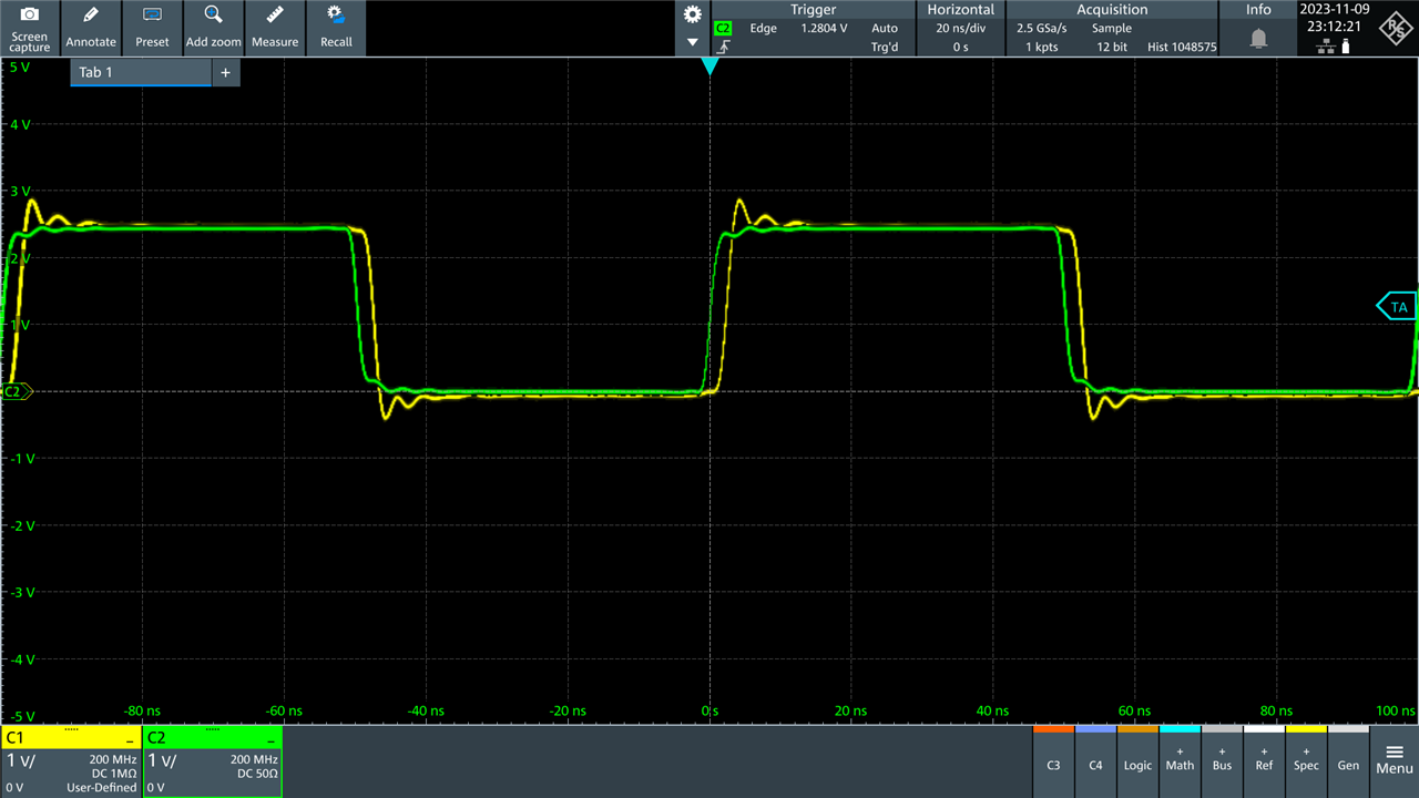
I didn’t try to perform any probe measurements, but I did connect a probe to a very sharp-edged square wave source (see here for details: Building a Fast Edge Square Wave Generator ).

First, the green trace here shows a direct coax cable connection between the square wave generator and the oscilloscope:

Next, I positioned the probe to attach to the PCB for the same signal. The yellow trace shows the probe output. The green trace has changed a bit, but that’s to be expected since the probe will create a load that affects what is seen from the coax very slightly.
Storing the Probes
I felt it would be a faff to disassemble the probes after each test session. On the other hand, if the probes are not disassembled and just thrown in the supplied plastic wallet, there is a risk of accidentally damaging the delicate tips.
I came up with the following solution. I bought a compartment storage box and removed all the dividers, leaving just the immovable one down the center. I cut a notch at one end. Finally, I took one of the dividers and trimmed it and glued it where the probe tips would be. It prevents the tips from touching the center divider. With this solution, the tips do not touch any inside surface of the box, even if the box is moved a lot or if it is placed on any side. It means I can store the probes in their fully assembled state!

The box was large enough for both probes. If you're interested, this was the specific box I used.

Summary
I was pleasantly surprised that such reasonably-cost oscilloscope probes existed that actually work quite well for hands-free tasks. The probes appear to be fairly well constructed. Obviously, the probe tip can be easily damaged, and some consideration will need to be given to how the probes will be stored. I used a modified compartment box, but you could perhaps 3D-print a probe holder; if you manage that, please share the 3D files!
Thanks for reading.
Top Comments