Table of Contents
Introduction
I had a nice "Sensirion SHT31 Smart Gadget" temperature and humidity board, which unfortunately had no connections broken out for the key component – a tiny QFN sensor that communicates using a serial I2C bus. The Sensirion board provides fast-changing and accurate ambient temperature readings. It's obsolete but there is a more recent SHT4X board . Definitely a worthwhile product. It can even log the data and provide access on a mobile phone using BLE.
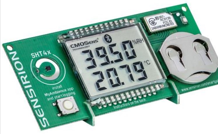
(image source: Farnell website)
I wanted to examine the I2C messages, to see if any calibration was going on, compared to the measured values shown on the LCD screen. To do that, I’d need to stick probes onto the chip : (
This blog post shows the cheap method that can be used at a pinch; there are far better tools for this, but I don’t have them! If anyone can recommend something it would be gratefully appreciated.
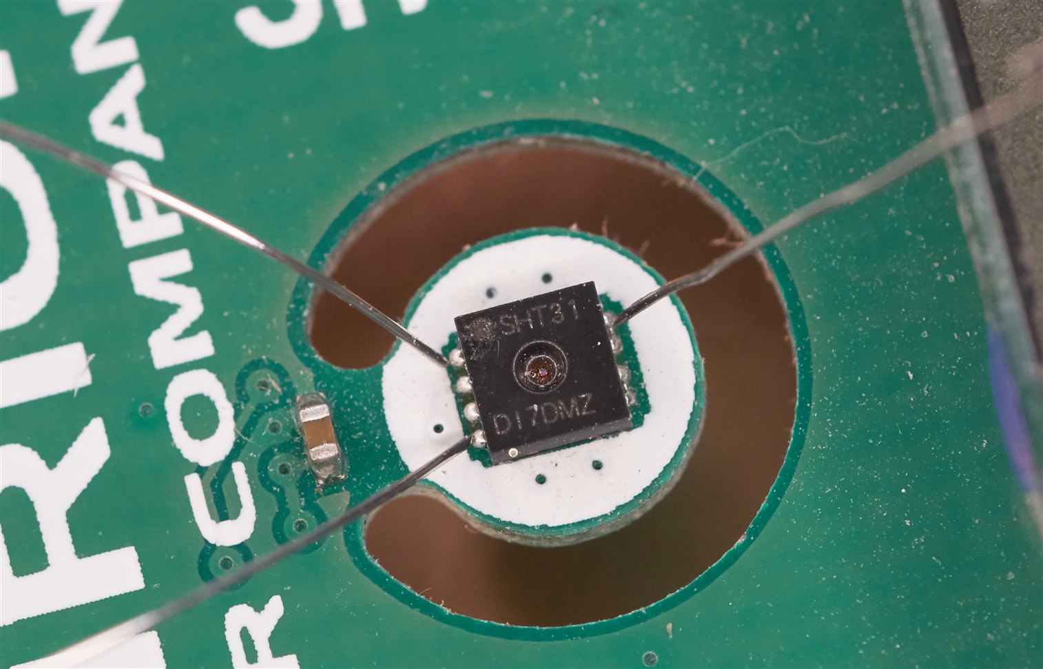
In a nutshell, I used springy steel wire and positioned them such that they were lightly digging against the QFN connections.
What’s the Problem?
Each of the QFN pads are just 0.25 mm in size, and spaced 0.5 mm apart, and a normal oscilloscope probe has no chance of making contact reliably.
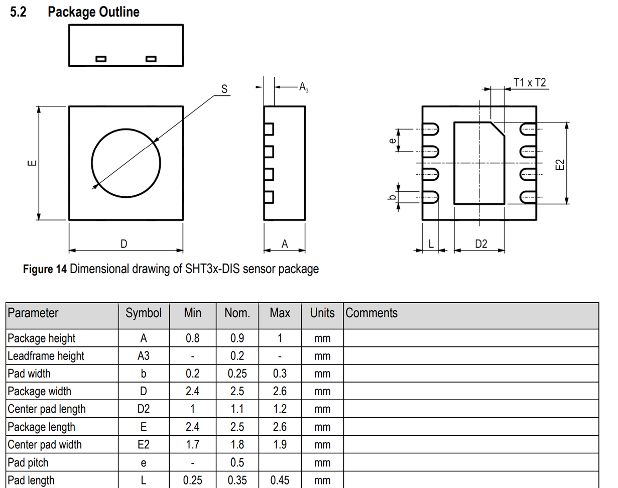
(image source: SHT31 PDF datasheet)
What’s a Solution?
I took steel wire of 0.2 mm diameter. Since it is unsolderable, I crimped a ferrule onto the end of it. A 0.5 mm ferrule was fine, I folded the steel wire once to give it enough thickness.
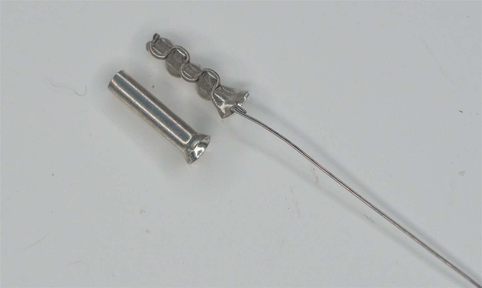
Next, I took a piece of copper-clad board, and cut out some isolated pad areas, one each for the I2C SDA and SCL connections. I soldered ‘scope probe test points, as well as the ferrules with the steel wire in them.
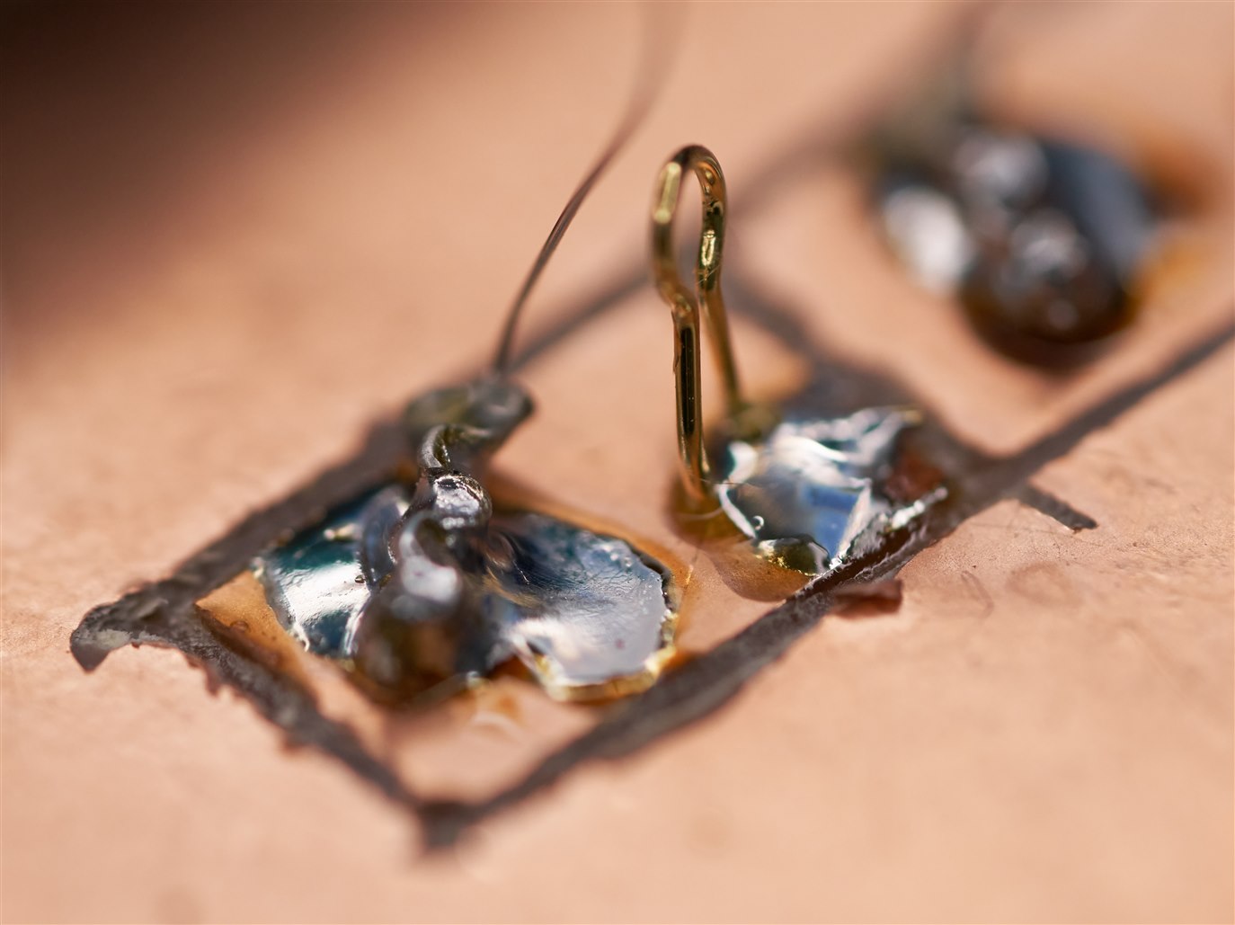
After that the board-under-test was secured in position using PolyDoh (it is easily removable) and a drop of superglue on the area between the Polydoh and the copper-clad board. This reliably holds the board without it moving at all.
Then, all that needed to be done was to position the springy steel wires, and attach the ‘scope probes!
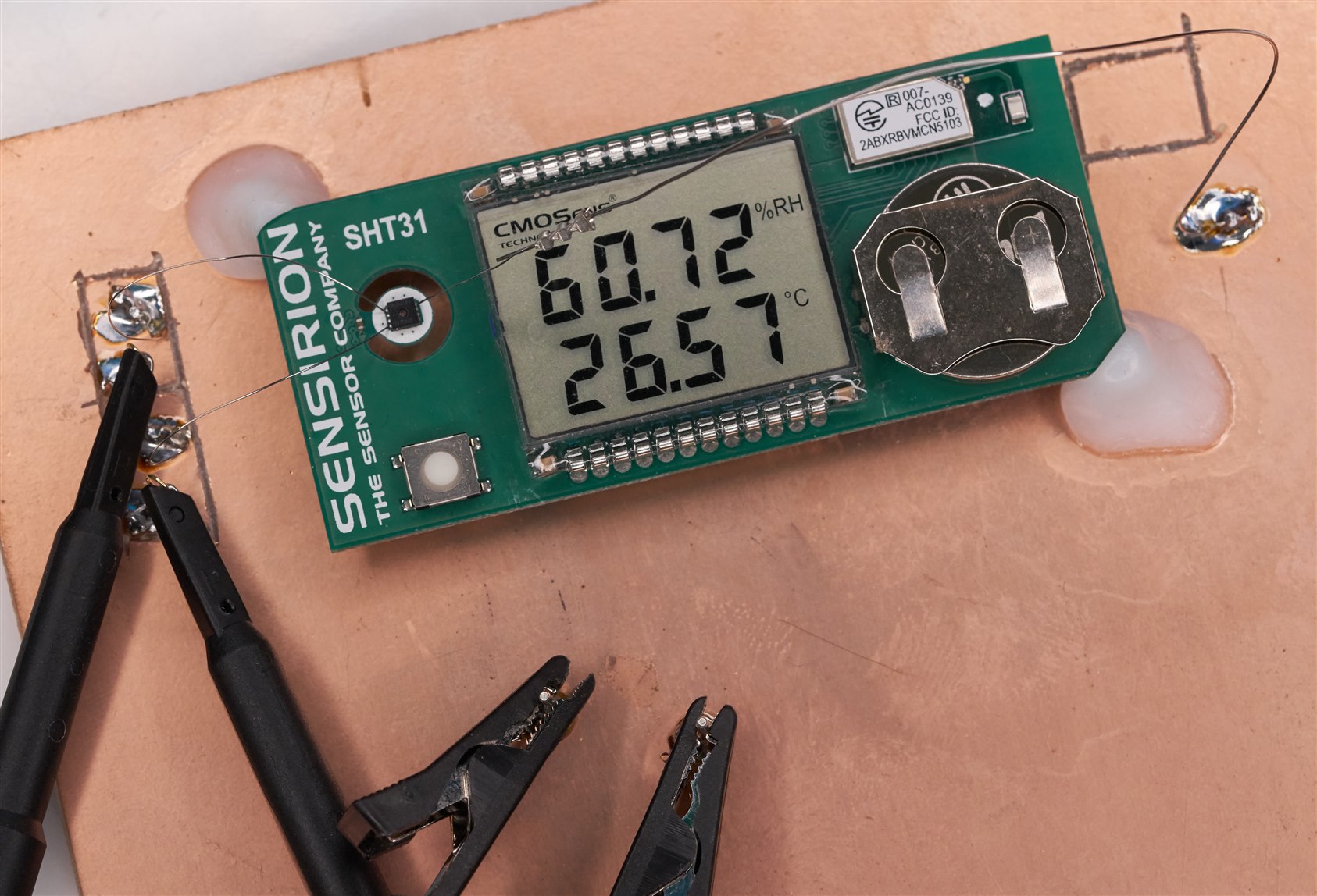
Here’s another photo showing a slightly close-up view. The connection on the right side is the 0V connection, and since it was quite long, I actually used 0.4 mm wire instead of 0.2mm, and then crimped down to 0.2 mm close to the component under test.

A birds-eye view of the wires touching the QFN connections:
And here’s the ‘scope output, decoding the I2C signal:

Summary
I suppose I should buy some actual micro probes intended for attaching to a testbed, but I don’t often need to probe QFN (if it were slightly larger I would have just tacked some Kynar wires on, or used solderable oscilloscope probes: Building Solderable In-Circuit Oscilloscope Probes ) but a hack method such as described here might be occasionally worth a shot.
If you've tried some proper tools and can recommend some, it would be great to hear about them.
Thanks for reading!
