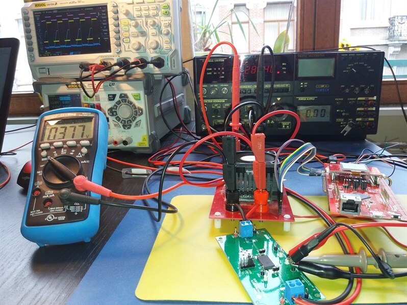
Analog Time ! I've prepared the DC Load to measure the behaviour of the circuit. In this blog series I'll show dynamic aspects of the instrument. The first blog shows the points of interest and some initial teaser measurements. If you want a particular measurement to be done, ask in the comments. |
Test Points
I've wired the main points of the control circuit - an opamp integrator:
- the inputs of the integrator (set point and measured feedback)
- the output of the integrator
- the gate of the power mossfet.
This should be enough to get a view into the dynamics of the circuit. In hindsight I could have also captured the inverting input of the integrator but I didn't.
First Setup: Square Wave input signal.
jc2048 has documented the behaviour using a simulator. One of the exercises was the reaction of the controller circuit on a square wave input.
Programmable Electronic Load: Dynamic Behaviour: Part 1 Overview
I've replicated this by passing a pulsed 0.6 V signal to the dc load and try to keep the current to 200 mA.
On the captures below, the
- yellow signal is the square wave 0.6 V 20 Hz input voltage to the dc load. It isn't a perfect square because there is output capacitance on supply.
(I don't have a square wave generator that can be loaded, so I used the TI SWIFTPower Module EVM module from the RoadTest I did a while ago and pulsed the output via the EN signal)
- purple is the TTL 20 Hz signal that I used to pulse that voltage.
- light blue is the gate voltage to of the mosfet.
- dark blue is the measured current, taken after the opamp. Inverted because the opamp has a negative gain.
The first capture shows a complete cycle:
The next one is triggered on the rising edge:
The last one is triggered on the falling edge:
That's it for this blog. It's more food for thought than actually analyzing what's happening. I think it shows enough info to start a discussion though.


Top Comments
-

jc2048
-
Cancel
-
Vote Up
+1
Vote Down
-
-
Sign in to reply
-
More
-
Cancel
-

Jan Cumps
in reply to jc2048
-
Cancel
-
Vote Up
0
Vote Down
-
-
Sign in to reply
-
More
-
Cancel
Comment-

Jan Cumps
in reply to jc2048
-
Cancel
-
Vote Up
0
Vote Down
-
-
Sign in to reply
-
More
-
Cancel
Children