element14 Community
element14 Community
    Register Log In
  • Site
  • Search
  • Log In Register
  • Community Hub
    Community Hub
    • What's New on element14
    • Feedback and Support
    • Benefits of Membership
    • Personal Blogs
    • Members Area
    • Achievement Levels
  • Learn
    Learn
    • Ask an Expert
    • eBooks
    • element14 presents
    • Learning Center
    • Tech Spotlight
    • STEM Academy
    • Webinars, Training and Events
    • Learning Groups
  • Technologies
    Technologies
    • 3D Printing
    • FPGA
    • Industrial Automation
    • Internet of Things
    • Power & Energy
    • Sensors
    • Technology Groups
  • Challenges & Projects
    Challenges & Projects
    • Design Challenges
    • element14 presents Projects
    • Project14
    • Arduino Projects
    • Raspberry Pi Projects
    • Project Groups
  • Products
    Products
    • Arduino
    • Avnet Boards Community
    • Dev Tools
    • Manufacturers
    • Multicomp Pro
    • Product Groups
    • Raspberry Pi
    • RoadTests & Reviews
  • Store
    Store
    • Visit Your Store
    • Choose another store...
      • Europe
      •  Austria (German)
      •  Belgium (Dutch, French)
      •  Bulgaria (Bulgarian)
      •  Czech Republic (Czech)
      •  Denmark (Danish)
      •  Estonia (Estonian)
      •  Finland (Finnish)
      •  France (French)
      •  Germany (German)
      •  Hungary (Hungarian)
      •  Ireland
      •  Israel
      •  Italy (Italian)
      •  Latvia (Latvian)
      •  
      •  Lithuania (Lithuanian)
      •  Netherlands (Dutch)
      •  Norway (Norwegian)
      •  Poland (Polish)
      •  Portugal (Portuguese)
      •  Romania (Romanian)
      •  Russia (Russian)
      •  Slovakia (Slovak)
      •  Slovenia (Slovenian)
      •  Spain (Spanish)
      •  Sweden (Swedish)
      •  Switzerland(German, French)
      •  Turkey (Turkish)
      •  United Kingdom
      • Asia Pacific
      •  Australia
      •  China
      •  Hong Kong
      •  India
      •  Korea (Korean)
      •  Malaysia
      •  New Zealand
      •  Philippines
      •  Singapore
      •  Taiwan
      •  Thailand (Thai)
      • Americas
      •  Brazil (Portuguese)
      •  Canada
      •  Mexico (Spanish)
      •  United States
      Can't find the country/region you're looking for? Visit our export site or find a local distributor.
  • Translate
  • Profile
  • Settings
Test & Tools
  • Technologies
  • More
Test & Tools
Blog Programmable Electronic Load - Measurements Part 1: Control Circuit
  • Blog
  • Forum
  • Documents
  • Files
  • Members
  • Mentions
  • Sub-Groups
  • Tags
  • More
  • Cancel
  • New
Join Test & Tools to participate - click to join for free!
  • Share
  • More
  • Cancel
Group Actions
  • Group RSS
  • More
  • Cancel
Engagement
  • Author Author: Jan Cumps
  • Date Created: 19 May 2018 11:29 AM Date Created
  • Views 2289 views
  • Likes 5 likes
  • Comments 6 comments
  • opamp
  • control_theory
  • feedback
  • integrator
  • dc_load
Related
Recommended

Programmable Electronic Load - Measurements Part 1: Control Circuit

Jan Cumps
Jan Cumps
19 May 2018

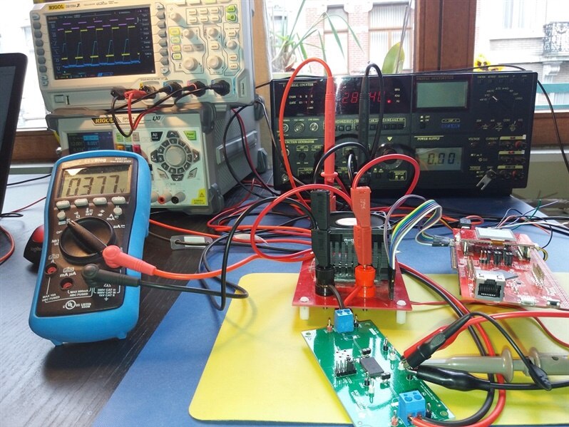
Analog Time !

I've prepared the DC Load to measure the behaviour of the circuit. In this blog series I'll show dynamic aspects of the instrument.

image

The first blog shows the points of interest and some initial teaser measurements. If you want a particular measurement to be done, ask in the comments.


Test Points


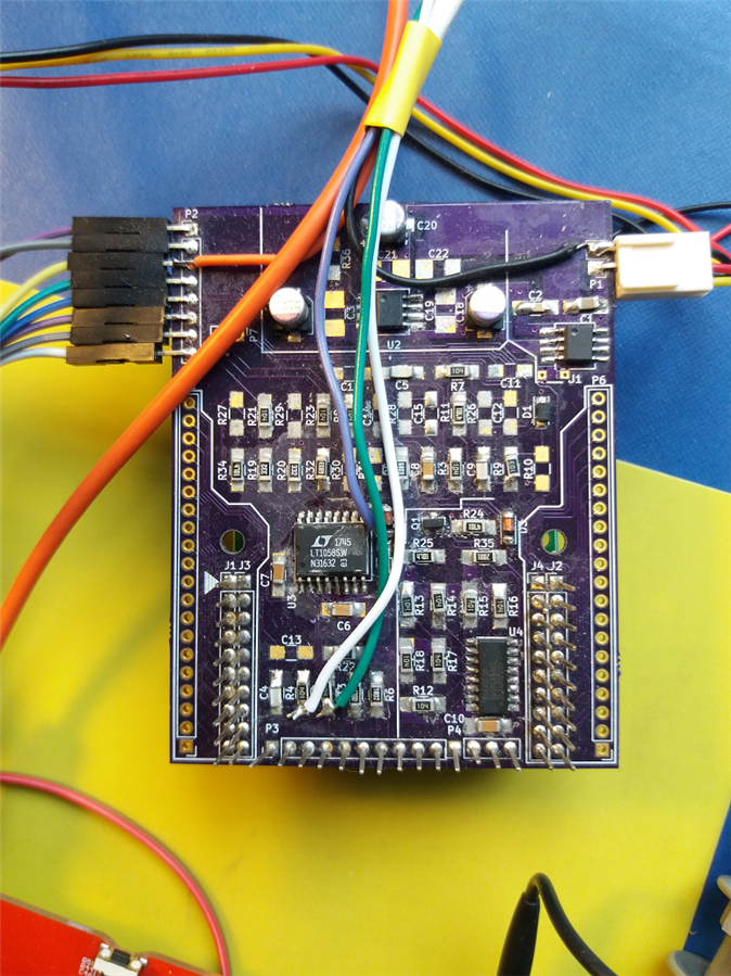
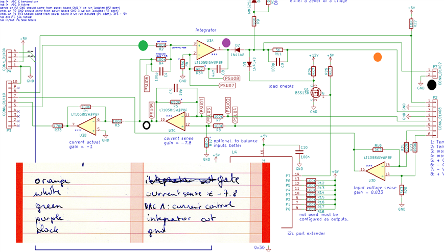
I've wired the main points of the control circuit - an opamp integrator:

  • the inputs of the integrator (set point and measured feedback)
  • the output of the integrator
  • the gate of the power mossfet.

image


This should be enough to get a view into the dynamics of the circuit. In hindsight I could have also captured the inverting input of the integrator but I didn't.


First Setup: Square Wave input signal.


jc2048 has documented the behaviour using a simulator. One of the exercises was the reaction of the controller circuit on a square wave input.

Programmable Electronic Load: Dynamic Behaviour: Part 1 Overview


I've replicated this by passing a pulsed 0.6 V signal to the dc load and try to keep the current to 200 mA.

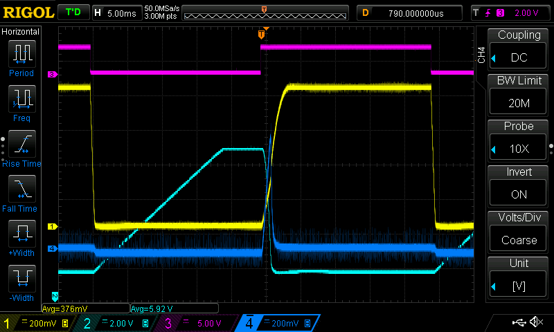
On the captures below, the

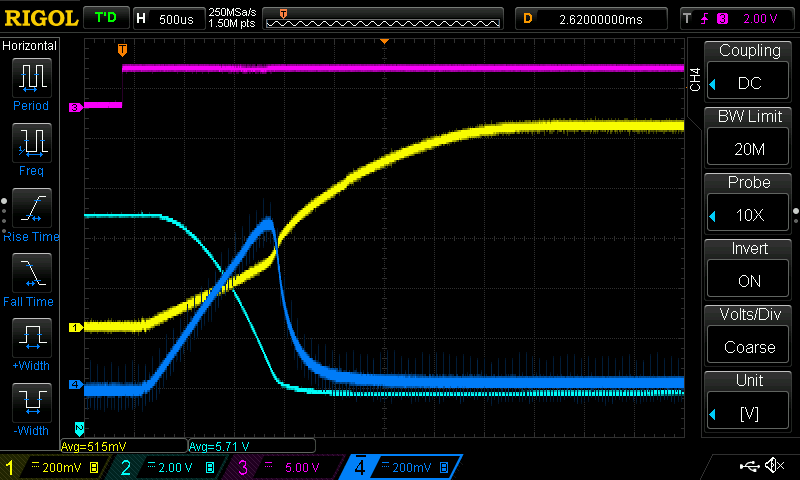
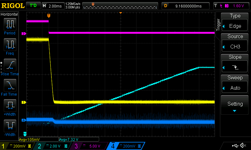
  • yellow signal is the square wave 0.6 V 20 Hz input voltage to the dc load.  It isn't a perfect square because there is output capacitance on supply.
    (I don't have a square wave generator that can be loaded, so I used the TI SWIFTTm Power Module EVM module from the RoadTest I did a while ago and pulsed the output via the EN signal)
  • purple is the TTL 20 Hz signal that I used to pulse that voltage.
  • light blue is the gate voltage to of the mosfet.
  • dark blue is the measured current, taken after the opamp. Inverted because the opamp has a negative gain.


image


The first capture shows a complete cycle:

image


The next one is triggered on the rising edge:

image


The last one is triggered on the falling edge:

image


That's it for this blog. It's more food for thought than actually analyzing what's happening. I think it shows enough info to start a discussion though.

  • Sign in to reply

Top Comments

  • jc2048
    jc2048 over 7 years ago +1
    This is confusing because there is more than one thing that can be considered as an input. That first dynamic-behaviour blog was on the effect of changing the set-point input (ie the current being demanded…
  • Jan Cumps
    Jan Cumps over 7 years ago +1
    Things you do to improve probing:
  • Jan Cumps
    Jan Cumps over 7 years ago

    Things you do to improve probing:

    image

    • Cancel
    • Vote Up +1 Vote Down
    • Sign in to reply
    • More
    • Cancel
  • Jan Cumps
    Jan Cumps over 7 years ago in reply to Jan Cumps

    This is a capture of the DAC switching from 0 to raw DAC value 10000 (represents 1.165 A)

    The difference is that here, I measured over the current sense resistor with decent probing technique.

    image

    (for the next calculations, don't look too far into the decimals. the scope isn't very precise and I've measured visually using cursors)

    With the cursors, I measured -58.80 mV over the 0.05 Ohm resistor -> 1.176 A.

    Measurement at the ADC = 398.625 mV (raw ADC value: 2125)

    That means that the gain of opamp U3C and U3B is 6,77933673469388.

    (note that the schematic gives -7.8 for U3C but that is without R32. I mounted R32 which turns the gain to - 6.8)


    edit: the yellow line was supposed to be the input voltage measured by a differential probe. I had it turned off to save battery life and forgot to turn it back on. Vin = 5 V.

    Here's the same one with the probe turned on. I left the cursors in place and glad that they still match the measuremens. You never know these days ...

    image

    • Cancel
    • Vote Up 0 Vote Down
    • Sign in to reply
    • More
    • Cancel
  • Jan Cumps
    Jan Cumps over 7 years ago in reply to jc2048

    Here are captures closer to your first post's analysis:


    A jumps from 0 A to 1.5 A


    image


    and back to 0 A:


    image


    yellow: input voltage (0.8 V)

    light blue: MOSFET gate

    purple: the DAC A output (current control)

    dark blue: current measured after opamp 3C

    • Cancel
    • Vote Up 0 Vote Down
    • Sign in to reply
    • More
    • Cancel
  • Jan Cumps
    Jan Cumps over 7 years ago in reply to jc2048

    Yes, it’s closer to this exercise: Programmable Electronic Load: Dynamic Behaviour: Part 4 Effect of Output Voltage Change . i don’t have a supply where I can provide a dc offset to the wave (I have a function generator that can do that but Its output stage is too weak to drive some interesting current).

    • Cancel
    • Vote Up 0 Vote Down
    • Sign in to reply
    • More
    • Cancel
  • jc2048
    jc2048 over 7 years ago

    This is confusing because there is more than one thing that can be considered as an input.


    That first dynamic-behaviour blog was on the effect of changing the set-point input (ie the current being demanded), so the input I was referring to was the input from the DAC.

    • Cancel
    • Vote Up +1 Vote Down
    • Sign in to reply
    • More
    • Cancel
>
element14 Community

element14 is the first online community specifically for engineers. Connect with your peers and get expert answers to your questions.

  • Members
  • Learn
  • Technologies
  • Challenges & Projects
  • Products
  • Store
  • About Us
  • Feedback & Support
  • FAQs
  • Terms of Use
  • Privacy Policy
  • Legal and Copyright Notices
  • Sitemap
  • Cookies

An Avnet Company © 2025 Premier Farnell Limited. All Rights Reserved.

Premier Farnell Ltd, registered in England and Wales (no 00876412), registered office: Farnell House, Forge Lane, Leeds LS12 2NE.

ICP 备案号 10220084.

Follow element14

  • X
  • Facebook
  • linkedin
  • YouTube