


In this post I'm going to look at the effect of inductance in the output circuit that the load is controlling.
Although you may not be specifically driving an inductor, the leads that you use have some inductance and this will have some effect on the the performance and stability. Why might the inductance have an effect? Although it's not inside the loop, the current in the circuit also passes through the sense resistor and that is inside the loop.
For this simulation I've placed an inductor in each lead and I'm going to use the parameter stepping again to vary the value so that we can get a feel for what happens. I'm going to do this for the original values and then for the values I selected for a better waveform shape and see what the difference is and whether I've unwittingly compromised the performance.
Before I do that, let's consider what a typical inductance for a lead might be. This is a formula due to Terman
L = 0.2 x length (ln(4 x length/diameter) - 0.75)
where length and diameter are in metres and the result is in uH.
For 1m of wire, with a diameter of 2mm, that gives about 1.4uH. It's important to note that the formula isn't a physical model and is very approximate - if you look at different sources you'll find different formulae. The actual inductance is the property that comes from the magnetic field that develops around the wire and that depends on the wire's physical arrangement in space and what else is close by. It also depends on frequency as at higher frequencies the current moves more towards the surface of the wire.
So we might see a few uH in each wire.
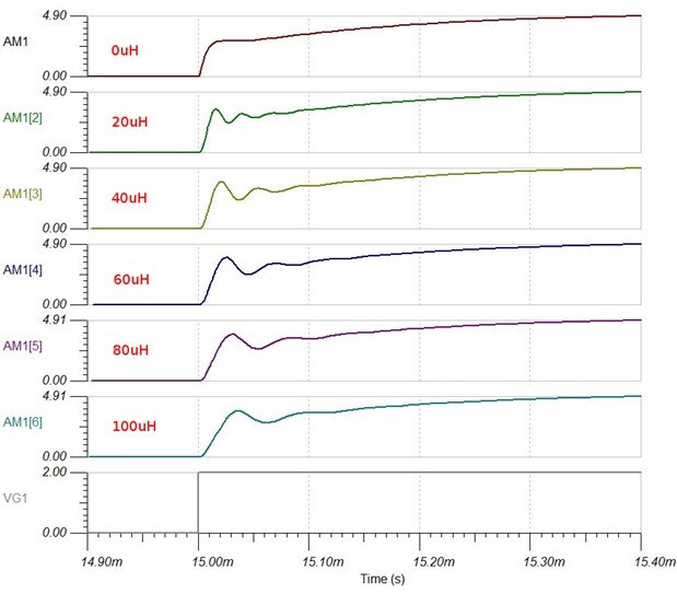
Here's the rising edge for the original circuit with C3=100pF and C2=4.7nF. I'm stepping the lead inductance by 20uH each time and I've separated the waveforms because it was too confusing having them all together. The inductance value is the inductance for each lead, so the inductance in the circuit is twice that value.
Now here's the same thing for my revised values of C3=220pF and C2=1nF
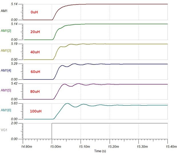
The behaviour is a bit different between the two, though less so than I expected. With higher amounts of inductance, my values ring for longer, but with lower values, close to what we'd get with actual leads it looks a bit better.
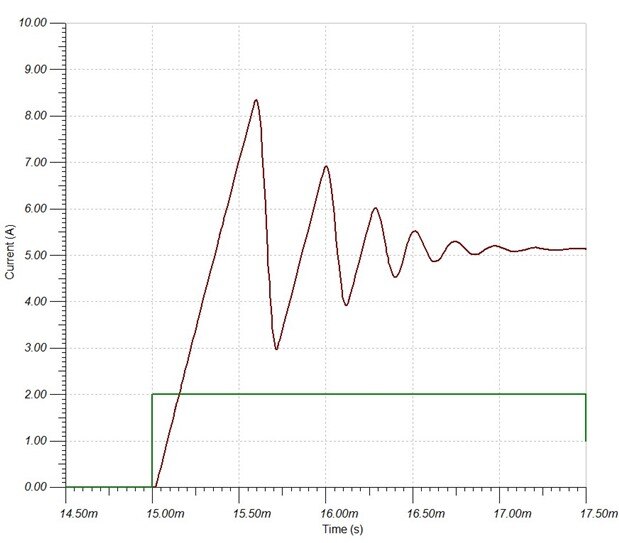
Now here's what the circuit does with 1mH in each lead. First with Peter's original values and then with mine. Here the values Peter had in his original circuit are most definitely doing better, as the overshoot is less severe and it brings things under control a lot more smoothly. This really brings us brings us back to what we are trying to achieve with this (ie what the spec is supposed to be). Is it worth compromising the waveform shape with low values of output circuit inductance to cope with much larger inductances? In reality, neither of those situations looks very comfortable to me and I think I might be looking at some kind of over-current protection to shutdown down the transistor rather than trying to make the loop handle the situation more gracefully.
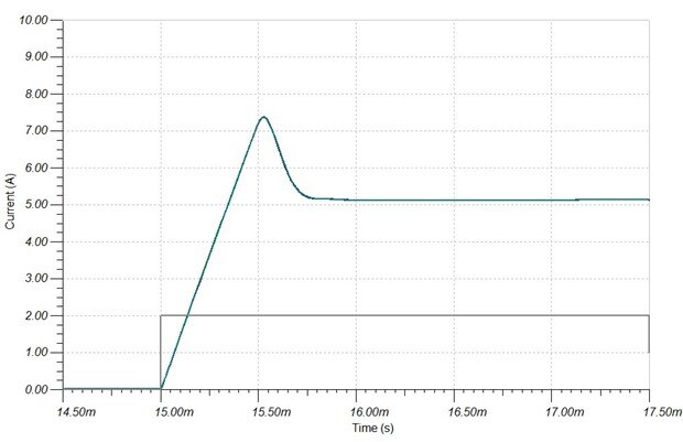
Finally here's what 1mH in each lead looks like if we ramp the input up and down rather than using a step

that's all nicely controlled because the output is keeping up with the current demanded by the control input and just meekly following it. So if we just want a precision load at DC, we can deal with high inductance simply by being careful with how fast we slew the input (assuming the voltage supplying the output load circuit isn't moving around).
Whether any of this is a problem depends very fundamentally on what the device is being used for. The inductance of the leads is fairly low anyway if they are kept short and it can be minimised further if we allow them to couple together simply by placing them next to each other where their magnetic fields then tend to cancel. If the intention is to deliberately drive actual coils, then much more work would need to be done to keep it stable and to protect the output transistor.
Something else that may be evident is that the situation with this is different to voltage/current control of a power supply. With a traditional linear power supply, there's a great big capacitor on the output and that is essentially the load of the servo system not what is hanging on the terminals. Any current control is handling the average, not the instantaneous loading. Here the servo is interacting directly with the load and the servo has to be designed and compensated accordingly.
Hope this is making a bit of sense. Not knowing the territory I'm floundering around a bit and going the long way round to get to places that some of you experts out there would go straight to.
Programmable Electronic Load: Dynamic Behaviour: Part 1 Overview
Programmable Electronic Load: Dynamic Behaviour: Part 2 The Servo Loop
Top Comments