


Table of Contents
Introduction
The Pico SCPI labTool developed by Jan Cumps allows you to connect your PC to equipment to control and monitor all sorts of things. The project grew from a series of blog posts beginning with this one: Pico SCPI Lab Switch project: automate your test setup with a standards compliant multi-channel switch
As an example, if you have relays that need to be controlled, the Pico SCPI labTool’s general-purpose input/outputs (GPIO) can be wired up to them, and then you can issue a simple text command from your PC, all under remote control (for instance, using the USB connection).

The diagram above shows how it is used – it’s very straightforward. The Pico’s USB connection is plugged into a PC, and you can run software to switch things on or off, or to chart measurements, and so on. The PC sends instructions and receives responses from the Pi Pico. The Pico is physically attached to the hardware.
The underlying instructions and responses are in a standard text format, meaning software such as LabView and MATLAB can interface it all! Python can also be used.
One advantage of this solution is that even if you’re unfamiliar with coding, that’s OK! With some of the software tools this project is compatible with, minimal actual coding can be needed to begin interacting with hardware.
I was keen to explore the project and see what it could be used for. This blog post simply discusses how to get going with it.
How Does it Work?
The solution makes use of several technologies. In particular, a text form of instructions and responses called Standard Commands for Programmable Instruments (SCPI) is used. With SCPI, if you wished to set a particular GPIO pin to a logic level high, you’d type something like:
DIGI:OUTP0 1
The first part merely indicates that a command related to digital functionality is to follow. The next part narrows it down to output #0. The final part indicates that the output should be set to logic 1 (high).
The text command is sent over USB using a standard USB Test and Measurement Class (USBTMC) method. At the Pi Pico end, the SCPI content is extracted from the message and processed by the Pico SCPI labTool code. The code then instructs the appropriate GPIO to go high.

A great benefit of using SCPI and USBTMC is that it plugs in nicely with something known as Virtual Instrument Software Architecture (VISA), at the PC end of the solution. The VISA software can connect to various hardware, including USB devices running USBTMC. The VISA Resource Manager allows access to all the hardware devices regardless of the interface type, so that the user app running on the PC doesn’t need to concern itself with direct USB or Ethernet communication and so on.
For instance, if you plug in a supported device into the network, the VISA Resource Manager will provide access to it using an identifier (known as a VISA Resource Name) such as TCPIP0::0xAABB::DMM1000::60232::INSTR whereas if you plug in the Pico SCPI labTool into your PC, the VISA Resource Name might be USB::0xCAFE::0x4000::123456::INSTR. The connecting user application doesn’t need to care whether the device is Ethernet or USB connected, although the first part of the VISA Resource Name does specify that. The rest of the string contains the manufacturer identifier (0xCAFE), model identifier (0x4000), and product serial number (123456). The final part merely specifies that instrument control resources will be accessible with that VISA Resource Name.
If you were using Python on your PC to control the digital output, it would be easy. The following lines would achieve the result of setting an output high.
import pyvisarm = pyvisa.ResourceManager()pst_instrument = rm.open_resource("USB0::0xCAFE::0x4000::123456::INSTR");level=1;pst_instrument.write(f"DIGI:OUTP0 {level}")pst_instrument.close()
If you wanted to blink a LED connected to the output, you could insert this snippet of code:
import timewhile True: pst_instrument.write(f"DIGI:OUTP0 {level}") level ^= 1 time.sleep(0.5)
Each of the .write() commands in the code above would result in the SCPI text instruction being delivered over USBTMC, through the USB connection, into the Pi Pico, where the Pico SCPI labTool (PST) software would decode it and then send the GPIO control instruction to a particular pin.
By editing the PST code, you could add new commands, such as (say) ANA:INP to obtain analog input from an ADC so that you could plot the measurements on the PC.
What is Needed?
Absolutely nothing is needed apart from a Pi Pico ! For a quick test, I soldered an LED onto pin 29 (which is GPIO 22) with the other end connect to ground through a 220 ohm resistor. That is sufficient to initially experiment with the Pico SCPI labTool, because you can issue DIGI:OUTP commands to turn the LED on and off.
Note that for future use, it would be good to get two Pico boards, because you can configure one to become a PicoProbe, which will allow you to develop software for the Pico super-fast. Alternatively, you could build a Pico-EuroCard which contains a built-in PicoProbe. In any case, all that is unessential for this blog post; as mentioned, you just need a Pi Pico.
The rest of this blog discusses how to set up the PC to build the Pico SCPI labTool firmware, and how to start using it.
Setting up the PC
The key thing that is required is the Pi Pico SDK. However, I like using an integrated development environment (IDE) called CLion, so I installed that too. CLion is free for 30 days, and after that is available at low cost to individuals (£79 + tax for a perpetual license, but there are also significant discounts – so it is worth checking if you qualify). If you don’t wish to use CLion, then Visual Code can be used. I think these two are amongst the best development environments available today; they are both extremely feature-rich. If you do try them both, I’d be interested to hear about your comparison.
To set up the PC for Pi Pico SDK and CLion development, follow the information here: Using CLion for Easier Coding with Pi Pico and C/C++
To set up the PC for Pi Pico SDK and Visual Code based development, you could follow the information at this link (I have not tried this).
Now that the PC is set up, you can work through the following tasks. All of these tasks are very quick; you can be complete in 15 minutes or less!
Note that if you don’t have a GitHub account, it is highly recommended to create one, and the tasks make use of your account. The reason is, that if you’re planning to use the PST, then you’re likely to want to make code enhancements to it over time, as you extend its capabilities. That is easiest to achieve if you have a GitHub account so that you have your own repository to make changes in, before submitting them to be merged into the original repository so that everyone can benefit from them. If you don't create a GitHub account, then you cannot do the step below containing a fork operation, and it will also mean you won't be able to follow the steps in future PST blog posts easily either, which rely on this step having occurred.
Once you have a GitHub account, proceed with the following steps! I used Windows, but all the steps will work with Linux too.

Download the scpi-parser Library
The Pico SCPI labTool requires a particular SCPI code library as a pre-requisite. You can either download the library and extract it, or you can use a Windows terminal (PowerShell) to download it automatically. It’s known as a clone operation in Git terminology.
I created a folder called C:\development\scpi and then typed the following in that folder using PowerShell:
git clone https://github.com/j123b567/scpi-parser.git

That’s it; this step is complete!
Create a replica of Pico SCPI labTool in your own GitHub Repository
Go to the Pico SCPI labTool GitHub project page, and click as shown below to fork the project! The fork action creates a replica of the entire project into your own GitHub account, so that you have your own repository of it.

Make sure you uncheck the box shown below before clicking on Create Fork.

Now a copy of the project will be visible in your GitHub account, for instance, I did the same thing: https://github.com/shabaz123/pico_scpi_usbtmc_labtool
Download the Pico SCPI labTool Project to your PC
This step creates a local copy of the files onto your PC, known as a clone operation. You could do this from the command line in a similar method as shown earlier. If you’re using CLion, then it’s easy directly from within the software. Once you start up CLion, click on Get from VCS on the main Welcome page:

From there, you can click on GitHub, and select the project from the list. Make sure the Directory box is set as you desire. In my case, I put all my Pi Pico projects into a C:\development\pico folder.

The next screen is super-important. One box needs filling in, and nothing else needs to be changed from the defaults. Type the following into the Environment box (note: it’s very important to use forward-slashes as shown, for at least the SCPI_LAB_PATH):
PICO_SDK_PATH=c:\development\pico\pico-sdk;SCPI_LIB_PATH=C:/development/scpi/scpi-parser/libscpi

Now the project will be loaded into CLion!

The yellow pop-up message in the screenshot above is OK.
Building the Code
This is a one-click task. Click on the hammer icon!
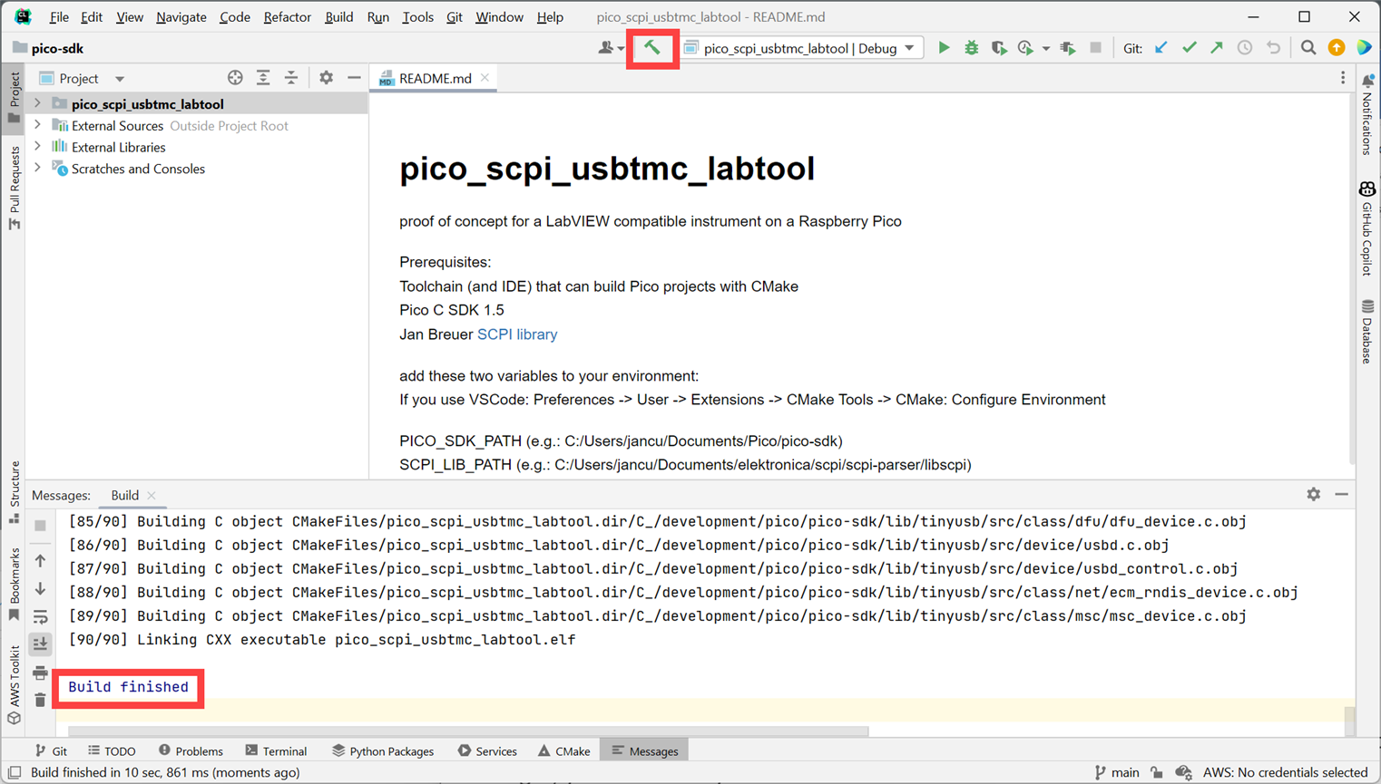
The folder shown in the screenshot below will contain the binary executable file you need:
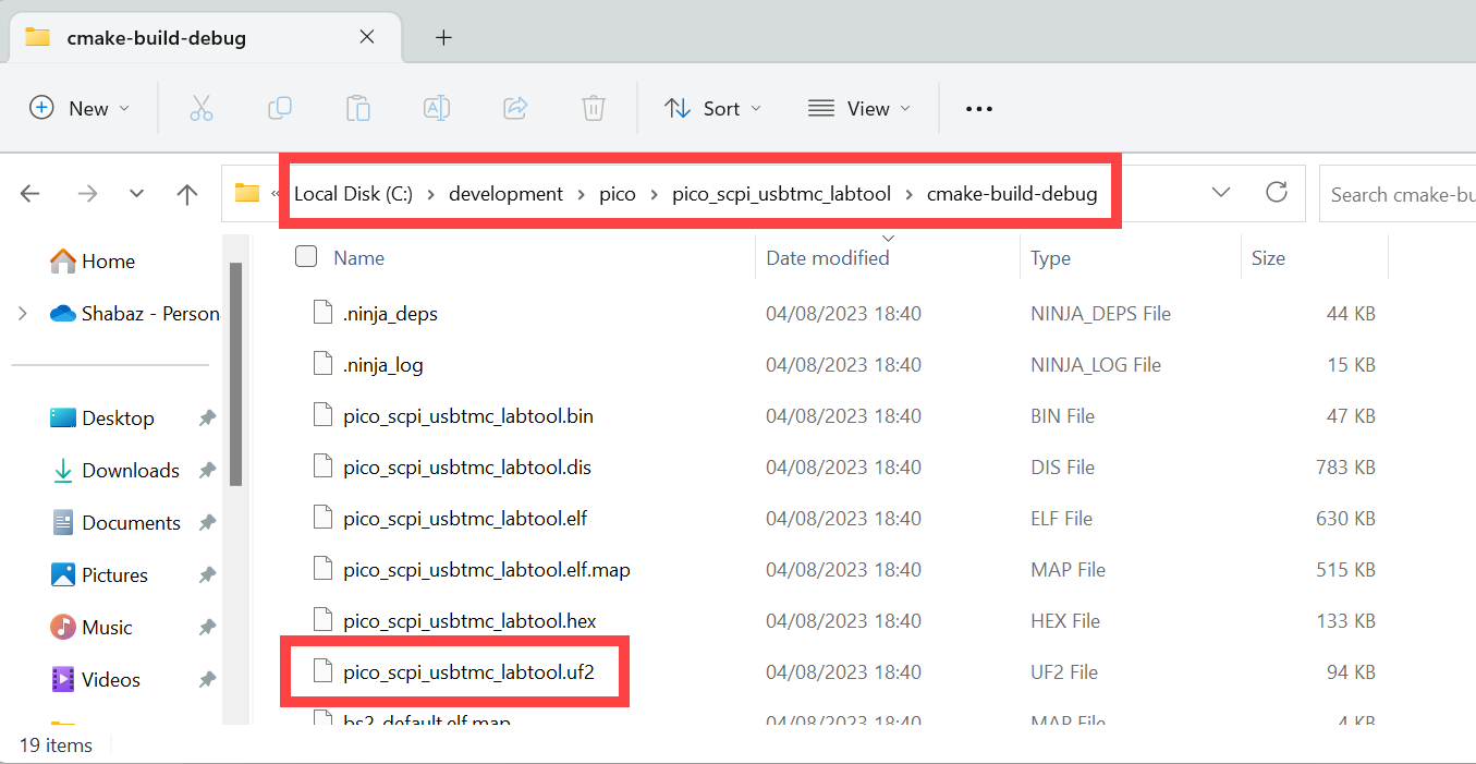
Upload the Firmware to the Pi Pico
There’s a little button on the Pi Pico (it’s the only button on it). Holding it down, plug the Pico’s USB connector into the PC. Wait a couple of seconds, and then release the button.
A file explorer window will appear, i.e. the Pi Pico will look like a storage drive to the PC. You can drag-and-drop the .uf2 file into this window. Within seconds, the firmware will be installed.
Using It
The Pico SCPI labTool (PST) is quick. I plugged the USB connector from the Pi Pico into the PC, and it was detected by the driver software before I’d even let go of the plug!

I happened to have Tektronix software installed, which includes VISA code, and it can access instruments. I clicked on the software and it allowed me to type SCPI instructions, and see the results!

Of course, Tektronix software is not necessary. You could install VISA directly from the National Instruments website.
Now you’re ready to try it out!
If you installed the NI software, then use a supplied tool called VISA Interactive Control, and select the PST as shown here, and double-click it:

A new window will open. Click on Input/Output and then type the following (it may be present as the default on startup anyway, in which case you don't need to type it!) and then press the button labeled Query:
*IDN?\n
You should see a response containing the text PICO-PI,LABTOOL.

Note: The NI Visa Interactive Control will require the user to type \n on the end of each command, whereas some tools such as the Tektronix one doesn't require that.
Now try typing DIGI:OUTP0 1 (followed by \n if you're using the NI Visa Interactive Control) and press the button labeled Write. If you have an LED soldered to GPIO 22 (pin 29) on the Pi Pico, it should light up!
If you have Python installed on the PC, then try out these example lines of code, which are the same as that shown in the introduction:
import pyvisarm = pyvisa.ResourceManager()pst_instrument = rm.open_resource("USB0::0xCAFE::0x4000::123456::INSTR");level=1;pst_instrument.write(f"DIGI:OUTP0 {level}")pst_instrument.close()
If you're using Matlab, then the following example code may be helpful. Note that this is using syntax that is backward compatible with older releases, but is deprecated; the visa object is replaced with visadev, and the older commands may be removed in future Matlab releases, although it works today.
pst1_resourcename = 'USB0::0xCAFE::0x4000::E66118604B727B22::0::INSTR';pst1 = instrfind('Type', 'visa-usb', 'RsrcName', pst1_resourcename, 'Tag', '');if isempty(pst1) % Create if it didn't exist pst1 = visa('NI', pst1_resourcename);else fclose(pst1); pst1 = pst1(1);endfopen(pst1);set(pst1, 'EOSCharCode', 'LF'); % use 0x0a aka \n aka line feed set(pst1, 'EOSMode', 'read&write'); % use that code for read and write!% ok send some stuffidentity = query(pst1, '*IDN?'); % do a *IDN? queryfprintf(pst1, 'DIGI:OUTP0 1'); % set output #0 (GPIO22) highinput_level = str2num(query(pst1, 'DIGI:INP2?')); % get input #2 (GPIO27) value
Next Steps
Now that the Pico SCPI labTool is installed on the Pi Pico, and you know how to build the code, modifying it to add new features should be possible. On the PC side, you may wish to install NI LabVIEW or MATLAB, or you may wish to continue with Python. There are many other options, too; it would be great to hear about how people use the PST project.
Summary
The Pico SCPI labTool has enormous potential. It is easy to install and use, and the fact that it runs standard protocols means it can be directly interfaced with Python, LabVIEW, and MATLAB. Multiple PST devices could be controlled, in conjunction with off-the-shelf lab instruments such as oscilloscopes and bench multimeters, to build automated solutions or to capture or control devices that would ordinarily not interface to a PC easily. The PST is ultra-low-cost yet is extremely powerful.
As mentioned earlier, it will be interesting to see how people use it.
Thanks for reading!
Top Comments