


Unfortunately my trusty old Rigol DS1052e oscilloscope suffered from damage on the way to the calibration laboratory.
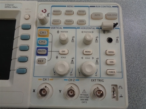
The control knob for the trigger level had been broken off and the calibration lab advised that they could not repair the device, so I asked for it to be sent back to me to see what I could do with it.
A search of the internet revealed some information on the encoders utilised within the scope as there had been a few posts on forums of failures of the encoders.
Getting hold of the right encoder however has been a little troublesome. Details I found, identified them as an Alps EC12 series encoder, with 12 pulses per revolution, no detent, a single pole switch underneath and a 15mm long flatted shaft.
Searching the common electronic component suppliers within the UK did not produce the right encoder. There were several Alps encoders to be found that were either 12 pulses without the switch or 18 and 24 pulses with the switch. I eventually found a Bourns encoder that offered the right number of pulses along with the switch and mechanical size constraints, but these were not going to be in stock until December.
As I need the oscilloscope for some work testing generator rotors in October, I decided to opt for a 12 pulse encoder but with detents and without the switch, available from Farnell, part number 206-5051, as an interim measure to get the scope back up and running. The switch element just allows the trigger level to be zeroed quickly, which in all honesty, I can't actually ever remember having used.
The scope was dismantled relatively easily. The on/off switch cap has to be pulled upwards to remove it, a small piece of card wrapped around it allows a pair of pliers to be utilised to pull it upwards. There are then four torx head screws that hold the back cover in place. Two at the bottom are easily found, but there are also two screws at the top hidden by the handle, that needs to be positioned correctly to allow access to them.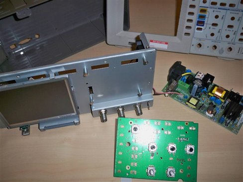
With the switch and screws removed, the rear case can be removed. The case has to be prised over the two screws that hold the mains socket in place. These cannot be removed before taking the rear case off as they are actually a nut and bolt assembly, through the inner chassis.
With the rear case off, the screw adapters either side of the D-socket are removed to allow the rear shield to be removed. This just pulls straight off as there is nothing else other than location tabs to hold it in place. The top shield can then be removed by unscrewing the top two torx screws holding it in place.
One of the screws holding the front cover in place is located behind the power supply board and so the supply board must also be removed. The connector to the main board is unplugged, and a torx screw secures an earth connection to the shield. With this removed, the two nuts and bolts securing the mains socket to the shield are undone. This then just leaves four screws holding the pub to the shield. With these removed, the power supply board can be move forward to gain access to a three pin plug at the rear of the board. After removing the power supply, all of the control knobs are removed and then the front cover can be removed to gain access to the control board containing the encoders. There are only five acres that hold the front cover in place and these are easily found with the supply board removed.
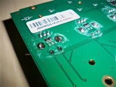
The control board itself needs to be disconnected from the main board and then the four screws securing it are removed. The whole board can then be removed while feeding the connecting ribbon cable through the slot in the inner case.
Inspection of the board revealed that some manual soldering has probably already been undertaken during assembly, seen as white deposits around the original solder connections. The damaged encoder was desoldered and removed from the board and the new one soldered in its place. 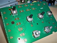
The oscilloscope was then part assembled, with the control board, front cover and power supply board all refitted, to allow the oscilloscope to be powered up and the operation of the new encoder tested. Remember to reconnect the small plug behind the power supply board and the earth lead to the chassis.
With the new encoder for the trigger level functioning well, the rest of the oscilloscope could be reassembled. Now all I need to do is get the oscilloscope off to the calibration laboratory and it will be fit for use again.
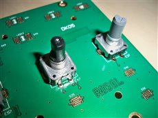
With the oscilloscope rebuilt, I couldn't resist dismantling the encoder. Four little tabs need to be prised upwards and then all of the switch and the rotary encoder can be taken out of the metal frame.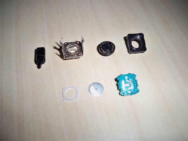
The plastic shaft has been snapped and there does appear to be some bits missing from it as there is no extension left to go through the encoder mechanism and push down onto the switch. The switch itself, just consists of the two contacts formed into the plastic case with a metallic disc installed over the top to act as both the switch to short the contacts and the spring loaded mechanism when the plastic shaft is released.
A more detailed examination of the encoder showed that there was actually eight contacts for each of the two outside pins of the encoder. This definitely isn't a 12 pulse per revolution encoder, which probably explains why I struggled so much to find one to replace it with.
Eight contacts to me suggests a 24 pulses per revolution encoder and this was confirmed by reassembling the encoder mechanism and testing. As I don't have any digital testingcapability other than a home built logic probe from back in the days when I was an apprentice, it boiled down to testing the encoder with an ohmmeter, which took a few of revolutions to confirm that it was indeed a 24 pulse per revolution encoder.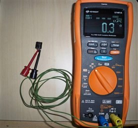
A quick scan through the Farnell website and I found a Bourns compatible encoder, part number 266-3518, to match the original Alps encoder, with the added bonus of them being in stock.
Might have been a better idea to have stripped the oscilloscope first and removed the encoders to identify what they were. Ah well, I will probably strip down the oscilloscope again after I have completed the testing required, and replace all of the encoders, as the other ones were showing signs of wear.
Top Comments