


Table of Contents
Introduction
Since time immemorial, the continuity tester has always been just a dial setting on multimeters. That’s adequate most of the time, but it can be irritating depending on how the feature has been implemented.
With some multimeters, quite a high voltage is generated on the probes during the continuity test. Other multimeters may auto-power-off halfway through testing, and you may never notice until you realize that the instrument is no longer beeping when continuity is expected. Yet another issue is that the threshold for detecting continuity is quite high; some tens of ohms of resistance may still cause the meter to beep. This project aims to solve these issues! The end result is a very compact and low-cost 2 x AAA cell powered continuity tester.

How Does it Work?
I cannot take credit for the circuit; it was on the Internet, reverse-engineered from a commercial product (no longer available called the SF10 Short Finder). I decided to use that circuit with just a few minor tweaks. Special thanks to Jan Cumps and genebren, who helped me figure out how the circuit worked (see the comments here: Brush and Large-Area Multi-Meter Probes for PCB Reverse-Engineering: A DIY Approach! ); also, see Jan’s blog post about a comparator circuit that is used in this project: OpAmp as Schmitt-trigger

The circuit works by generating a current-limited, low voltage (0.5V) using op-amp U1A, across the probes. The voltage across the probes is amplified with the inverting amplifier U1B, and then passed to a comparator circuit (U1C) with hysteresis. The hysteresis is used to reduce crackle caused by varying contact pressure on the probes, causing a slight change in resistance. The output from the comparator is inverted using op-amp U1D, and then fed into a 555 monostable circuit (U2). The purpose of the monostable is to slightly stretch the output, so that even if continuity is detected only briefly, it will still be identifiable. Finally, the signal reaches the 555 astable multivibrator U3, which is brought out of reset to generate a tone through a speaker.
The gain of the amplifier U1B is adjustable using a trimmer resistor; by adjusting this, you can set the amount of acceptable contact resistance to determine continuity. The original SF10 product could be adjusted down to 10 ohm resistance, apparently. The values in the circuit above are tweaked slightly, so that the minimum resistance can be reduced further, because 10 ohm seemed too high.
Building It
The PCB Gerber zip file is available at the Easy Continuity Tester GitHub repository. Any PCB manufacturer should be able to accept it. The design uses quite large surface-mount parts (0805-sized passives and SOIC-sized integrated circuits), so it’s easy to construct.

The photo below shows everything complete (apart from the banana socket wiring) prior to fitting into the enclosure. For the speaker, I used part code 41.T70P015H-LF. The toggle switch is part code T8019L (available from AliExpress).

The circuit is easy to construct, but it’s a tight squeeze in the enclosure (Hammond 1591XXMGY), caused by the 4mm banana sockets. If you don’t need the sockets (for instance, if you intend to permanently wire a couple of test leads to the circuit) then everything will fit in the enclosure with plenty of space to spare. There’s an even smaller enclosure (Multicomp G404) that can be used in that case.

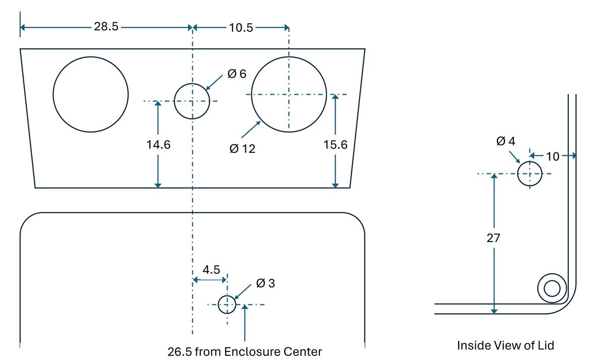
If you're using the Hammond enclosure, the drilling detail is here:
Setting Up and Using It
I decided to use 2 x AAA alkaline cells; I have not tested with rechargeable batteries. Results may vary slightly depending on the battery voltage.
With the trimmer resistor set fully clockwise, the resistance needed to cause the continuity beep to sound, is approximately 3 ohm. There’s some hysteresis, so the sound will continue until the resistance increases to 3.3 ohm. There may well be a few tens of milliohms (or maybe even a few hundred milliohms) of varying contact resistance, and the hysteresis within the circuit will tolerate that and continue to sound the beep.
With the trimmer fully anti-clockwise, the trigger resistance is about 18 ohms. For my purposes, I set the trimmer fully clockwise.
Using the continuity tester is self-explanatory! It appears to work as expected. The responsiveness is great; it beats using the continuity feature on some of the multimeters that I tried.
Current consumption is about 4 mA, increasing to 45 mA when beeping. The beeping sound is about the same tone and volume as any typical multimeter. The beeping current consumption could be reduced with a slightly better output circuit (perhaps even just using a capacitor on the output), but I didn’t investigate that; it’s an exercise for another day. Meanwhile, the circuit works, and it’s time to use it!
Summary
It’s frustrating to use the continuity feature in some multimeters, so it can make sense to have a simple, dedicated little instrument for this purpose. The circuit described here is easy to construct, and solves some of the problems seen in multimeter-based continuity testers.
Thanks for reading!

image source: Google images

