element14 Community
element14 Community
    Register Log In
  • Site
  • Search
  • Log In Register
  • Community Hub
    Community Hub
    • What's New on element14
    • Feedback and Support
    • Benefits of Membership
    • Personal Blogs
    • Members Area
    • Achievement Levels
  • Learn
    Learn
    • Ask an Expert
    • eBooks
    • element14 presents
    • Learning Center
    • Tech Spotlight
    • STEM Academy
    • Webinars, Training and Events
    • Learning Groups
  • Technologies
    Technologies
    • 3D Printing
    • FPGA
    • Industrial Automation
    • Internet of Things
    • Power & Energy
    • Sensors
    • Technology Groups
  • Challenges & Projects
    Challenges & Projects
    • Design Challenges
    • element14 presents Projects
    • Project14
    • Arduino Projects
    • Raspberry Pi Projects
    • Project Groups
  • Products
    Products
    • Arduino
    • Avnet & Tria Boards Community
    • Dev Tools
    • Manufacturers
    • Multicomp Pro
    • Product Groups
    • Raspberry Pi
    • RoadTests & Reviews
  • About Us
    About the element14 Community
  • Store
    Store
    • Visit Your Store
    • Choose another store...
      • Europe
      •  Austria (German)
      •  Belgium (Dutch, French)
      •  Bulgaria (Bulgarian)
      •  Czech Republic (Czech)
      •  Denmark (Danish)
      •  Estonia (Estonian)
      •  Finland (Finnish)
      •  France (French)
      •  Germany (German)
      •  Hungary (Hungarian)
      •  Ireland
      •  Israel
      •  Italy (Italian)
      •  Latvia (Latvian)
      •  
      •  Lithuania (Lithuanian)
      •  Netherlands (Dutch)
      •  Norway (Norwegian)
      •  Poland (Polish)
      •  Portugal (Portuguese)
      •  Romania (Romanian)
      •  Russia (Russian)
      •  Slovakia (Slovak)
      •  Slovenia (Slovenian)
      •  Spain (Spanish)
      •  Sweden (Swedish)
      •  Switzerland(German, French)
      •  Turkey (Turkish)
      •  United Kingdom
      • Asia Pacific
      •  Australia
      •  China
      •  Hong Kong
      •  India
      •  Japan
      •  Korea (Korean)
      •  Malaysia
      •  New Zealand
      •  Philippines
      •  Singapore
      •  Taiwan
      •  Thailand (Thai)
      •  Vietnam
      • Americas
      •  Brazil (Portuguese)
      •  Canada
      •  Mexico (Spanish)
      •  United States
      Can't find the country/region you're looking for? Visit our export site or find a local distributor.
  • Translate
  • Profile
  • Settings
Test & Tools
  • Technologies
  • More
Test & Tools
Blog The Modular Bench Power Supply ++, Putting it all together, the bare bones
  • Blog
  • Forum
  • Documents
  • Files
  • Members
  • Mentions
  • Sub-Groups
  • Tags
  • More
  • Cancel
  • New
Join Test & Tools to participate - click to join for free!
  • Share
  • More
  • Cancel
Group Actions
  • Group RSS
  • More
  • Cancel
Engagement
  • Author Author: Robert Peter Oakes
  • Date Created: 4 Dec 2014 5:45 AM Date Created
  • Views 4194 views
  • Likes 3 likes
  • Comments 16 comments
  • bench
  • tutorials
  • modular
  • supply
  • power
Related
Recommended

The Modular Bench Power Supply ++, Putting it all together, the bare bones

Robert Peter Oakes
Robert Peter Oakes
4 Dec 2014

I will be putting together the video this week end to go with this schematic but I thought i would share this with you in the mean time

VCC can be as much as 40V (I was powering the test circuit on a breadboard with a bench PSU for now set to 30V, my psu max)

image

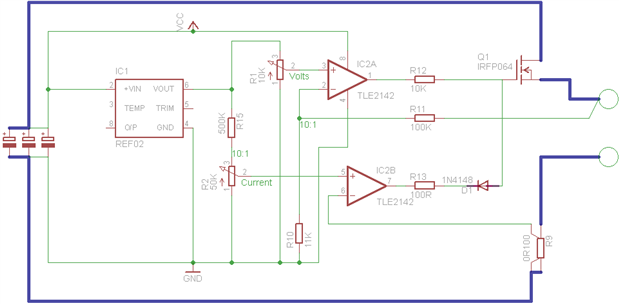
In the video I will be reviewing the behaviour of this circuit as well as Identifying a few pitfalls (Nothing serious and probably acceptable for a basic PSU but we do want to evaluate where we can improve on things

If you think you know the potential issues, please post and we will compare notes at the weekend image (There are two primary ones)


Here is the video that describes and goes through some basic tests of this circuit

You don't have permission to edit metadata of this video.
Edit media
x
image
Upload Preview
image

Enjoy, again, a little detailed so its is about an hour long


I will be adding notes etc in the next few days

  • Sign in to reply
Parents
  • jw0752
    jw0752 over 11 years ago

    Hi Peter, I have studied your schematic. If I am interpreting it correctly you have a voltage regulated power supply with an adjustable max 10 A current limiter. I did not realize before that Op Amps could sink current as well as supply it but the orientation of the D1 leads me to believe that IC2B will limit the voltage of the HEX FET if the current climbs higher than your limit set by R2. The one short coming that I can see is that you have control rails tied to the power rails without regulation. You mentioned earlier that you might work the control power at a lower voltage. If there are other things I do not see them and will be anxious to learn.

    John

    • Cancel
    • Vote Up 0 Vote Down
    • Sign in to reply
    • More
    • Cancel
  • Robert Peter Oakes
    Robert Peter Oakes over 11 years ago in reply to jw0752

    Basic theory is correct, diode prevents the current limiter from pushing up the Gate voltage when not in limit mode


    range is 5A, not 10A (100mOhm resistor, a 10:1 divider from a REF02 5V reference chip) based on 100mOhm resistor and a 0-500mV ref range on the current side


    The voltage control can technically go to 50V (Based on 5V reference and 10:1 divider network) but of course the supply is only 30 so it will cap out somewhere less than 30V... but where image?


    Current limiting is based on the kelvin resistor at the bottom right of the diagram measuring between 0 and top of the resistor, is there an issue here image?


    Can current limiting take the output down to 0mA (0V) like the voltage control can image?


    Yes Op amps can sink as well as source, comparators often only sink but that's not what we are using,


    Not using a regulator as I'm currently using a 30V bench supply and the components can all handle in excess of 40V, even if the supply changes, the stable Vref will keep things on an even keel so this is not an issue (Within reason of course)


    I dropped some hits image

    • Cancel
    • Vote Up 0 Vote Down
    • Sign in to reply
    • More
    • Cancel
Comment
  • Robert Peter Oakes
    Robert Peter Oakes over 11 years ago in reply to jw0752

    Basic theory is correct, diode prevents the current limiter from pushing up the Gate voltage when not in limit mode


    range is 5A, not 10A (100mOhm resistor, a 10:1 divider from a REF02 5V reference chip) based on 100mOhm resistor and a 0-500mV ref range on the current side


    The voltage control can technically go to 50V (Based on 5V reference and 10:1 divider network) but of course the supply is only 30 so it will cap out somewhere less than 30V... but where image?


    Current limiting is based on the kelvin resistor at the bottom right of the diagram measuring between 0 and top of the resistor, is there an issue here image?


    Can current limiting take the output down to 0mA (0V) like the voltage control can image?


    Yes Op amps can sink as well as source, comparators often only sink but that's not what we are using,


    Not using a regulator as I'm currently using a 30V bench supply and the components can all handle in excess of 40V, even if the supply changes, the stable Vref will keep things on an even keel so this is not an issue (Within reason of course)


    I dropped some hits image

    • Cancel
    • Vote Up 0 Vote Down
    • Sign in to reply
    • More
    • Cancel
Children
  • Robert Peter Oakes
    Robert Peter Oakes over 11 years ago in reply to Robert Peter Oakes

    Anyone want to give the answers a go... come on, give it a go image, John will beat you to the punch if your too slow

    • Cancel
    • Vote Up 0 Vote Down
    • Sign in to reply
    • More
    • Cancel
  • jw0752
    jw0752 over 11 years ago in reply to Robert Peter Oakes

    I am embarrassed that I missed the 5 A limit last night in my calculations. Of course our reference is 5 volts and you have a 10 : 1 voltage divider which gives us a max 0.5 volts on the non-inverting input to the Op Amp. The voltage drop across the 0R100 resistor is 0.5 volts when the current is 5 Amps which ties to the inverting input to the Op Amp and will shut it down at that current level and cause it to begin to sink current away from the gate of the HexFet. Since I am on this line of reasoning I will say that the current limiter will not be able to pull the voltage output all the way to the 0 volt rail because the voltage drop across the D1 will be at a minimum 0.7 volts. We might be able to improve this if we change to a schottky diode with a 0.4 volt junction drop. There will also be the drop across the 100R resistor R-13 which will limit the current regulator's ability to pull sink the gate of the Hex Fet all the way down. Hopefully I am not too far off in my analysis this time. Let me know though, I usually make more mistakes than I do corrects. I will think for a while on the other question and get back to you.

    John

    • Cancel
    • Vote Up 0 Vote Down
    • Sign in to reply
    • More
    • Cancel
  • Robert Peter Oakes
    Robert Peter Oakes over 11 years ago in reply to jw0752

    Very good so far, and nothing to be embarrassed about, we all make a woopsie on occasion, goes with the maturity we have image


    Now the current through the 100R resistor will be almost negligible as  it ill be limited by the 100K to the output of the voltage op amp, nothing from the FET unless you start measuring femto amps or less through the leakage of the fet gate, but I think we can ignore that.


    As the current regulator pulls the volts away from the FET gate, the voltage op amp will of course try to correct for that and turn up its output to the max , so the current through the 100K and 100R will be (30V-0.7)/100100 which of course is 293uA resulting in only 29mV across the 100R resistor, as I said negligible (Maybe a little less as the op amp output volts will never truly get to the supply either so theoretically this should be low enough to turn off the FET (2V min Vgs Threshold), now with that low a current, the volts across the diode could be a bit off too.


    The biggest issue I face is with the breadboard and everything being a push fit, it is critical to watch your current paths especially the high current ones. This is one of the reasons the diagram above shows the power for the control circuits different from the power rails and only coming together at a common point close to the power source.

    • Cancel
    • Vote Up 0 Vote Down
    • Sign in to reply
    • More
    • Cancel
  • jw0752
    jw0752 over 11 years ago in reply to Robert Peter Oakes

    Hi Peter, Thanks for the clarification. I look forward to your next presentation. I ordered some of the TLE2142 and one of the TLE2144 Op amps to experiment with. I want to see if they work better for me at the low voltage than the ISL28218. Check out the power supply that I salvaged on my latest blog. Let's build one like this next. image

    John

    • Cancel
    • Vote Up 0 Vote Down
    • Sign in to reply
    • More
    • Cancel
  • jw0752
    jw0752 over 11 years ago in reply to Robert Peter Oakes

    Hi Peter, I got in the TLE2142 Op Amps today and so I set up the same experiment that I did with the ISL28218. I found the TLE op amps to be much more linear and they took the voltage all the way to 0 volts. On the high end using a IRF511 FET for the output I was able to get to within 5.7 volts of the supply rail. I agree that the TLE 2142 seems to be the best choice.

    John

    • Cancel
    • Vote Up 0 Vote Down
    • Sign in to reply
    • More
    • Cancel
element14 Community

element14 is the first online community specifically for engineers. Connect with your peers and get expert answers to your questions.

  • Members
  • Learn
  • Technologies
  • Challenges & Projects
  • Products
  • Store
  • About Us
  • Feedback & Support
  • FAQs
  • Terms of Use
  • Privacy Policy
  • Legal and Copyright Notices
  • Sitemap
  • Cookies

An Avnet Company © 2026 Premier Farnell Limited. All Rights Reserved.

Premier Farnell Ltd, registered in England and Wales (no 00876412), registered office: Farnell House, Forge Lane, Leeds LS12 2NE.

ICP 备案号 10220084.

Follow element14

  • X
  • Facebook
  • linkedin
  • YouTube