


Table of Contents
Note: This blog post discusses just one type of balun; there are others too. Further exploration would be needed to examine baluns beyond this foundation; there are links to further reading at the end of this blog post.
Introduction
Baluns are extremely handy for converting between balanced and unbalanced signals (the name is derived from BALanced-UNbalanced), but they can also be extremely useful for performing impedance conversions with (almost) no loss, and, unlike (say) LC circuits, many baluns can operate over very wide frequency ranges. In the RF world, baluns can be used for interfacing antennas to radio transmitters and receivers, to ensure as much power as practically possible is delivered. This blog post covers a bit of theory (without much maths) and has links to some practical implementations.
The photo here shows a typical balun (Minicircuits FTB-1-6 intended for use from 10 kHz to 125 MHz); it has a connector port on both ends. It is in a metal enclosure and so the balanced end has a BNC connector that is insulated from the shield of the unbalanced end.
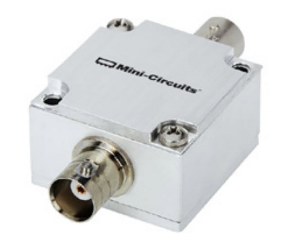 (Image source: Minicircuits website)
By the end of this blog post, you should have some confidence to be able to build your own; perhaps not to the same spec, but at least it won’t cost $50.
Here is another, far lower-cost, ready-made balun; the Pulse/Yageo CX2045LNL shown in the photo below is intended for 3 MHz to 300 MHz operation and has an impedance transformation ratio of 1:2.
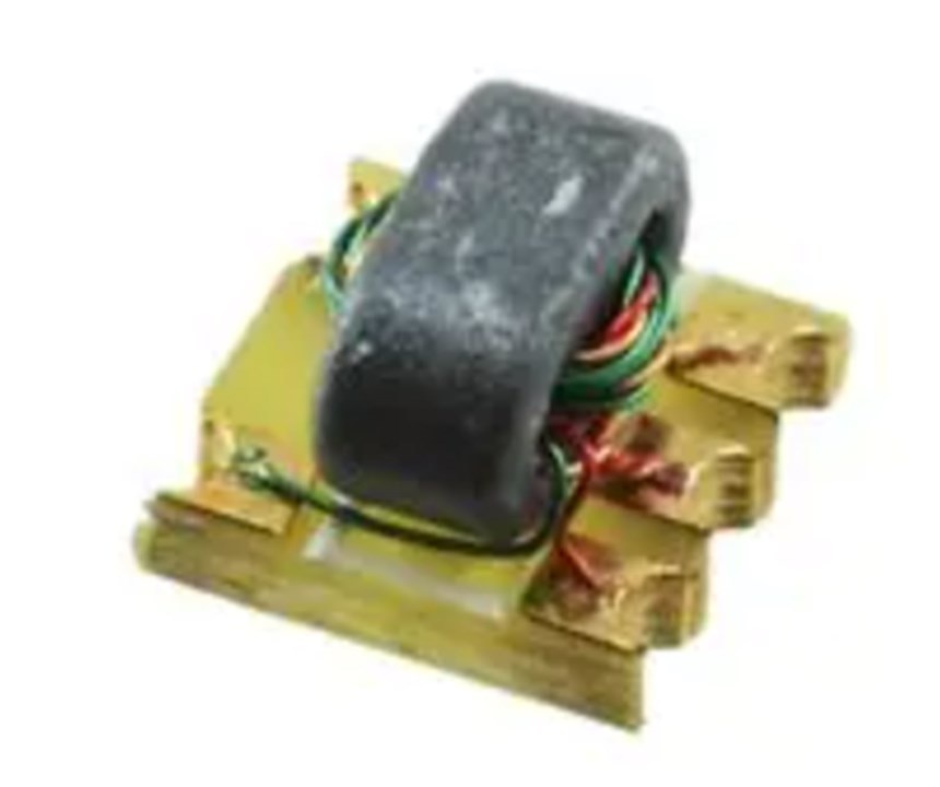 (Image source: Farnell website)
Note that not all baluns will be designed with the methods discussed in this blog post; the datasheets won’t mention that, since it’s irrelevant to the black box functionality of the balun. Some baluns might even be designed as normal transformers if they don’t need to be particularly wideband.
Getting Started: Common-Mode, Differential-Mode Currents and Chokes
Gustav Guanella was a Swiss inventor at Brown Boveri (which later became the modern well-known industrial firm called ABB) who developed communications technology, particularly in the 1940's, that is still used today. This blog post focuses on just one of his inventions, an electrical component that on the face of it is little more than wire windings around ferrite material.
In brief, Guanella-based components rely on wound wires, transmission lines, and inductance. This blog post will slowly step through what it is and how it can be used.
The diagram here shows what it's all about. If you had a single wound wire, it would have inductance that results from the magnetic field that the wire exhibits when current passes through it. That's a typical inductor, a single wound coil, that has an impedance that increases as applied AC voltage frequency rises, due to the changing magnetic flux causing a back EMF that reduces the changing current through the coil.
If you have two wires close together, with a source at one end and a load resistance at the other end, then the current that flows through the two wires is symmetrical, the magnetic field is canceled out, and the inductance is therefore greatly reduced. This is represented by the black arrows i1 in the diagram (although not shown, imagine a resistor has been soldered across the wires at the end labeled load); the current travels around the green wire, through the resistor, and then back up the orange wire.
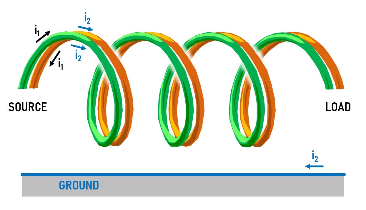
However, if there is a common-mode signal on both wires, represented by i2, you could imagine that a return path could be, for instance, a ground connection (it doesn't have to be ground). Although not shown, that path to the ground could be through (say) stray high resistances, or perhaps capacitance between the wires and the chassis. Since the current is flowing through both wires in the same direction, this unsymmetric common-mode direction does not cancel out the magnetic field, and the two coils act like an inductor to the common-mode signal.
If the two coils were wound around a ferrite material, then the ferrite would absorb some of the energy from the common-mode signal, turning it into heat. The two coils and ferrite would become a common-mode choke, and it would work like this: Any signal i1 would pass through without (significant) loss because of the reduced inductance for differential mode signals as mentioned earlier. RF noise on the other hand (for instance an electromagnetic source, perhaps the switching noise from a DC-DC switching converter) would likely be picked up equally by both wires attached to the source and would be reduced by the choke since that’s a common-mode signal. All of this is a typical use-case for a common-mode choke.
Transmission Lines
The next step of understanding Guanella components is to understand the properties of parallel (or twisted, or coax) wires. If wire pairs are placed together 'just right', then their series inductance, and parallel capacitance, together cause the wires to look like pure resistance, until the signal reaches the far end. This is regardless of wire pair length. That pure resistance can be a value of 50 ohms with real-world wire and insulation diameters, with little effort. Other values are possible too, by changing the wire or insulation thicknesses and the spacing between the pair. Whatever the value, it is known as the characteristic impedance of the wire pair. The wire pair is known as a transmission line. When you buy 50-ohm coax cable, you're buying a transmission line with a characteristic impedance of 50 ohms.
You can consider for all intents and purposes, that if you have any length of 50-ohm coax cable, then the core and shield at one end will behave exactly like a 50-ohm resistor, at least until the signal has had time to travel to the end of the coax (through the distributed capacitance and inductance of the coax) and reflect back from the disconnected far end. If the end of the coax is connected to a real 50-ohm resistor, then the coax will always look like a 50-ohm resistor to the source. There is a very popular video that elaborates on a thought experiment (it is possible to perform similar experiments and the result would be the same), using pairs of wires and a lightbulb; the lightbulb illuminates almost immediately because the pairs of wires look like a (relatively low) resistance immediately: https://www.youtube.com/watch?v=bHIhgxav9LY
All of the above means that if the load resistance matches the transmission line characteristic impedance, then the source will see a pure resistance, regardless of the length of the transmission line, and (as has been deduced above) there will be no impact if the transmission line is wound in a coil and regardless of if it is wound around a ferrite material.
The load resistance could be a real 50-ohm resistor; you can buy them mounted inside a coax terminator, or you could solder a normal 50-ohm resistor to act as the load.
Putting It Together: The ‘Coil System’
To summarize so far, the two close wires wound around a ferrite core, act as if it were just two normal wires with little inductance, for symmetric current flows, but act like a choke for asymmetric current flow. The cool thing is that by using the transmission line effect, for symmetric current flow, the winding, ferrite, and load resistance all together just look like a single pure resistance.
Rephrasing yet again, the whole thing looks like a 50-ohm resistor. Measuring with a multimeter will of course result in a reading of 50 ohms since that is what the load resistance is, but if you applied an AC signal, you would still see a load of 50 ohms, whereas one would expect the impedance to be higher due to inductance if the two windings were separated. So, the Guanella component so far acts like a pure 50-ohm resistor for symmetric signals but acts like a high impedance for asymmetric signals. This is almost like a transformer (apart from the transmission line delay) since the high impedance is isolation. Of course, this isolation is really only for AC, because a choke doesn't block DC.
You can do some very cool stuff with such a component that behaves like a pure resistor combined with transformer-type isolation, although really it is a pair of windings and ferrite. The ferrite could be in rod form, or it could be a toroid, or multi-aperture (for instance binocular-shaped).
Guanella referred to his component (consisting of the wire pair and the ferrite material) as a Coil System and it can also be referred to as a Balun, a term that as mentioned earlier means BALanced-UNbalanced, because you can use it to interwork a balanced signal to an unbalanced (e.g. ground-referenced) signal or vice-versa.
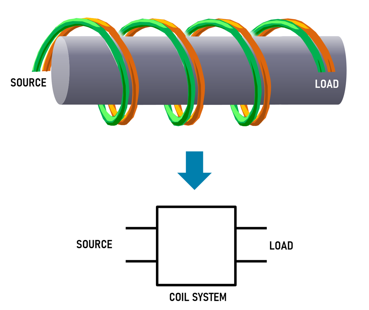
In the diagram above, the source impedance equals the characteristic impedance of the transmission line, and the load impedance would need to be set to the same value too.
Multiple Coil Systems
The diagram below shows an example of how two of the coil systems can be combined to serve a useful purpose. The topology is such that the left sides of the coil systems are wired in series, but the right sides are wired in parallel. If the transmission line impedance is 50 ohms, then the left side can be used to match a 100-ohm impedance with a 25-ohm impedance on the right side. The impedance transformation occurs with no loss since symmetric signals can pass through the coil system with no loss. This impedance transformation can theoretically occur for any frequency input signal since the analysis has already determined that for symmetric signals, there is little inductance; the whole system is wideband.
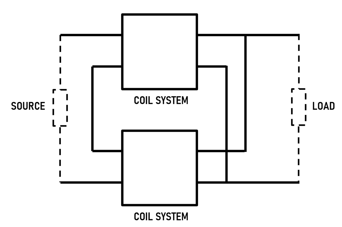
This transformation is extremely handy for matching antennas to radio transmitters or receivers that may need to be tuned across a wide range (if the radio is only intended for operating at a single frequency, then an LC circuit could be used to perform the matching instead; sometimes a tuneable LC circuit is used). Another important point with the Guanella component designed solution is that, as mentioned earlier, the AC isolation allows unbalanced output circuitry to be transformed into a balanced output.
You could combine additional coil systems to achieve different impedance transformations. For instance, if you had four coil systems all in series on the input side, and all in parallel on the output side, then that would be useful for conversion from 200 ohm to 12.5 ohm if the characteristic impedance of the transmission lines was 50 ohms. Incidentally, you can always work out the required characteristic impedance, by using this quick formula (it is the geometric mean formula, different from the arithmetic mean!):
Z0 = sqrt(Z1 * Z2) where Z1 and Z2 are the input and output impedances respectively.
What if you wanted a conversion from 300 ohms to approximately 19 ohms? The solution there would be to still use four coil systems, but loosen the spacing between the wires inside each coil system slightly, so that the characteristic impedance is raised from 50 ohms to 75 ohms.
Generalizing this concept, you can see that by combining n coil systems in series on the left side, and in parallel on the right side, you can perform impedance transformations with ratios of n^2:1 with an impedance of n*Z0 on the left side, and (1/n)*Z0 on the right side, where Z0 can be in the approximate range of 30-120 ohms, for real-world wire and insulation dimensions.
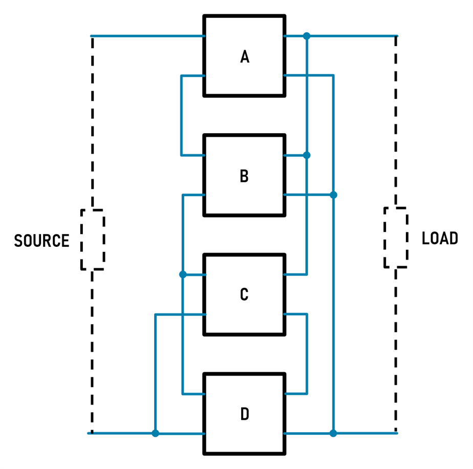
In 1972, Donald McClure used Guanella coil systems to come up with a whole range of combinations that provide a variety of transformation ratios other than n+2:1.
His method relies on the observation that for useful configurations you could always connect the left sides in parallel or series, provided you connect the other sides in the opposite manner. Here's an example that provides an impedance transformation of 6.25:1 (i.e. 50 ohms to 8 ohms if the characteristic impedances of the pairs of wires is 20 ohm) and if you look at the coil systems labeled A and B, you can see they are wired in series on the left side but are wired in the opposite manner i.e. parallel, on the right side. Similarly, coil systems C and D are in parallel on the left side, and in series on the right side. Group AB is in series with group CD on the left side, but group AB is in parallel with group CD on the right side.
Donald McClure used his own unique notation to describe the configurations. For instance, the above configuration left side would be described as:
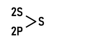
In the above notation 2S means that two coil systems are connected in series, 2P means two coil systems are connected in parallel, and the S means that the resultant subsystems from the previous step are connected in series. The right side can be described by replacing P with S and vice-versa.
It appears that the McClure table of configurations has only ever been published (beyond the original patent information) in a trade journal called RF Design, in February 1994 page 65, and this is available to view at the Internet Archive, and I don't want to provide a screenshot here in case there is still a copyright on it.
Real-World Baluns
In practice, baluns can be made in many different ways. One popular method is to use coax cable to act as the pair of wires, and some designs will thread the coax through a tunnel formed from a load of ferrite toroids, in part because that’s often easier to do than to wrap coax around a ferrite core.
Another method is to use two parallel wires, or alternatively twisted wires, and then thread them through a toroid multiple times. In both cases, the aim is to try to suppress all common-mode signals while allowing all differential-mode signals to pass through the transmission line.
High-Level Calculations
If you wanted to build a balun, the high-level calculations are not too difficult. Note: in practice, you may find things need to be tweaked a bit. For instance, it is an assumption that the characteristic impedance does not change when the wire pair is wrapped around ferrite; in practice, there is a very slight change.
The high-level aim would be to obtain a transmission line with the characteristic impedance you desire (e.g. 50 ohms coax, or say 100 ohms twisted wires stripped from Ethernet cable, or twist or parallel wires yourself), and then bring about a situation (for example with ferrites) where the impedance is much higher (say at the very least 10 times, but more preferably 20 times or more) for the frequencies that you wish to use the balun at. Here’s a worked example, where the assumption is that a 50-ohm impedance balun is needed to work for 30 MHz signals and beyond (in practice, it’s not unusual for the balun to operate at 10 times the minimum frequency, or even more, so the balun being designed here may well function to beyond 300 MHz).
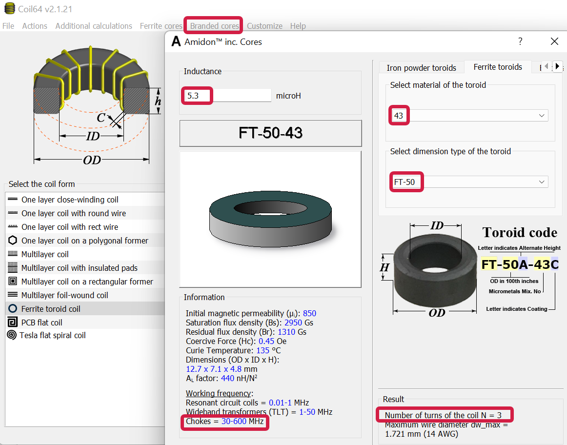
The choke impedance should be at least 500 ohms, but a minimum of 1000 ohm will be much better, so let's use that. The inductance needs to be determined. At 30 MHz, an inductance of 5.3 uH will provide an impedance of 1000 ohm (impedance = 2 * pi * freq * inductance).
Next, a ferrite core or toroid could be selected. There are hundreds of toroid options, so that will be used in this example. The excellent coil64 program can be used to select a toroid. The dimensions of it need to suit the transmission line; for instance, a thick coax might not fit a small toroid. In addition, you’d check that the toroid is suitable for acting as a choke at the frequencies of interest, by seeing what the Coil64 program states as shown in the screenshot below. The program will indicate the number of turns that will provide the desired inductance. In this example, if an FT-50-43 toroid was used, then the transmission line would need to be looped through the ferrite three times (the Coil64 software is accurate, but ferrites are not : ) also, it’s an integer result; personally, I would use an extra turn, in this case, to provide more confidence that the desired minimum inductance is present).
That’s it; the balun has been designed! In practice, as mentioned, if the coax is too thick to wrap around the ferrite, you could use several ferrites and thread the coax just through the middle.
Parallel and Twisted Wires
Coax is already conveniently available in 50-ohm and 75-ohm versions. For parallel or twisted pairs of wires, it is harder to calculate the characteristic impedance, however, some guidelines are suggested here (I’ll update or add to this list if people have better real-world experience and can provide advice in the comments):
For 100 ohm characteristic impedance, the easiest method would be to use ready-twisted-pair wire from Ethernet cables.
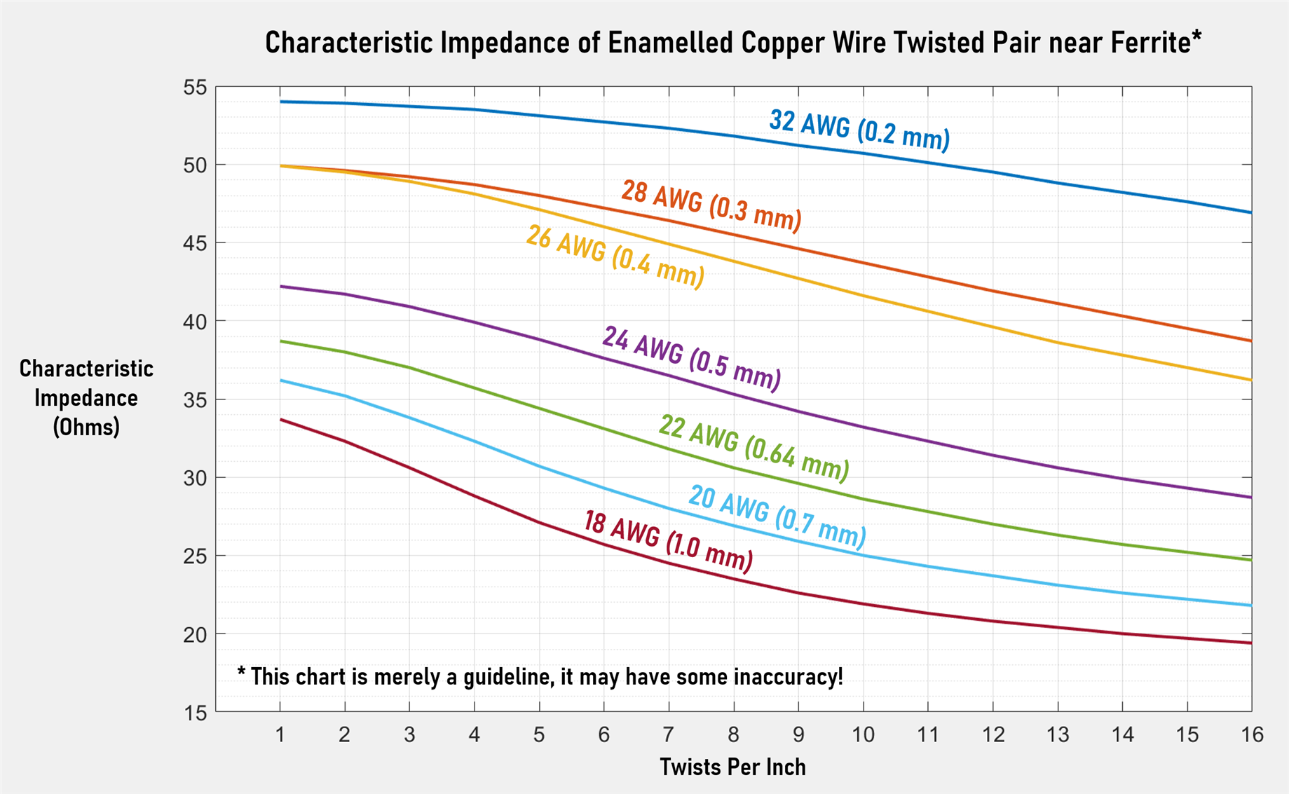
For 50 ohm, if you’re using enameled copper wire, here are the suggestions:
For 32 AWG (0.2 mm diameter) wire, you can twist the wire at about 10 twists per inch, or alternatively if you can place untwisted wires against each other side-by-side, then the impedance will be acceptable at just over 50 ohms. You can buy ready-paired wire glued together; it’s called bifilar wire.
For 28 AWG (0.3 mm), a few twists per inch (perhaps 3 twists per inch) is suggested; you could also use parallel untwisted wires (bifilar).
For 26 AWG (0.4 mm) wire: No more than 2 twists per inch; parallel (bifilar) wire is fine too.
For 24 AWG (0.5 mm), parallel wire is acceptable, providing a characteristic impedance of just under 50 ohms; if there are any twists, then the characteristic impedance will drop to 40 ohms if the twisting is about 2 twists per inch.
What if a different characteristic impedance is needed? For instance, if you're combining Coil Systems in order to perform impedance conversion? In that case, the chart below might help as a starting point, however, I have based it on 'finger in the air' values, plugged into work titled Twisted Pair Transmission Line by Peter Lefferson. If anyone has different real-world values, even a single data point or two, then please let me know in the comments, and I can use that to refine all the data points for the entire chart. See further below for an experimental Excel file if you wish to try other values. I don't guarantee that to be accurate either; please let me know if you think anything in it needs changing.
Useful Resources
If you want to make your own baluns or see how baluns are practically used, the following web links have been recommended to me; and from what I can tell, the information is good:
https://www.dj0ip.de/balun-stuff/
https://www.g0ksc.co.uk/construction/creatingabalun.html
http://www.karinya.net/g3txq/baluns/baluns.pdf
Summary
This blog post discussed what the Guanella component is, how it can be used as a balun, and how it can be used for impedance transformation, as well as how to design it at least to a reasonable high level, ready for testing or use. Eventually, in a later blog post I'll create some baluns and write up experiments with them, but it would be interesting to hear about other people’s experiments or experiences with such devices too.
Thanks for reading!
-

jc2048
-
Cancel
-
Vote Up
0
Vote Down
-
-
Sign in to reply
-
More
-
Cancel
-

jc2048
in reply to jc2048
-
Cancel
-
Vote Up
0
Vote Down
-
-
Sign in to reply
-
More
-
Cancel
-

shabaz
in reply to jc2048
-
Cancel
-
Vote Up
0
Vote Down
-
-
Sign in to reply
-
More
-
Cancel
Comment-

shabaz
in reply to jc2048
-
Cancel
-
Vote Up
0
Vote Down
-
-
Sign in to reply
-
More
-
Cancel
Children