element14 Community
element14 Community
    Register Log In
  • Site
  • Search
  • Log In Register
  • About Us
  • Community Hub
    Community Hub
    • What's New on element14
    • Feedback and Support
    • Benefits of Membership
    • Personal Blogs
    • Members Area
    • Achievement Levels
  • Learn
    Learn
    • Ask an Expert
    • eBooks
    • element14 presents
    • Learning Center
    • Tech Spotlight
    • STEM Academy
    • Webinars, Training and Events
    • Learning Groups
  • Technologies
    Technologies
    • 3D Printing
    • FPGA
    • Industrial Automation
    • Internet of Things
    • Power & Energy
    • Sensors
    • Technology Groups
  • Challenges & Projects
    Challenges & Projects
    • Design Challenges
    • element14 presents Projects
    • Project14
    • Arduino Projects
    • Raspberry Pi Projects
    • Project Groups
  • Products
    Products
    • Arduino
    • Avnet Boards Community
    • Dev Tools
    • Manufacturers
    • Multicomp Pro
    • Product Groups
    • Raspberry Pi
    • RoadTests & Reviews
  • Store
    Store
    • Visit Your Store
    • Choose another store...
      • Europe
      •  Austria (German)
      •  Belgium (Dutch, French)
      •  Bulgaria (Bulgarian)
      •  Czech Republic (Czech)
      •  Denmark (Danish)
      •  Estonia (Estonian)
      •  Finland (Finnish)
      •  France (French)
      •  Germany (German)
      •  Hungary (Hungarian)
      •  Ireland
      •  Israel
      •  Italy (Italian)
      •  Latvia (Latvian)
      •  
      •  Lithuania (Lithuanian)
      •  Netherlands (Dutch)
      •  Norway (Norwegian)
      •  Poland (Polish)
      •  Portugal (Portuguese)
      •  Romania (Romanian)
      •  Russia (Russian)
      •  Slovakia (Slovak)
      •  Slovenia (Slovenian)
      •  Spain (Spanish)
      •  Sweden (Swedish)
      •  Switzerland(German, French)
      •  Turkey (Turkish)
      •  United Kingdom
      • Asia Pacific
      •  Australia
      •  China
      •  Hong Kong
      •  India
      •  Korea (Korean)
      •  Malaysia
      •  New Zealand
      •  Philippines
      •  Singapore
      •  Taiwan
      •  Thailand (Thai)
      • Americas
      •  Brazil (Portuguese)
      •  Canada
      •  Mexico (Spanish)
      •  United States
      Can't find the country/region you're looking for? Visit our export site or find a local distributor.
  • Translate
  • Profile
  • Settings
Test & Tools
  • Technologies
  • More
Test & Tools
Blog Vector Network Analyzers for the General Reader, Part 3: Using a Commercial Calibration Kit
  • Blog
  • Forum
  • Documents
  • Files
  • Members
  • Mentions
  • Sub-Groups
  • Tags
  • More
  • Cancel
  • New
Join Test & Tools to participate - click to join for free!
  • Share
  • More
  • Cancel
Group Actions
  • Group RSS
  • More
  • Cancel
Engagement
  • Author Author: shabaz
  • Date Created: 5 Mar 2024 5:57 PM Date Created
  • Views 1814 views
  • Likes 8 likes
  • Comments 6 comments
  • VNA calibration standards
  • sdr-kits
  • Smith chart
  • vector network analyzer
  • impedance
  • fpc1000
  • vna
  • rf
  • fpc1500
Related
Recommended

Vector Network Analyzers for the General Reader, Part 3: Using a Commercial Calibration Kit

shabaz
shabaz
5 Mar 2024

Table of Contents

  • Introduction
  • What’s in the Box?
  • Interpreting and Using the Datasheet
  • Performing the Calibration
  • Testing the Calibration
  • Summary


Introduction

In a couple of earlier blog posts ( Vector Network Analyzer (VNA): A Practical Getting-Started Guide for the General Reader  and  Vector Network Analyzers for the General Reader, Part 2: Inductance Measurement! ), the use of a Vector Network Analyzer was introduced in a practical, no-maths manner, and it was demonstrated how the VNA could be set up to produce decent measurements using DIY ‘Open/Short/Load’ standards. The purpose of the Open/Short/Load components is to remove the effects of connecting cables from the measurement of the device-under-test. VNAs measure the phase and amplitude of signals, and therefore it’s very important to remove the delay and loss of the cables, otherwise the results will be misleading and highly incorrect.

The simple DIY method is totally fine for measurements up to a few hundred MHz, but a commercial kit is highly desirable beyond this. This blog post discusses how I went about using a (relatively) low-cost commercial kit.
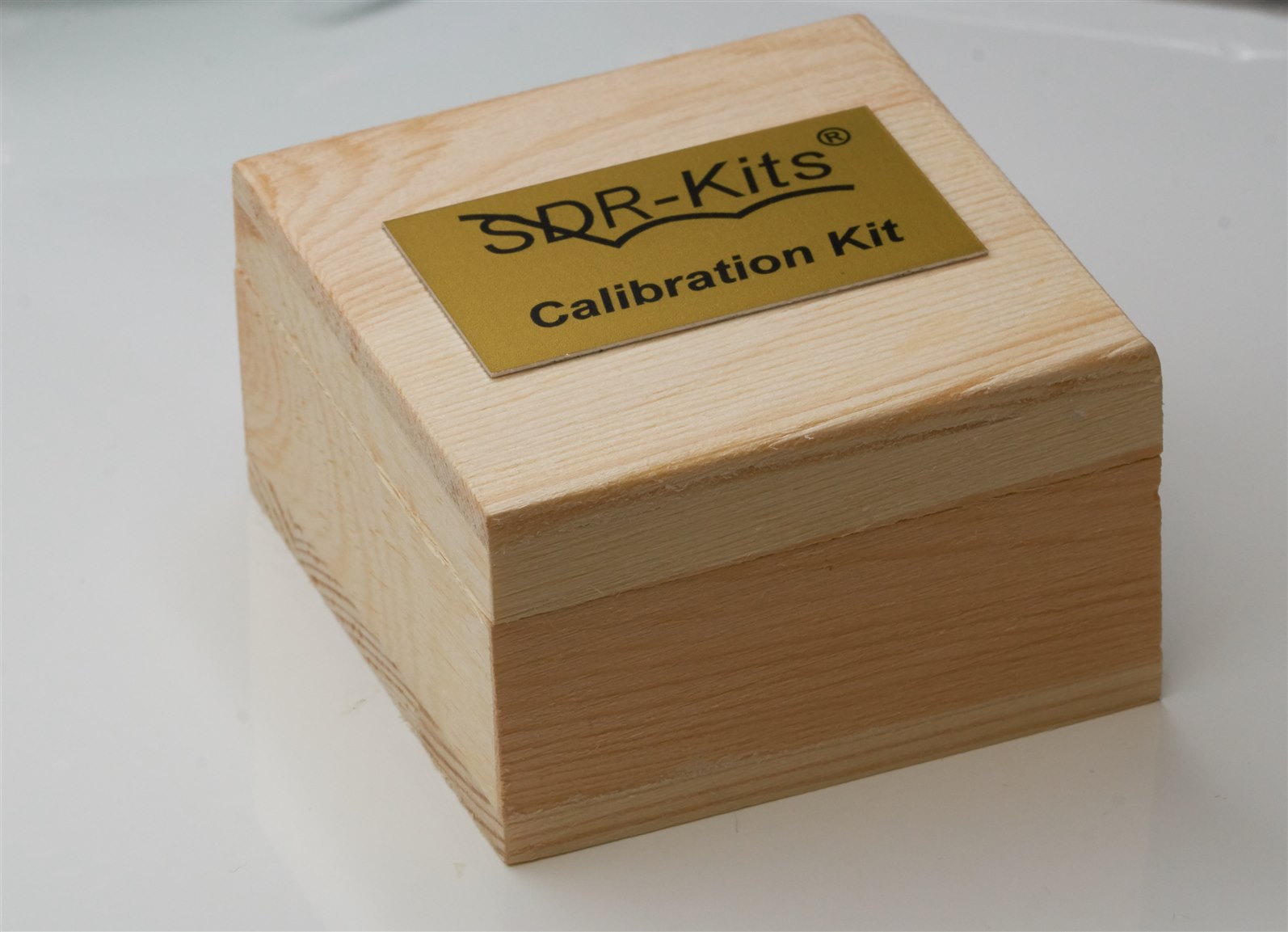
image

What’s in the Box?

I purchased a Female SMA calibration kit because it suits my needs better. I tend to connect an SMA male-to-male cable on my VNA, so the device under test will either have an SMA female connector on the end, or I will extend the reference plane using a short length of cable with an SMA female connector on it.

The box contains four components, and the load impedance is labeled. In my case, it is 48.52 ohm (which I was not happy with, but fortunately, that is solvable with no waste; it is discussed further below!).

image

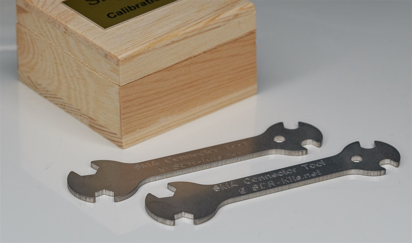
While I was at it, I also purchased a couple of spanners/wrenches (it’s a pity the calibration kit box isn’t large enough to store these, too!):

image

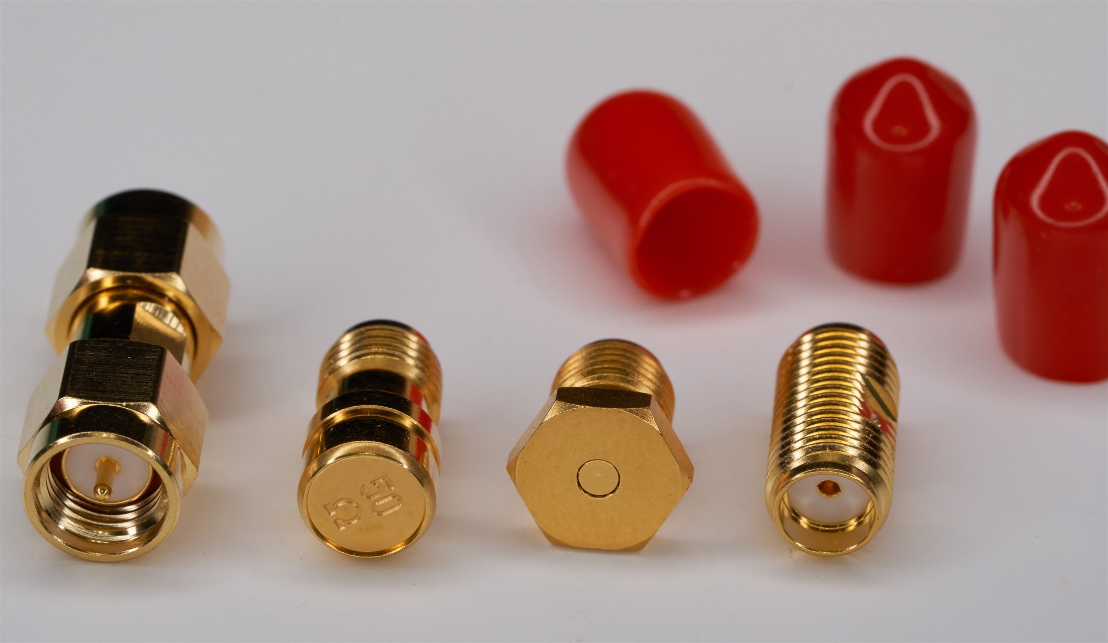
Here’s a more close-up photo of what’s supplied; from left to right, there is:

(a) Male-to-Male adapter (I won’t use this much)
(b) 50-ohm nominal load, with the precise impedance labeled inside the storage box
(c) SMA short (zero ohm)
(d) Female-to-Female adapter, which doubles as a SMA open.

image

Of course, the price (£60+tax) is more for the supplied calibration values and not the actual components (although they need to be good enough to be repeatably used).

The box comes with a printed sheet of paper, which is also downloadable (Cal Kit PDF datasheet).

Interpreting and Using the Datasheet

The supplied datasheet is targeted toward a particular VNA (called VNWA), so initially, take some time to read it carefully, but it's not too difficult to make sense of (the author of the datasheet, Kurt Poulsen, was very helpful) for applying toward any VNA model.

The key information is related to the offset delays. From the datasheet, they are:

Open (Female-to-Female Adapter): 42.35 ps for VHF, 42.3 ps for 1 MHz.

Short: 26.91 ps

Through (Female-to-Female Adapter): 42.43 ps

The VNA indicated in the datasheet (VNWA) happens to use negative two-way delay values for the Open and Short settings, so the values above need to be multiplied by minus two to use that VNA (for the Through setting, no multiplication is done). In other words, when using the VNWA with that Female SMA calibration kit, you would use the following settings:

Open: -84.7 ps for VHF, -84.6 ps for 1 MHz

Short: -53.82 ps

Through: 42.43 ps

Follow the datasheet to populate the correct fields.

image

Some VNAs do not use doubled-up values. The VNA I was using (FPC1500) uses one-way delays.

If the VNA requires electrical length values (i.e. mm length values instead of delay in ps), then you’ll need to multiply by 0.3. The FPC 1500 requires one-way positive electrical length values, so multiplying by 0.3, I get:

Open: 12.705 mm for VHF, 12.69 mm for 1 MHz

Short: 8.073 mm

Through: 12.729 mm

Enter the values into the VNA calibration standards configuration screen.

image

Performing the Calibration

Now that the VNA is configured, you’re ready to perform the calibration! Using the best SMA cable you can find (ideally a semi-rigid cable), attach the cable to Port 1 (the connector used for reflection measurements) on the VNA, and hit the buttons in the menu to initiate the calibration sequence. Attach the open/short/load calibration standards when prompted.

image

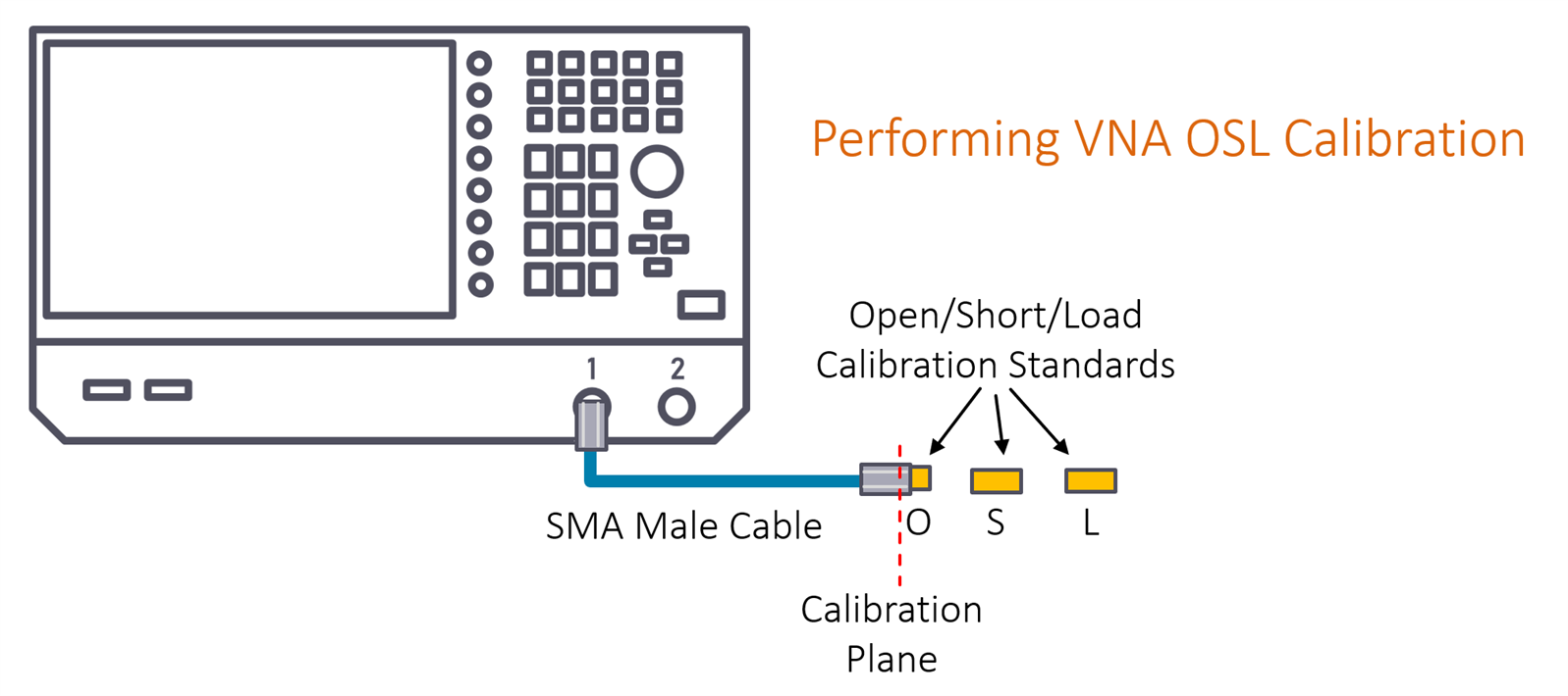
You can now remove the final calibration standard, and the VNA is now ready for device-under-test (DUT) measurements at the calibration plane indicated in the diagram above. If the DUT does not have a SMA connector, then you’ll need to attach another cable to the end of the SMA male cable, and then perform an operation that effectively moves the plane from the calibration point to further down to the end of the newly attached cable. How to do that is covered in the earlier blog posts, so it won’t be repeated here.

Testing the Calibration

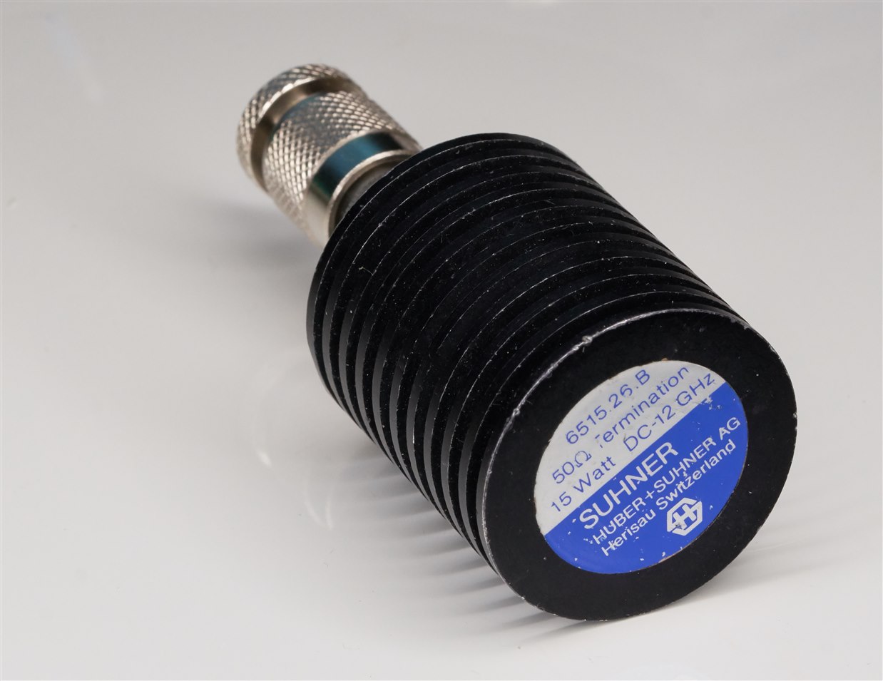
One way to to test that the calibration is good is to attach a known impedance to the VNA. I happen to have a very high-quality 50 ohm load, so I used that as the device under test.

image

Here is the measurement of it as a DUT; the VNA is set to measure from 10 MHz to 3 GHz:

image

A high-quality 50-ohm DUT load should look like a single dot at the center of the Smith chart for the entire frequency range. In the screenshot above, that’s not what is seen. There’s a tiny circular shape, starting (at 10 MHz) near the center, but then the shape curves southward and loops around a bit.

Either the 50-ohm DUT is not as good as hoped, or the calibration is not as good as desired. I was initially unhappy with the calibration kit because the supplied 50-ohm standard was actually labelled 48.52 ohm, which is quite a significant discrepancy. Some VNAs will allow the user to enter the precise value as part of the calibration standards configuration, but the VNA I was using doesn’t allow that.

The solution is actually simple and not bad at all. The solution is to simply buy a better 50-ohm load to replace the one supplied in the kit. A decent 50 ohm SMA load (PDF datasheet) is available for about £20. The original one supplied with the kit doesn’t need to be thrown away; it can be used as a verification DUT/standard instead. No waste! : ) 

Here’s what happens when the calibration is done as before, but this time using the decent 50-ohm load as the 50-ohm calibration standard and then measuring the 48.52-ohm component as a verification DUT:

image

Now it can be seen that the measurement varies very little across the 10 MHz to 3 GHz range, i.e. the verification DUT looks reasonably closely like a ~48 ohm resistance.

Over the years, clever techniques have been developed to better determine the calibration's accuracy. If you're interested, it is highly worth reading a transmission line mathematics PDF document; it is easy to read (some of the math can be skipped). The calibration kit datasheet author Kurt Poulsen recommended this document to me, which he also is the author of, and it's excellent. For a vast collection of VNA literature by Kurt Poulsen, the repository here is well worth checking out.

Summary

The SDR-Kits set is one of the lowest-price calibration kits available, and it seems pretty reasonable! The 50-ohm load wasn’t fit for purpose (at least, not with all VNAs), and I didn’t like that it was cylindrical (with no flats for a spanner/wrench). Fortunately, those issues are easy to solve by purchasing a 50-ohm load and then using the supplied one as a verification device instead.

Proper calibration will increase confidence when performing measurements beyond a few hundred MHz.

In the next blog, I’ll (partially) cover SMA cables!

Thanks for reading.

  • Sign in to reply
  • shabaz
    shabaz over 1 year ago in reply to Tigerzhou

    Thanks!

    • Cancel
    • Vote Up 0 Vote Down
    • Sign in to reply
    • More
    • Cancel
  • Tigerzhou
    Tigerzhou over 1 year ago

    this blog is really outstanding, thanks a lot for your efforts to share your insights.

    • Cancel
    • Vote Up 0 Vote Down
    • Sign in to reply
    • More
    • Cancel
  • shabaz
    shabaz over 1 year ago

    Problem solved with the new 50 ohm load! This is the part code mentioned in the blog post; figured I'd take a photo in case there's ever a need to identify what the genuine MiniCircuits part should look like:

    image

    Now the cal kit is totally usable with any VNA, using the earlier load as a verification device instead:

    image

    • Cancel
    • Vote Up 0 Vote Down
    • Sign in to reply
    • More
    • Cancel
  • shabaz
    shabaz over 1 year ago

    A directory scan of the documents written by Kurt Poulsen, available in a couple of zip files at the VNA literature link mentioned above. It's impressive. The few I checked out, are very easy to read, and have good photos to explain things.


    KURT_OZ7OU_COLLECTION_PART1
    │ Collection Part1 Version 0.01.txt
    │ Readme.txt
    │
    └───Calibration
    │ 26cm UT141A behaviour.pdf
    │ BNC-male-female-REV1.zip
    │ Calibration Kit File for R&S FSH-Z29.pdf
    │ Comparison between VNWA and FA-VA5 calibrations.pdf
    │ Conversion_of_VNWA_format_to_L-C_coeffecients.pdf
    │ embedding_ deutsch_rev.pdf
    │ Finding the complex impedance of the female female test adaptor.pdf
    │ How to calibrate and measure a DUT like a toroid correctly the smart way.pdf
    │ How to calibrate and measure a DUT like a toroid correctly.pdf
    │ How to calibrate and measure a DUT like a toroid in shunt mode.pdf
    │ How to calibrate and measure a DUT like a toroid in shunt mode_2.pdf
    │ How to characterize a SMA test adaptor the hard way.pdf
    │ How to convert a VNWA calibration kit file for use by other VNA type.pdf
    │ How to create a VNWA calibration kit file for the R&S ZV-ZCAN male and female 50 Ohm version.pdf
    │ How to de-embed a unknow two port device.pdf
    │ How to deembed a thru element connected in series with a passive DUT.pdf
    │ How to extend the frequency range for measurement of a calibration kit.pdf
    │ How to fabricate a N Male and Female calibration kit rev2.pdf
    │ How to measure on SOL calibration kits_REV1-deutsch.pdf
    │ How to measure on SOL calibration kits_REV1.pdf
    │ How to measure on SOL calibration kits_REV1.txt
    │ How to perform a T-Check for a VNWA Calibration_Final.pdf
    │ How to perform a T-Check for a VNWA Calibration_Final.txt
    │ How To Test a Calibration using a Rigid line with known K factors.pdf
    │ How to top tune your SDR Kits male and female calibration kit of Rosenberger parts-Rev2-deutsch.pdf
    │ How to top tune your SDR Kits male and female calibration kit of Rosenberger parts_rev2.pdf
    │ How to understand VNWA and FA-VA5 calibration.pdf
    │ How to use and verify HP35033C.pdf
    │ How to use FEMM for an already created model.pdf
    │ How to utilize an SDR-Kits BNC calibration kit for a R&S VNA_REV1.pdf
    │ How to verify the calibration quality of a VNA and the calibration kit used.pdf
    │ HowToEnterTheLoadResistanceValueForAnSDR-KitsCalibrationKitBasedOnRosenbergerParts.pdf
    │ IMG_0619.jpg
    │ IMG_0630.jpg
    │ Links to May 2017 calibration kit-1.pdf
    │ Measurements on the Amphenol Connex male and female calibration kit.pdf
    │ Measurements on the SDR-Kits mixed Male Calibration Kit .pdf
    │ Report_on_using_the_SMA_Female_as_open_adaptor.pdf
    │ SDR Kits male and female calibration kit L and C coefficients to 6 GHz.pdf
    │ Some basic knowledge about a transmission line.pdf
    │ Some basic knowledge about a transmission line.txt
    │ T-Check.pdf
    │ Test of the load from SDR-Kits BNC calibration kit.pdf
    │ UT141A fringe C.pdf
    │
    ├───50 Ohm 4 Point SMA Tester
    │ 4 Point SMA Tester.txt
    │ 4 Point SMA Tester_Basic Concept.pdf
    │ 4 Point SMA Tester_V2.pdf
    │ 4 Point SMA Tester_V4_Adaptors.zip
    │ Instruction for use of SMA Load Testbox version 4.pdf
    │ Instruction for use of SMA Load Testbox-1.pdf
    │ Instruction for use of SMA Load Testbox.pdf
    │ Instruction for use of SMA Load Testbox.zip
    │
    ├───Calibration Standards
    │ Amphenol Connex Cal standards_rev3.pdf
    │ Amphenol Connex Cal standards_rev3_German.pdf
    │ Amphenol Connex Cal standards_rev4-Deutsch.pdf
    │ Amphenol Connex Cal standards_rev4_page2-Deutsch.pdf
    │ Amphenol_Cal_Standards_rev5.pdf
    │ Rosenberger Cal standards_rev2.pdf
    │ Rosenberger Cal standards_rev2_German.pdf
    │ Rosenberger Cal standards_rev3.pdf
    │ Rosenberger Cal standards_rev4-Deutsch.pdf
    │ Rosenberger Cal standards_rev5_page1.pdf
    │ Rosenberger Cal standards_rev5_page2.pdf
    │ Rosenberger female and male calibration kit for HP VNA’s to 8GHz.pdf
    │ Rosenberger_Fairview male Cal standards-Deutsch.pdf
    │ Rosenberger_Fairview male Cal standards_rev1_page1.pdf
    │ Rosenberger_Fairview male Cal standards_rev1_page2.pdf
    │ Rosenberger_Fairview_Male_Cal_Standards_rev1-1.pdf
    │ Rosenberger_Female_Cal_Standards_rev5-2.pdf
    │
    └───Spectrum Analyzer mode
    How to calibrate the VNWA sensitivity in Spectrum Analyzer mode.pdf
    How to calibrate the VNWA Spectrum Analyzer using the TX output as signal source.pdf


    KURT_OZ7OU_COLLECTION_PART2
    │ Collection Part2 Version 0.01.txt
    │ Readme.txt
    │
    ├───other things
    │ CRTU_RU mixer measurement.pdf
    │ DG8SAQ_Multiport_V1.pdf
    │ Extensive test of the N2PK RF REV2.pdf
    │ FEMM Microstrip line simulation.pdf
    │ FEMM Microstrip line simulation_rev1.pdf
    │ How to use FEMM for an already created model.pdf
    │ Test set for DG8SAQ VNWA.pdf
    │ Why to use the FA-VA5 unmodified.pdf
    │
    ├───various measurements with VNWA
    │ │ Analyze of a 25cm long UT141 rigid cable.pdf
    │ │ Crystal Test Fixture for DG8SAQ VNWA and N2PK VNA .pdf
    │ │ Crystal Test Fixture for DG8SAQ VNWA and N2PK VNA .txt
    │ │ Crystal Test Fixture for DG8SAQ VNWA and N2PK VNA_deutsch.pdf
    │ │ How to measure a coil in transmission mode.pdf
    │ │ How to measure filters at around 2.45GHz.pdf
    │ │ How to measure S11 at around 2.45GHz.pdf
    │ │ How to measure the isolation in a Transfer Switch.pdf
    │ │ How to measure the resonance frequency and Q of an air coil-rev1.pdf
    │ │ How to measure the resonance frequency and Q of an air coil.pdf
    │ │ How to measure the resonance frequency and Q of an air coil.txt
    │ │ How to measure very high impedances-Deutsch DG3OK.pdf
    │ │ How to measure very high impedances.pdf
    │ │ How to perform a T-Check for a VNWA Calibration.pdf
    │ │ How_to_derive_the_k_factors_for_an_unknown_semirigid_cable_of_type_UT141A_rev1.pdf
    │ │ Investigation of Leobodnar GPSDO_rev2.pdf
    │ │ Investigation of Leobodnar GPSDO_rev2.txt
    │ │ Measurement of a 6 cavity duplex filter of brand Procom and type DP2-6S.pdf
    │ │ Measurement of velocity factor VF for 300 ohm twin lead cable.pdf
    │ │ Measurement of velocity factor VF for 300 ohm twin lead cable_deutsch.pdf
    │ │ Measurement of velocity factor VF for 300 ohm twin lead cable_V2.pdf
    │ │ Measurement of velocity factor VF for 300 ohm twin lead cable_V2.txt
    │ │ Measurement of velocity factor VF for 300 ohm twin lead cable_V2_deutsch.pdf
    │ │ Resistor measurements with a VNA-deutsch.pdf
    │ │ Resistor measurements with a VNA.pdf
    │ │ Resistor measurements with a VNA.txt
    │ │ Universal test adaptor.pdf
    │ │ VNWA measurements of PA output Z.pdf
    │ │ VNWA_Experiments.pdf
    │ │
    │ ├───Power Sweep
    │ │ How to use the new VNWA Power Sweep Utility for S11 measurements.pdf
    │ │ How to use the new VNWA Power Sweep Utility_rev1.pdf
    │ │
    │ └───Y S21 Method
    │ Test of the Y S21 method.pdf
    │ Y S21 Method custom traces.zip
    │ Y S21 Method.txt
    │
    └───VNWA
    How to add a power trace to the VNWA in spectrum analyzer mode.pdf
    How to improve the Dynamic Range of the VNWA Using Averaging and Smoothing.pdf
    How to measure accurate with VNWA for two port devices.pdf
    How to measure the isolation in a Transfer Switch.pdf
    How to Operate VNWA2 and VNWA3 Remotely Wired or Wireless.pdf
    How to properly set the VNWA for use of the VNWA Frequency meter.pdf
    How_to_setup_a_custom_background_image.pdf
    Power trace in the SA mode new proposal about sa_offset as custom variable.pdf
    RF Generator-Output-VNWA3-and VNWA2 rev1.pdf
    RF Generator-Output-VNWA3-and VNWA2 rev1.txt
    RF Generator-Output-VNWA3-version-35.2.u.pdf
    The spectrum for VNWA2 and VNWA3 pending frequency and multiplier settings.pdf
    USBView-deutsch_rev1.pdf
    VNWA multiplier settings and spectrum around 83MHz.pdf
    Why VNWA2 and VNWA3 does not show correct attenuation of high and lowpass filters.pdf
    • Cancel
    • Vote Up 0 Vote Down
    • Sign in to reply
    • More
    • Cancel
  • DAB
    DAB over 1 year ago

    Very informative and well written.

    • Cancel
    • Vote Up 0 Vote Down
    • Sign in to reply
    • More
    • Cancel
>
element14 Community

element14 is the first online community specifically for engineers. Connect with your peers and get expert answers to your questions.

  • Members
  • Learn
  • Technologies
  • Challenges & Projects
  • Products
  • Store
  • About Us
  • Feedback & Support
  • FAQs
  • Terms of Use
  • Privacy Policy
  • Legal and Copyright Notices
  • Sitemap
  • Cookies

An Avnet Company © 2025 Premier Farnell Limited. All Rights Reserved.

Premier Farnell Ltd, registered in England and Wales (no 00876412), registered office: Farnell House, Forge Lane, Leeds LS12 2NE.

ICP 备案号 10220084.

Follow element14

  • X
  • Facebook
  • linkedin
  • YouTube