element14 Community
element14 Community
    Register Log In
  • Site
  • Search
  • Log In Register
  • About Us
  • Community Hub
    Community Hub
    • What's New on element14
    • Feedback and Support
    • Benefits of Membership
    • Personal Blogs
    • Members Area
    • Achievement Levels
  • Learn
    Learn
    • Ask an Expert
    • eBooks
    • element14 presents
    • Learning Center
    • Tech Spotlight
    • STEM Academy
    • Webinars, Training and Events
    • Learning Groups
  • Technologies
    Technologies
    • 3D Printing
    • FPGA
    • Industrial Automation
    • Internet of Things
    • Power & Energy
    • Sensors
    • Technology Groups
  • Challenges & Projects
    Challenges & Projects
    • Design Challenges
    • element14 presents Projects
    • Project14
    • Arduino Projects
    • Raspberry Pi Projects
    • Project Groups
  • Products
    Products
    • Arduino
    • Avnet Boards Community
    • Dev Tools
    • Manufacturers
    • Multicomp Pro
    • Product Groups
    • Raspberry Pi
    • RoadTests & Reviews
  • Store
    Store
    • Visit Your Store
    • Choose another store...
      • Europe
      •  Austria (German)
      •  Belgium (Dutch, French)
      •  Bulgaria (Bulgarian)
      •  Czech Republic (Czech)
      •  Denmark (Danish)
      •  Estonia (Estonian)
      •  Finland (Finnish)
      •  France (French)
      •  Germany (German)
      •  Hungary (Hungarian)
      •  Ireland
      •  Israel
      •  Italy (Italian)
      •  Latvia (Latvian)
      •  
      •  Lithuania (Lithuanian)
      •  Netherlands (Dutch)
      •  Norway (Norwegian)
      •  Poland (Polish)
      •  Portugal (Portuguese)
      •  Romania (Romanian)
      •  Russia (Russian)
      •  Slovakia (Slovak)
      •  Slovenia (Slovenian)
      •  Spain (Spanish)
      •  Sweden (Swedish)
      •  Switzerland(German, French)
      •  Turkey (Turkish)
      •  United Kingdom
      • Asia Pacific
      •  Australia
      •  China
      •  Hong Kong
      •  India
      •  Korea (Korean)
      •  Malaysia
      •  New Zealand
      •  Philippines
      •  Singapore
      •  Taiwan
      •  Thailand (Thai)
      • Americas
      •  Brazil (Portuguese)
      •  Canada
      •  Mexico (Spanish)
      •  United States
      Can't find the country/region you're looking for? Visit our export site or find a local distributor.
  • Translate
  • Profile
  • Settings
Test & Tools
  • Technologies
  • More
Test & Tools
Forum Operation of simple Li-ion Battery Charge System
  • Blog
  • Forum
  • Documents
  • Files
  • Members
  • Mentions
  • Sub-Groups
  • Tags
  • More
  • Cancel
  • New
Join Test & Tools to participate - click to join for free!
Actions
  • Share
  • More
  • Cancel
Forum Thread Details
  • State Verified Answer
  • Replies 19 replies
  • Answers 12 answers
  • Subscribers 357 subscribers
  • Views 2792 views
  • Users 0 members are here
  • li-ion charger
Related

Operation of simple Li-ion Battery Charge System

jw0752
jw0752 over 7 years ago

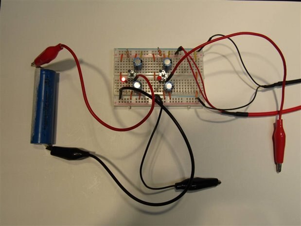
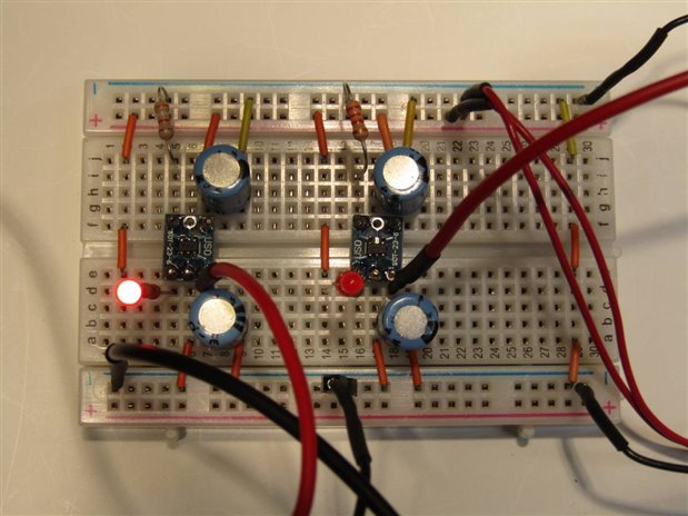
I am testing out a cordless screw driver. When I first plugged it into the charger a red LED light was suppose to light but it didn't. After a couple hours I opened the unit up and checked for circuit problems,


image

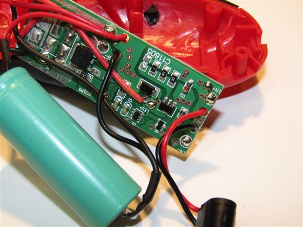
The SOT89 in the center right of the circuit board is a B772 NPN transistor and it controls the charge current. Below it, the small transistor is a 2N7002 ( an N Ch MOSFET) and it is the driver that controls the B772. The U1 which I haven't IDed is probably the charge controller. When I first opened the unit I had 5 volts on the emitter of the B772 and no volts on the Collector. The Li-ion battery was sitting at 0.6 volts. In the course of my testing I eventually put a small token charge into the battery and at this point the unit started charging as normal.


My question is this: Did the extremely low charge level of the battery cause the charge circuit to default to a no charge situation or is there likely a secondary fault in the circuit that has just decided to temporarily heal itself? Any insights would be appreciated. I have minimal experience with this type of charging circuit.


John

  • Sign in to reply
  • Cancel

Top Replies

  • genebren
    genebren over 7 years ago +9 verified
    John, I am working on a Li-ion battery charger right now (and I have developed others in the past). Most of the Li-ion chargers have a 'battery check' (injecting a small current into the battery and looking…
  • mcb1
    mcb1 over 7 years ago +8 suggested
    You should know by now that anything that is broken, always works when you take it to get fixed ... It wouldn't surprise me if the low voltage caused the charging to shut down. Lithium Ion cells shouldn…
  • jw0752
    jw0752 over 7 years ago in reply to genebren +7
    Hi Gene, that is exactly the info I was looking for. There was some crystallized spillage on the circuit board which would have provided a discharge path for the battery while it was still liquid. It looked…
Parents
  • genebren
    0 genebren over 7 years ago

    John,


    I am working on a Li-ion battery charger right now (and I have developed others in the past).  Most of the Li-ion chargers have a 'battery check' (injecting a small current into the battery and looking for the voltage at the battery terminal to stay below the charge termination voltage, i.e 4.2V) process that must pass before the device goes into the charging mode.  The next step is usually a preconditioning phase, where again a low current (% of normal charge current) is applied to the battery until the battery voltage rises to the proper level at which point the battery enters a constant current charge.


    The charger chip that I am using is a Microchip MCP73831/2.  This chip turns on the 'charging' LED as soon as the device enters either the preconditioning or charging stage.  Not all devices have the same logic, but if my charger failed the 'battery check' the device would sit with the LED off.


    Having used other charging chips, I have seen a fair number of chargers fail to charge batteries.  One of the reoccurring failure that I have seen has been due to a high impedance path (connectors, switches, wires, etc.) on the charger input voltage.  As the charger enters 'charging', the current rises quickly and the 'high input impedance' causes a large voltage drop, causing the charger to shutdown due to insufficient voltage.  What happens is the charger chip begins to oscillate and the charger never delivers charge to the battery (sometimes actually further draining the battery).


    As pointed out by mcb1, operating/allowing Li-ion batteries to drop to this low of a voltage is very bad for the life/performance of the cell.  Keep an eye on this drill and/or replace the battery or return it as damaged to the vendor.


    Good luck,

    Gene

    • Cancel
    • Vote Up +9 Vote Down
    • Sign in to reply
    • Verify Answer
    • Reject Answer
    • Cancel
Reply
  • genebren
    0 genebren over 7 years ago

    John,


    I am working on a Li-ion battery charger right now (and I have developed others in the past).  Most of the Li-ion chargers have a 'battery check' (injecting a small current into the battery and looking for the voltage at the battery terminal to stay below the charge termination voltage, i.e 4.2V) process that must pass before the device goes into the charging mode.  The next step is usually a preconditioning phase, where again a low current (% of normal charge current) is applied to the battery until the battery voltage rises to the proper level at which point the battery enters a constant current charge.


    The charger chip that I am using is a Microchip MCP73831/2.  This chip turns on the 'charging' LED as soon as the device enters either the preconditioning or charging stage.  Not all devices have the same logic, but if my charger failed the 'battery check' the device would sit with the LED off.


    Having used other charging chips, I have seen a fair number of chargers fail to charge batteries.  One of the reoccurring failure that I have seen has been due to a high impedance path (connectors, switches, wires, etc.) on the charger input voltage.  As the charger enters 'charging', the current rises quickly and the 'high input impedance' causes a large voltage drop, causing the charger to shutdown due to insufficient voltage.  What happens is the charger chip begins to oscillate and the charger never delivers charge to the battery (sometimes actually further draining the battery).


    As pointed out by mcb1, operating/allowing Li-ion batteries to drop to this low of a voltage is very bad for the life/performance of the cell.  Keep an eye on this drill and/or replace the battery or return it as damaged to the vendor.


    Good luck,

    Gene

    • Cancel
    • Vote Up +9 Vote Down
    • Sign in to reply
    • Verify Answer
    • Reject Answer
    • Cancel
Children
  • jw0752
    0 jw0752 over 7 years ago in reply to genebren

    Hi Gene, that is exactly the info I was looking for. There was some crystallized spillage on the circuit board which would have provided a discharge path for the battery while it was still liquid. It looked like capacitor electrolyte but there was no capacitor in the circuit to have leaked. In any case the very low voltage condition of the battery was a concern I just didn't know if it would cause the charge to  fail to start. I will attempt to read the number of the control chip when I get a chance. Thanks Again.

    John

    • Cancel
    • Vote Up +7 Vote Down
    • Sign in to reply
    • Verify Answer
    • Cancel
  • jw0752
    0 jw0752 over 7 years ago in reply to genebren

    Hi Gene,

    Thanks again for your suggestion to check out the MCP73831-2. I have ordered a few so I can experiment.

    John

    • Cancel
    • Vote Up +2 Vote Down
    • Sign in to reply
    • Verify Answer
    • Reject Answer
    • Cancel
  • jw0752
    0 jw0752 over 7 years ago in reply to genebren

    Hi genebren  ,


    Your recommendation of the MCP 73831/2 Li-ion charge management chip is very appreciated. I have finally received some of these chips and I have begun to experiment with them. Since they are SMD I mounted them to adapter boards so that I could use them on the bread board as DIP 6. Here is the bread board with two individual chargers set up.


    imageimage


    I used the typical application schematic from the data sheet to wire the circuits. This chip is very user friendly. It is programmable so that the Max charging current can be controlled by changing a resistor between the Prog pin and ground. The optimal charging current is between 1/2 and 1 C. By using a 2.2K resistor as the program resistor the constant current during that phase of the charging is 450 mA. I experimented with other values and settled on using a 3.9 K resistor as my little adapter boards did not provide much of a heat sink for the chip.


    image

    The chip is thermally controlled so that the chip will self protect to a lower current if the junction temperature gets above 150C. Because of this protection my chip was running at 250 mA even though I had it programmed for 500 mA. By changing the program resistor to 3.9K I just brought the charge level back to a point where the junction temp stayed below 150C. The program resistor can also be used as an enable/ disable to the charger. If the resistor is left floating the circuit shuts down. This would enable interfacing with a micro controller.


    The chip has many conditions that it checks and then decides how best to charge the battery. If the battery is very low it initiates with a precharge protocol to get things started and then transitions to constant current. The point when it transitions to constant current is when there is the most heat stress on the chip. The supply voltage Vin is typically between 4.5 and 6 volts. With the battery at a low voltage level and the current at the program limit there may be as much as a 3 volt drop at 500 mA across the chip at this point. This is a lot of wattage to shed from a small SOT23-5 package. By automatically lowering the charge current as needed to control the heat the chip charges the battery and as the voltage of the battery increases the heat problem ameliorates. When the voltage of the battery approaches the terminal voltage the chip switches to a constant voltage phase and eventually shuts down when 4.2 volts is reached. The chip has versions available for 3 different terminal voltages. The final digit on my chips "2" designates them as 4.2 volt chips. The chip also has a status pin that will turn an LED on or off to give a general indication whether the chip is in standby or charge modes.


    I want to thank you for the fun I had exploring this neat little charging tool.


    The great benefit for me in the forum is the inspiration and guidance that I receive from interacting with everyone here.


    John

    • Cancel
    • Vote Up +5 Vote Down
    • Sign in to reply
    • Verify Answer
    • Reject Answer
    • Cancel
  • genebren
    0 genebren over 7 years ago in reply to jw0752

    John,


    Great job on the charger and an excellent description of its functionality and operation.  The specification sheet for the device does a good job of describing the operation, but it also obscures some very valuable information.


    The PROG pin - current programming and floating the pin to disable the device.  Yes, but a more useful fact that the specification does not highlight well is that you can also drive this pin to VCC to disable it.  This is a bit more microprocessor friendly, as you can tri-state a connected GPIO and then switch it on and drive it high to disable it (i.e you do not need to psychically remove the programming resistor to disable) .  Also, you can monitor the voltage on this pin to determine the actual charging current.  A reading of 1.0V represents 100% of the programmed current value and a reading of 0.0 would represent 0% (although the device never really drive below 5%.


    Glad you had a little fun with this chip.


    Gene

    • Cancel
    • Vote Up +3 Vote Down
    • Sign in to reply
    • Verify Answer
    • Reject Answer
    • Cancel
  • jw0752
    0 jw0752 over 7 years ago in reply to genebren

    Hi Gene,

    You are correct those are good things to know. I did not like the idea of disconnecting the resistor as this did not feel very elegant. Much better to drive the resistor closer to Vcc. A quarter watt 2 K resistor will be able to handle 5 volts easily and any program resistor greater than 2 K will have even less wattage to dissipate. I also like the idea that the charge current can be monitored by measuring the voltage on the program pin. This is much less invasive that using an ammeter.


    Thanks John

    • Cancel
    • Vote Up +1 Vote Down
    • Sign in to reply
    • Verify Answer
    • Reject Answer
    • Cancel
  • jw0752
    0 jw0752 over 7 years ago in reply to genebren

    Hi Gene,


    Can you clarify the voltage on prog correspondence with current. Since the current of the output goes up as the resistance between prog and ground decreases it would seem that 0 volts would be 100% and Vcc would be 0%.


    John

    • Cancel
    • Vote Up +1 Vote Down
    • Sign in to reply
    • Verify Answer
    • Cancel
  • genebren
    0 genebren over 7 years ago in reply to jw0752

    John,


    The programming resistor sets the maximum current value (2K = 500mA).  In normal operation, when the charger is applying the maximum current, the voltage on the PROG pin will read 1.0V.  If the charger is limiting the current to 250mA, or 50% of the maximum value, the voltage on the PROG pin will read 0.5V.


    The same is true for your case, with a resistor of 2.2K (450mA max), a reading of 1.0V on PROG means the the current is 450mA, while a reading of 0.5 means that the current is 225mA (or 50% of maximum).


    So what ever the programmed maximum current, the voltage on PROG gives you the relative current.


    Gene

    • Cancel
    • Vote Up +4 Vote Down
    • Sign in to reply
    • Verify Answer
    • Reject Answer
    • Cancel
  • jw0752
    0 jw0752 over 7 years ago in reply to genebren

    That makes more sense. And if the pin has voltage applied taking it close to Vcc the circuit shuts down while letting it float using a tristate output will restore it to normal operation. Got it!

    John

    • Cancel
    • Vote Up +2 Vote Down
    • Sign in to reply
    • Verify Answer
    • Cancel
element14 Community

element14 is the first online community specifically for engineers. Connect with your peers and get expert answers to your questions.

  • Members
  • Learn
  • Technologies
  • Challenges & Projects
  • Products
  • Store
  • About Us
  • Feedback & Support
  • FAQs
  • Terms of Use
  • Privacy Policy
  • Legal and Copyright Notices
  • Sitemap
  • Cookies

An Avnet Company © 2025 Premier Farnell Limited. All Rights Reserved.

Premier Farnell Ltd, registered in England and Wales (no 00876412), registered office: Farnell House, Forge Lane, Leeds LS12 2NE.

ICP 备案号 10220084.

Follow element14

  • X
  • Facebook
  • linkedin
  • YouTube