element14 Community
element14 Community
    Register Log In
  • Site
  • Search
  • Log In Register
  • About Us
  • Community Hub
    Community Hub
    • What's New on element14
    • Feedback and Support
    • Benefits of Membership
    • Personal Blogs
    • Members Area
    • Achievement Levels
  • Learn
    Learn
    • Ask an Expert
    • eBooks
    • element14 presents
    • Learning Center
    • Tech Spotlight
    • STEM Academy
    • Webinars, Training and Events
    • Learning Groups
  • Technologies
    Technologies
    • 3D Printing
    • FPGA
    • Industrial Automation
    • Internet of Things
    • Power & Energy
    • Sensors
    • Technology Groups
  • Challenges & Projects
    Challenges & Projects
    • Design Challenges
    • element14 presents Projects
    • Project14
    • Arduino Projects
    • Raspberry Pi Projects
    • Project Groups
  • Products
    Products
    • Arduino
    • Avnet Boards Community
    • Dev Tools
    • Manufacturers
    • Multicomp Pro
    • Product Groups
    • Raspberry Pi
    • RoadTests & Reviews
  • Store
    Store
    • Visit Your Store
    • Choose another store...
      • Europe
      •  Austria (German)
      •  Belgium (Dutch, French)
      •  Bulgaria (Bulgarian)
      •  Czech Republic (Czech)
      •  Denmark (Danish)
      •  Estonia (Estonian)
      •  Finland (Finnish)
      •  France (French)
      •  Germany (German)
      •  Hungary (Hungarian)
      •  Ireland
      •  Israel
      •  Italy (Italian)
      •  Latvia (Latvian)
      •  
      •  Lithuania (Lithuanian)
      •  Netherlands (Dutch)
      •  Norway (Norwegian)
      •  Poland (Polish)
      •  Portugal (Portuguese)
      •  Romania (Romanian)
      •  Russia (Russian)
      •  Slovakia (Slovak)
      •  Slovenia (Slovenian)
      •  Spain (Spanish)
      •  Sweden (Swedish)
      •  Switzerland(German, French)
      •  Turkey (Turkish)
      •  United Kingdom
      • Asia Pacific
      •  Australia
      •  China
      •  Hong Kong
      •  India
      •  Korea (Korean)
      •  Malaysia
      •  New Zealand
      •  Philippines
      •  Singapore
      •  Taiwan
      •  Thailand (Thai)
      • Americas
      •  Brazil (Portuguese)
      •  Canada
      •  Mexico (Spanish)
      •  United States
      Can't find the country/region you're looking for? Visit our export site or find a local distributor.
  • Translate
  • Profile
  • Settings
Test & Tools
  • Technologies
  • More
Test & Tools
Forum Connection options for copper pour
  • Blog
  • Forum
  • Documents
  • Files
  • Members
  • Mentions
  • Sub-Groups
  • Tags
  • More
  • Cancel
  • New
Join Test & Tools to participate - click to join for free!
Actions
  • Share
  • More
  • Cancel
Forum Thread Details
  • State Verified Answer
  • Replies 3 replies
  • Answers 1 answer
  • Subscribers 356 subscribers
  • Views 711 views
  • Users 0 members are here
  • pcb
  • copper pour
  • current amplifier
Related

Connection options for copper pour

three-phase
three-phase over 6 years ago

Hello,


I am building up a little current amplifier to allow me to test the frequency response of some Rogowski coils that I want to adapt for use with a transient analyser.


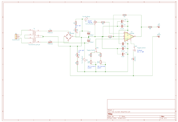
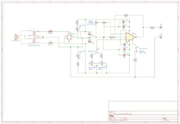
The amplifier will be driven from a waveform generator and have a selectable 1A / 2A current limit on the output. This will drive a current clamp table I will build to give the higher currents for the Rogowski coils.


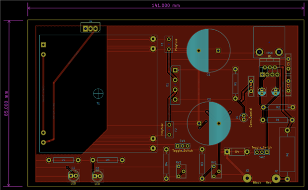
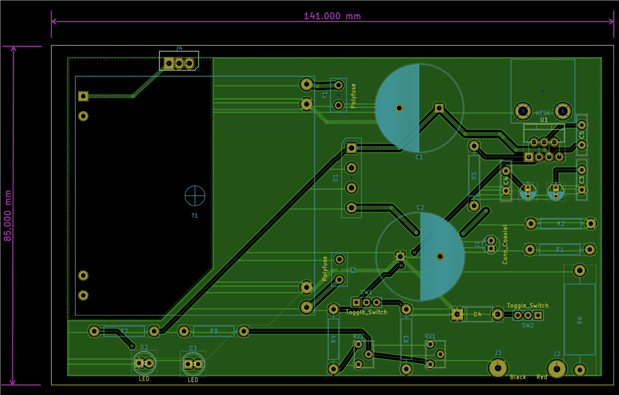
The PCB houses a simple dual rail power supply to provide power to the OP-amp, that I have created a large exclusion zone around the mains connections and tracks.


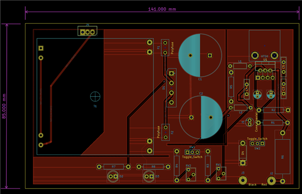
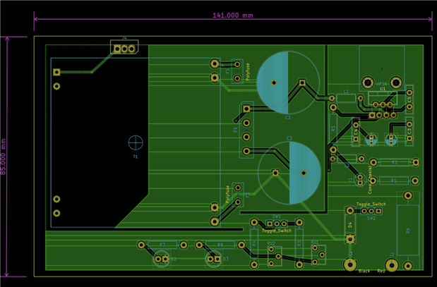
Below is the schematic, and the front and back copper layouts.


image


image


image


Two questions spring to mind.


1) The copper pour has been connected to the centre (0V) rail of the rectifier D1. Is this the best connection for it?


2) PCB tracks for mains, DC supply rails and amplifier output and 1.0mm wide tracks. Is this adequate enough?


Kind regards.

  • Sign in to reply
  • Cancel

Top Replies

  • shabaz
    shabaz over 6 years ago +1 verified
    Hi Donald, Interesting project! I think it's fine, although generally there is separation between the amplifier circuit, and the PSU, i.e. two separate ground planes, connected at one point. And as unbroken…
  • three-phase
    three-phase over 6 years ago in reply to shabaz +1
    Many thanks Shabaz, The PCB track calculator is very useful, a link worth saving. I will have a look to see if I can produce two ground planes. I may be able to join them at the corner of the transformer…
  • three-phase
    three-phase over 6 years ago in reply to shabaz +1 suggested
    Hello Shabaz, I have carried out some more work on the PCB. As long as I have understood what you have meant..... Ferrite beads have been added into each supply rail and I have juggled the components about…
Parents
  • shabaz
    0 shabaz over 6 years ago

    Hi Donald,


    Interesting project!

    I think it's fine, although generally there is separation between the amplifier circuit, and the PSU, i.e. two separate ground planes, connected at one point. And as unbroken as possible (harder on a 2-layer board). A ferrite bead between the PSU and the amplifier circuit is useful too, not just to provide some high frequency filtering, but also so that if desoldered, the two circuits are isolated for testing. C6 and and C8 may need to be higher value than 10uF for good decoupling, so it could be worth leaving a slightly bigger space for them on the PCB.

    Regarding track widths, generally I'll default to 8mil or 6mil for signals, and thicker (e.g. 16 or 24 or higher) otherwise. There's some standards for that, also some online PCB calculators, e.g. this one: https://www.4pcb.com/trace-width-calculator.html

    • Cancel
    • Vote Up +1 Vote Down
    • Sign in to reply
    • Verify Answer
    • Reject Answer
    • Cancel
Reply
  • shabaz
    0 shabaz over 6 years ago

    Hi Donald,


    Interesting project!

    I think it's fine, although generally there is separation between the amplifier circuit, and the PSU, i.e. two separate ground planes, connected at one point. And as unbroken as possible (harder on a 2-layer board). A ferrite bead between the PSU and the amplifier circuit is useful too, not just to provide some high frequency filtering, but also so that if desoldered, the two circuits are isolated for testing. C6 and and C8 may need to be higher value than 10uF for good decoupling, so it could be worth leaving a slightly bigger space for them on the PCB.

    Regarding track widths, generally I'll default to 8mil or 6mil for signals, and thicker (e.g. 16 or 24 or higher) otherwise. There's some standards for that, also some online PCB calculators, e.g. this one: https://www.4pcb.com/trace-width-calculator.html

    • Cancel
    • Vote Up +1 Vote Down
    • Sign in to reply
    • Verify Answer
    • Reject Answer
    • Cancel
Children
  • three-phase
    0 three-phase over 6 years ago in reply to shabaz

    Many thanks Shabaz,


    The PCB track calculator is very useful, a link worth saving.


    I will have a look to see if I can produce two ground planes. I may be able to join them at the corner of the transformer somewhere near R4, although the track through to R7 may become an issue. I think there is plenty of room to move the components around to split up the ground planes.


    I will then look to see what ferrite beads would be available to me, I presume I would need on in each rail of the supply? The sizes for capacitors C6 and C8 came from the data sheet for the amplifier. I will also only look to go up to 30kHz with this as well as that is the maximum bandwidth of the transient analyser.


    Kind regards.

    • Cancel
    • Vote Up +1 Vote Down
    • Sign in to reply
    • Verify Answer
    • Cancel
  • three-phase
    0 three-phase over 6 years ago in reply to shabaz

    Hello Shabaz,


    I have carried out some more work on the PCB. As long as I have understood what you have meant.....


    Ferrite beads have been added into each supply rail and I have juggled the components about to allow the ground planes to be split with just one connection between them. Not sure about what size that connection should have been, so I went with the electrical approach. image


    image

    image

    image


    Kind regards.

    • Cancel
    • Vote Up +1 Vote Down
    • Sign in to reply
    • Verify Answer
    • Reject Answer
    • Cancel
element14 Community

element14 is the first online community specifically for engineers. Connect with your peers and get expert answers to your questions.

  • Members
  • Learn
  • Technologies
  • Challenges & Projects
  • Products
  • Store
  • About Us
  • Feedback & Support
  • FAQs
  • Terms of Use
  • Privacy Policy
  • Legal and Copyright Notices
  • Sitemap
  • Cookies

An Avnet Company © 2025 Premier Farnell Limited. All Rights Reserved.

Premier Farnell Ltd, registered in England and Wales (no 00876412), registered office: Farnell House, Forge Lane, Leeds LS12 2NE.

ICP 备案号 10220084.

Follow element14

  • X
  • Facebook
  • linkedin
  • YouTube