Hello,
I am building up a little current amplifier to allow me to test the frequency response of some Rogowski coils that I want to adapt for use with a transient analyser.
The amplifier will be driven from a waveform generator and have a selectable 1A / 2A current limit on the output. This will drive a current clamp table I will build to give the higher currents for the Rogowski coils.
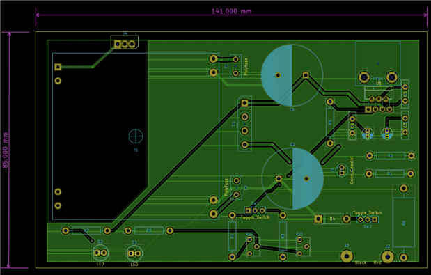
The PCB houses a simple dual rail power supply to provide power to the OP-amp, that I have created a large exclusion zone around the mains connections and tracks.
Below is the schematic, and the front and back copper layouts.
Two questions spring to mind.
1) The copper pour has been connected to the centre (0V) rail of the rectifier D1. Is this the best connection for it?
2) PCB tracks for mains, DC supply rails and amplifier output and 1.0mm wide tracks. Is this adequate enough?
Kind regards.


