element14 Community
element14 Community
    Register Log In
  • Site
  • Search
  • Log In Register
  • About Us
  • Community Hub
    Community Hub
    • What's New on element14
    • Feedback and Support
    • Benefits of Membership
    • Personal Blogs
    • Members Area
    • Achievement Levels
  • Learn
    Learn
    • Ask an Expert
    • eBooks
    • element14 presents
    • Learning Center
    • Tech Spotlight
    • STEM Academy
    • Webinars, Training and Events
    • Learning Groups
  • Technologies
    Technologies
    • 3D Printing
    • FPGA
    • Industrial Automation
    • Internet of Things
    • Power & Energy
    • Sensors
    • Technology Groups
  • Challenges & Projects
    Challenges & Projects
    • Design Challenges
    • element14 presents Projects
    • Project14
    • Arduino Projects
    • Raspberry Pi Projects
    • Project Groups
  • Products
    Products
    • Arduino
    • Avnet Boards Community
    • Dev Tools
    • Manufacturers
    • Multicomp Pro
    • Product Groups
    • Raspberry Pi
    • RoadTests & Reviews
  • Store
    Store
    • Visit Your Store
    • Choose another store...
      • Europe
      •  Austria (German)
      •  Belgium (Dutch, French)
      •  Bulgaria (Bulgarian)
      •  Czech Republic (Czech)
      •  Denmark (Danish)
      •  Estonia (Estonian)
      •  Finland (Finnish)
      •  France (French)
      •  Germany (German)
      •  Hungary (Hungarian)
      •  Ireland
      •  Israel
      •  Italy (Italian)
      •  Latvia (Latvian)
      •  
      •  Lithuania (Lithuanian)
      •  Netherlands (Dutch)
      •  Norway (Norwegian)
      •  Poland (Polish)
      •  Portugal (Portuguese)
      •  Romania (Romanian)
      •  Russia (Russian)
      •  Slovakia (Slovak)
      •  Slovenia (Slovenian)
      •  Spain (Spanish)
      •  Sweden (Swedish)
      •  Switzerland(German, French)
      •  Turkey (Turkish)
      •  United Kingdom
      • Asia Pacific
      •  Australia
      •  China
      •  Hong Kong
      •  India
      •  Korea (Korean)
      •  Malaysia
      •  New Zealand
      •  Philippines
      •  Singapore
      •  Taiwan
      •  Thailand (Thai)
      • Americas
      •  Brazil (Portuguese)
      •  Canada
      •  Mexico (Spanish)
      •  United States
      Can't find the country/region you're looking for? Visit our export site or find a local distributor.
  • Translate
  • Profile
  • Settings
Test & Tools
  • Technologies
  • More
Test & Tools
Forum Impact of scope noise when measuring signals
  • Blog
  • Forum
  • Documents
  • Files
  • Members
  • Mentions
  • Sub-Groups
  • Tags
  • More
  • Cancel
  • New
Join Test & Tools to participate - click to join for free!
Actions
  • Share
  • More
  • Cancel
Forum Thread Details
  • State Verified Answer
  • Replies 29 replies
  • Answers 8 answers
  • Subscribers 356 subscribers
  • Views 8888 views
  • Users 0 members are here
Related

Impact of scope noise when measuring signals

Andrew J
Andrew J over 4 years ago

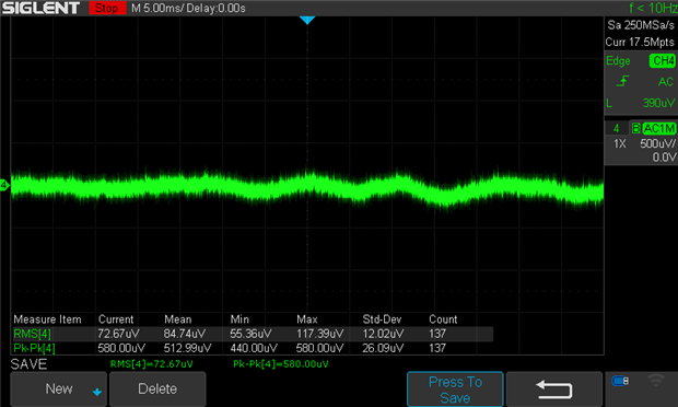
I'm currently taking noise measurements of a working circuit and I don't really understand how my scope's noise actually impacts what I see or measure so I'm hoping someone can explain it to me in non-technical (or at least not deep technical!) language.  I've measured the scope's noise floor(??) on channel 4:


image

Image 1: no connections


Scope has no probes connected, is set to maximise capture memory and is at the smallest V div possible.  I've shown RMS and pk-pk measurements (I believe RMS is more relevant to noise, is that right?)


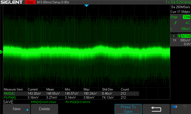
Here I'm taking a signal measurement on channel 4, with the probe set at x1 using a pig-tail and the scope configured as: AC coupled, 20MHz bandwidth, peak detect acquisition, no other probes connected or channels turned on, measurements reset to zero first:


image

Image 2: measured signal (core signal is 0.37mV pk-pk)


What I'm interested in understanding:

  1. How does the scope noise measured when the channel is disconnected from a probe - noise floor? - impact on the measured signal?
  2. How do I take that into account when interpreting the signal?  For example, could I take the mean RMS value shown in image 1, from the mean RMS value in image 2?  Does it mean the scope just isn't capable of measuring signals around the min-max RMS values?
  3. I don't touch the probe once I've started taking measurements - it's connected on test points - but even a fractional movement can change the measured signal to the extent I can't trust that I've made a proper probe connection, if that makes sense.  Specifically, the amplitude of the 'spikes' can grow or shrink although the 'core' signal remains pretty much as-is; by 'core' I mean the bright green portion of what is shown.  Does that imply anything about the spikes not related to my circuit - environment noise?  Probing issue?
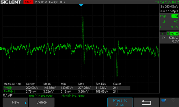
    I've turned off other devices and lights in the room with no impact.  I get the same signal measuring directly across an output cap (albeit a 10uF electrolytic.)  I've zoomed in to the signal in the image below - although regular, it doesn't look like switching noise:


image

Image 3: measured signal in image 2 zoomed in.


Please correct me where I've mistyped anything in the above - it helps me make sure I research the right thing and not the thing I think is right!! 

  • Sign in to reply
  • Cancel

Top Replies

  • Gough Lui
    Gough Lui over 4 years ago +6 verified
    Can't say I'm an expert, but here goes at my understanding: How does the scope noise measured when the channel is disconnected from a probe - noise floor? - impact on the measured signal? How do I take…
  • shabaz
    shabaz over 4 years ago in reply to Andrew J +3 suggested
    Hi Andrew, The 'scope noise can be higher than the power supply you're measuring, so on it's own the 'scope isn't going to provide the measurement you need I think. Regarding your question 1, you'll see…
  • DAB
    DAB over 4 years ago +2 suggested
    You raise some good issues. Without a probe attached you are getting noise through the input connectors. first thing to do is at least put a terminating load on the input so you are not picking up noise…
Parents
  • Jan Cumps
    0 Jan Cumps over 4 years ago

    The ferrites will likely not help when placed between supply entry and your circuit. It looks like noise either generated by or picked up by your circuit.

    Because you put it in a tin can, it almost looks like self-generated...

    • Cancel
    • Vote Up +1 Vote Down
    • Sign in to reply
    • Verify Answer
    • Cancel
  • Andrew J
    0 Andrew J over 4 years ago in reply to Jan Cumps

    I think it is self-generated and there is, actually, a few 10's of uV being picked up from my overhead LED desk lamp.  I'm way out of my knowledge depth on this but my thoughts turn to noise on the ground plane; noise from regulators/inductors/capacitors etc.  Attaching a second scope probe into the circuit will reduce the spikes seen in Image 2 (or the third image in the post just above this) by 50%.  Interesting though, but I wish it was easier to research image

    • Cancel
    • Vote Up 0 Vote Down
    • Sign in to reply
    • Verify Answer
    • Cancel
  • Jan Cumps
    0 Jan Cumps over 4 years ago in reply to Andrew J

    The second probe adds some pF - usually documented for 10x.


    I have Tek probes that state < 12 pF (a sticker on the coax connector)

    Rigol: 15 +- 5 pF (leaflet)

    Velleman: 20 pF

    No-brand: 20 pF

    Mueller probe (really !): 18 pF

    • Cancel
    • Vote Up 0 Vote Down
    • Sign in to reply
    • Verify Answer
    • Cancel
  • Andrew J
    0 Andrew J over 4 years ago in reply to Jan Cumps

    Yes - I naively thought that adding some capacitance at the same place would show me a similar impact.  The Siglent probes I use have an input capacitance of 85pF - 120pF at x1 and 18.5pF - 22.5pF at x10. 

    • Cancel
    • Vote Up 0 Vote Down
    • Sign in to reply
    • Verify Answer
    • Cancel
Reply
  • Andrew J
    0 Andrew J over 4 years ago in reply to Jan Cumps

    Yes - I naively thought that adding some capacitance at the same place would show me a similar impact.  The Siglent probes I use have an input capacitance of 85pF - 120pF at x1 and 18.5pF - 22.5pF at x10. 

    • Cancel
    • Vote Up 0 Vote Down
    • Sign in to reply
    • Verify Answer
    • Cancel
Children
  • Jan Cumps
    0 Jan Cumps over 4 years ago in reply to Andrew J

    I would not use the x1 position - unless there's a compelling reason.

    Less bandwidth, more capacity, more loading on the circuit.

    • Cancel
    • Vote Up 0 Vote Down
    • Sign in to reply
    • Verify Answer
    • Cancel
  • Andrew J
    0 Andrew J over 4 years ago in reply to Jan Cumps

    I'm measuring the noise on the signal and a x10 is going to show a lot higher noise than at x1 because of the attenuation.  Yes, the x1 loads the DUT more and cuts the bandwidth down from 100MHz to, what I don't know, as the Siglent data sheet isn't that great for its probes but let's take a guess at < 10 MHz.  Under general measurement I tend to do that at x10.

    • Cancel
    • Vote Up 0 Vote Down
    • Sign in to reply
    • Verify Answer
    • Cancel
  • Jan Cumps
    0 Jan Cumps over 4 years ago in reply to Andrew J

    Because I'm a fan and because they are very good videos:


    You don't have permission to edit metadata of this video.
    Edit media
    x
    image
    Upload Preview
    image


    You don't have permission to edit metadata of this video.
    Edit media
    x
    image
    Upload Preview
    image

    • Cancel
    • Vote Up +1 Vote Down
    • Sign in to reply
    • Verify Answer
    • Reject Answer
    • Cancel
element14 Community

element14 is the first online community specifically for engineers. Connect with your peers and get expert answers to your questions.

  • Members
  • Learn
  • Technologies
  • Challenges & Projects
  • Products
  • Store
  • About Us
  • Feedback & Support
  • FAQs
  • Terms of Use
  • Privacy Policy
  • Legal and Copyright Notices
  • Sitemap
  • Cookies

An Avnet Company © 2025 Premier Farnell Limited. All Rights Reserved.

Premier Farnell Ltd, registered in England and Wales (no 00876412), registered office: Farnell House, Forge Lane, Leeds LS12 2NE.

ICP 备案号 10220084.

Follow element14

  • X
  • Facebook
  • linkedin
  • YouTube