I'm currently taking noise measurements of a working circuit and I don't really understand how my scope's noise actually impacts what I see or measure so I'm hoping someone can explain it to me in non-technical (or at least not deep technical!) language. I've measured the scope's noise floor(??) on channel 4:
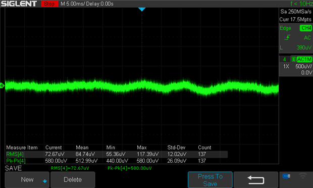
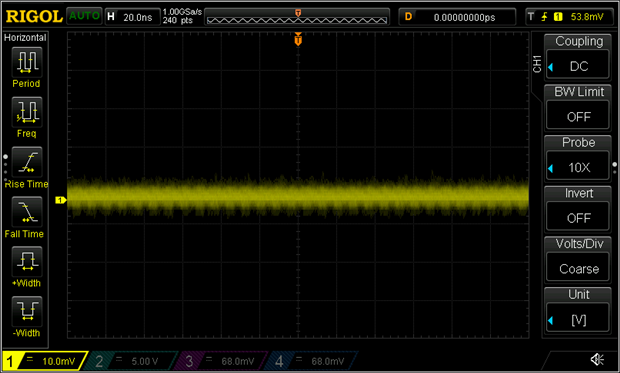
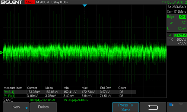
Image 1: no connections
Scope has no probes connected, is set to maximise capture memory and is at the smallest V div possible. I've shown RMS and pk-pk measurements (I believe RMS is more relevant to noise, is that right?)
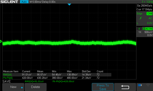
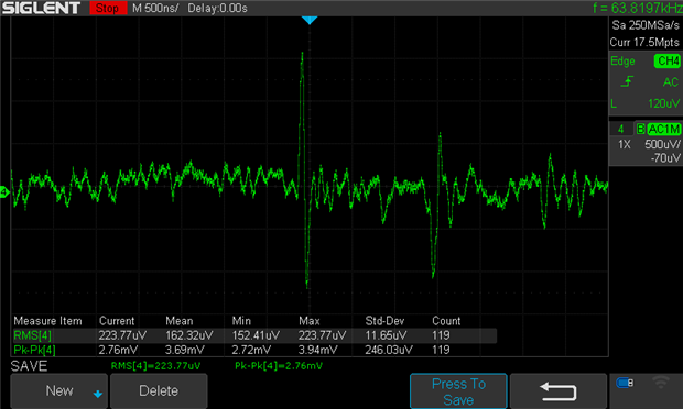
Here I'm taking a signal measurement on channel 4, with the probe set at x1 using a pig-tail and the scope configured as: AC coupled, 20MHz bandwidth, peak detect acquisition, no other probes connected or channels turned on, measurements reset to zero first:
Image 2: measured signal (core signal is 0.37mV pk-pk)
What I'm interested in understanding:
- How does the scope noise measured when the channel is disconnected from a probe - noise floor? - impact on the measured signal?
- How do I take that into account when interpreting the signal? For example, could I take the mean RMS value shown in image 1, from the mean RMS value in image 2? Does it mean the scope just isn't capable of measuring signals around the min-max RMS values?
- I don't touch the probe once I've started taking measurements - it's connected on test points - but even a fractional movement can change the measured signal to the extent I can't trust that I've made a proper probe connection, if that makes sense. Specifically, the amplitude of the 'spikes' can grow or shrink although the 'core' signal remains pretty much as-is; by 'core' I mean the bright green portion of what is shown. Does that imply anything about the spikes not related to my circuit - environment noise? Probing issue?
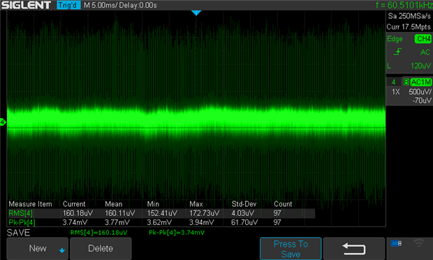
I've turned off other devices and lights in the room with no impact. I get the same signal measuring directly across an output cap (albeit a 10uF electrolytic.) I've zoomed in to the signal in the image below - although regular, it doesn't look like switching noise:
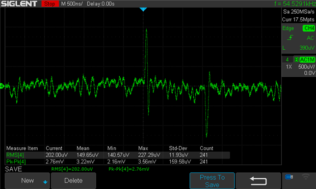
Image 3: measured signal in image 2 zoomed in.
Please correct me where I've mistyped anything in the above - it helps me make sure I research the right thing and not the thing I think is right!!