element14 Community
element14 Community
    Register Log In
  • Site
  • Search
  • Log In Register
  • Community Hub
    Community Hub
    • What's New on element14
    • Feedback and Support
    • Benefits of Membership
    • Personal Blogs
    • Members Area
    • Achievement Levels
  • Learn
    Learn
    • Ask an Expert
    • eBooks
    • element14 presents
    • Learning Center
    • Tech Spotlight
    • STEM Academy
    • Webinars, Training and Events
    • Learning Groups
  • Technologies
    Technologies
    • 3D Printing
    • FPGA
    • Industrial Automation
    • Internet of Things
    • Power & Energy
    • Sensors
    • Technology Groups
  • Challenges & Projects
    Challenges & Projects
    • Design Challenges
    • element14 presents Projects
    • Project14
    • Arduino Projects
    • Raspberry Pi Projects
    • Project Groups
  • Products
    Products
    • Arduino
    • Avnet & Tria Boards Community
    • Dev Tools
    • Manufacturers
    • Multicomp Pro
    • Product Groups
    • Raspberry Pi
    • RoadTests & Reviews
  • About Us
  • Store
    Store
    • Visit Your Store
    • Choose another store...
      • Europe
      •  Austria (German)
      •  Belgium (Dutch, French)
      •  Bulgaria (Bulgarian)
      •  Czech Republic (Czech)
      •  Denmark (Danish)
      •  Estonia (Estonian)
      •  Finland (Finnish)
      •  France (French)
      •  Germany (German)
      •  Hungary (Hungarian)
      •  Ireland
      •  Israel
      •  Italy (Italian)
      •  Latvia (Latvian)
      •  
      •  Lithuania (Lithuanian)
      •  Netherlands (Dutch)
      •  Norway (Norwegian)
      •  Poland (Polish)
      •  Portugal (Portuguese)
      •  Romania (Romanian)
      •  Russia (Russian)
      •  Slovakia (Slovak)
      •  Slovenia (Slovenian)
      •  Spain (Spanish)
      •  Sweden (Swedish)
      •  Switzerland(German, French)
      •  Turkey (Turkish)
      •  United Kingdom
      • Asia Pacific
      •  Australia
      •  China
      •  Hong Kong
      •  India
      •  Korea (Korean)
      •  Malaysia
      •  New Zealand
      •  Philippines
      •  Singapore
      •  Taiwan
      •  Thailand (Thai)
      • Americas
      •  Brazil (Portuguese)
      •  Canada
      •  Mexico (Spanish)
      •  United States
      Can't find the country/region you're looking for? Visit our export site or find a local distributor.
  • Translate
  • Profile
  • Settings
Test & Tools
  • Technologies
  • More
Test & Tools
Forum Are there any adverse effects from isolating the AC power supply on my electronics bench?
  • Blog
  • Forum
  • Documents
  • Files
  • Members
  • Mentions
  • Sub-Groups
  • Tags
  • More
  • Cancel
  • New
Join Test & Tools to participate - click to join for free!
Actions
  • Share
  • More
  • Cancel
Forum Thread Details
  • State Suggested Answer
  • Replies 37 replies
  • Answers 2 answers
  • Subscribers 364 subscribers
  • Views 5070 views
  • Users 0 members are here
  • modification
  • bench
  • 120vac
  • line
  • ac
  • isolation
  • conditioner
  • supply
  • power
  • secondary
Related

Are there any adverse effects from isolating the AC power supply on my electronics bench?

4ringfan
4ringfan over 10 years ago

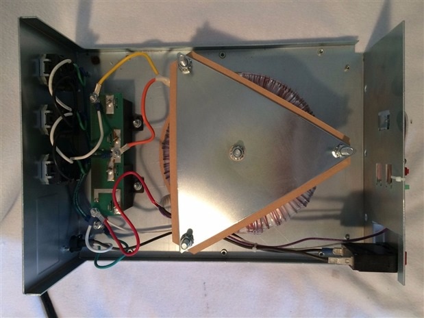
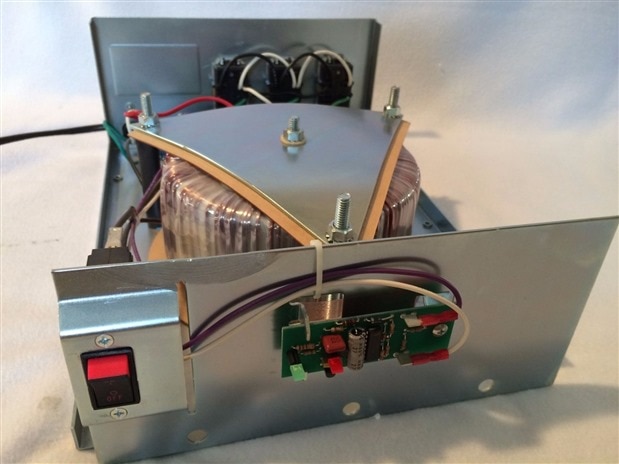
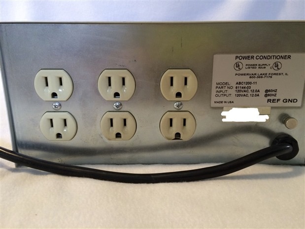
jw0752 happened to show me an Ebay listing the other day and it was like feeding candy to a baby.  My dad, he can be such an enabler!  Hehe!  So, the long and short of it is that I have acquired this BEAST (a Powervar 12 Power conditioner) and I am planning to modify it so that I can isolate and supply power to my entire bench.  The Powervac 12 is capable of supplying 12Amps at 120VAC, so the only thing I was thinking that I needed to be concerned with was possibly exceeding the supply capabilities of the transformer -- however I find the possibility of drawing that much power quite remote. So...


Here are my primary questions:


  1. Is there any reason or side effect that would contradict hooking the entire bench on the isolated secondary side of a transformer?
  2. Are there other things that I should be concerned with safety wise or otherwise plan for?
  3. Modification suggestions?
  4. In general, is this a good or bad idea?


I haven't found too many articles that talk about this, but here are links to a few that I have looked at:


isolation transformer - Electronics Forums


RadiolaGuy.com : Sonny's Tech Tips


http://www.signaltransformer.com/sites/all/pdf/IsolationTransformers%20Increase%20Safety%20of%20Electronic%20Systems.pdf


isolation - Why are we not always isolating the mains supply? - Electrical Engineering Stack Exchange


I have read the following and I take it that I should not connect any of my test equipment to the isolation, only projects that I am working on. What about power supplies?  What is the take on this?:


"DO NOT plug your test equipment into the isolation transformer, just the radio. I've seen folks wire their isolation transformer to a plug strip with all their equipment plugged into it and wonder why their "scope's" ground lead went up in smoke when they connected it to the radio chassis. If all your equipment is plugged into the isolation transformer, then nothing is "isolated"! Only the radio (or television) under test should be plugged into the isolation transformer!"


image

image

image


image


  • Sign in to reply
  • Cancel

Top Replies

  • mcb1
    mcb1 over 10 years ago in reply to 4ringfan +3 suggested
    4ringfan I'm guessing you don't want to listen to your father's advise ... I'm sure he has been able to offer some good advise. Isolating transformers are really only designed to work with double insulated…
  • mcb1
    mcb1 over 10 years ago in reply to 4ringfan +2
    4ringfan Mike Let him buy a motorcycle .. he will anyway. While we don't have the same weather problems, I brought one just after I got my licence. In those days you weren't restricted to 250cc so I brought…
  • mcb1
    mcb1 over 10 years ago in reply to peterjcs23 +2
    @peterjcs23 I'm not sure I would agree with all your conclusions. While I'm sure the corporate world may place some other restrictions, this discussion is about what those 'unseen' risks might be, and…
Parents
  • Robert Peter Oakes
    0 Robert Peter Oakes over 10 years ago

    I have not been able to keep up with this but one thing I noted (That im not sure was addressed) was that the secondary side had a ground connection through the GFCB (Ground Fault Circuit Breaker)  this would then present the same shock ability if you touched something on the secondary side of the transformer and effectively negates the need for the transformer.


    The isolation provided by the transformer is designed to allow such things as a grounded scope to be attached to a "Live wire" without frying your scope, as there is a now common ground you have not achieved this


    The ground fault protector will not work of course if there is no ground as there is no alternate route to close the circuit of the secondary side if it is not grounded


    When this is on the Mains side of the transformer it is working by measuring the difference between the two legs of the mains wires (Live and Neutral) this does not matter if in the UK or Canada, 240 or 110, we all share a common theme, the neutral is connected to ground at the transformer and sometimes also at the fuse panel, the idea behind the GFCB is that id the current is passing through the ground wire instead of the neutral back to the panel ground it will trip the breaker as the neutral line is not balanced with the live anymore


    this is the Canada / USA kind of wiring to show my point

    image

    and this is the UK version (Or one possible version) I think this also applies to Australia and parts of Europe

    imageimage


    So what is common is that for an GFCB to work it needs a path back to its source so adding an isolating transformer provides the isolation to allow you to break that return path and provide a some what level of protection to you as the unit is now isolated. But if you add a GFCB back in and ground it (Required to make it work) you loose the point of the isolating transformer unless you start constructing a "FLOATING EARTH" for the purpose of the GFCB but that's kinda defeating the point.


    This is a simplified circuit of a GFCB and as you can see, it needs the ground return to work

    image


    I think in summary, if your after personal protection, then you dont need the transformer but do need the breaker (The lower current device (5mA) would be the less painful image but either will save your life in a crunch )

    If you want to isolate equipment so you can safely probe around with your scope etc then you need an isolating transformer but you sill need to be aware that the scope or other equipment is also connected to mains ground still so you need to think about what your grounding and the possible current loops you may be setting up.


    The idea of a high power and value resistor (A MEG or more) to ground will prevent the drifting up of the isolated side but again if you connect the GFCB it negates that resistor as it will be shorting it out

    • Cancel
    • Vote Up +1 Vote Down
    • Sign in to reply
    • Verify Answer
    • Cancel
Reply
  • Robert Peter Oakes
    0 Robert Peter Oakes over 10 years ago

    I have not been able to keep up with this but one thing I noted (That im not sure was addressed) was that the secondary side had a ground connection through the GFCB (Ground Fault Circuit Breaker)  this would then present the same shock ability if you touched something on the secondary side of the transformer and effectively negates the need for the transformer.


    The isolation provided by the transformer is designed to allow such things as a grounded scope to be attached to a "Live wire" without frying your scope, as there is a now common ground you have not achieved this


    The ground fault protector will not work of course if there is no ground as there is no alternate route to close the circuit of the secondary side if it is not grounded


    When this is on the Mains side of the transformer it is working by measuring the difference between the two legs of the mains wires (Live and Neutral) this does not matter if in the UK or Canada, 240 or 110, we all share a common theme, the neutral is connected to ground at the transformer and sometimes also at the fuse panel, the idea behind the GFCB is that id the current is passing through the ground wire instead of the neutral back to the panel ground it will trip the breaker as the neutral line is not balanced with the live anymore


    this is the Canada / USA kind of wiring to show my point

    image

    and this is the UK version (Or one possible version) I think this also applies to Australia and parts of Europe

    imageimage


    So what is common is that for an GFCB to work it needs a path back to its source so adding an isolating transformer provides the isolation to allow you to break that return path and provide a some what level of protection to you as the unit is now isolated. But if you add a GFCB back in and ground it (Required to make it work) you loose the point of the isolating transformer unless you start constructing a "FLOATING EARTH" for the purpose of the GFCB but that's kinda defeating the point.


    This is a simplified circuit of a GFCB and as you can see, it needs the ground return to work

    image


    I think in summary, if your after personal protection, then you dont need the transformer but do need the breaker (The lower current device (5mA) would be the less painful image but either will save your life in a crunch )

    If you want to isolate equipment so you can safely probe around with your scope etc then you need an isolating transformer but you sill need to be aware that the scope or other equipment is also connected to mains ground still so you need to think about what your grounding and the possible current loops you may be setting up.


    The idea of a high power and value resistor (A MEG or more) to ground will prevent the drifting up of the isolated side but again if you connect the GFCB it negates that resistor as it will be shorting it out

    • Cancel
    • Vote Up +1 Vote Down
    • Sign in to reply
    • Verify Answer
    • Cancel
Children
  • mcb1
    0 mcb1 over 10 years ago in reply to Robert Peter Oakes

    the secondary side had a ground connection through the GFCB

    http://hyperphysics.phy-astr.gsu.edu/hbase/electric/gfi3.html#c1


    The ground is where the inbalance occurs, ie if the phase an neutral currents are different then it must be going to earth (or another phase as some have discovered).

    http://www.siemens.com/download?BTLV_40730


    The only ground I see is the ground wire on the load side, not the GFCB.


    Mark

    BTW we don't switch neutral on this side of the world ... that just leads to big problems.

    image

    • Cancel
    • Vote Up 0 Vote Down
    • Sign in to reply
    • Verify Answer
    • Cancel
  • Robert Peter Oakes
    0 Robert Peter Oakes over 10 years ago in reply to mcb1

    I agree but it was shown in this image which is why i mention it

    image


    also both sides of the transformer are grounded, it is  defeating the purpose of the isolating transformer, as it is a 1:1 transformer  there is still 110V or 240V AC depending on region on the output and now you can still shock yourself to ground or a grounded part of the equipment under test.


    Without the transformer being grounded, the GFCB will not work which is why I say it is not needed in a truly isolate situation. GFCB's are for personal protection and as such needs the ground to provide an alternate route back to the transformer to cause the in-balance. If there was no alternate return path, there could never be an in-balance. there could be over 1000V on the isolated side of the transformer and a person could technically hold on to either side (ONE AT A TIME) and never get a shock (I DON'T RECOMMEND TESTING THAT THEORY THOUGH AS A MISTAKE WILL BE FATAL) but if either side is grounded as in this diagram then all bets are off without the GFCB to provide a safety valve.


    I agree with you all that having two GFCB's is pointless and that one should go with the single 5mA version


    But I have yet to see how the transformer will provide protection if both sides are grounded , that's not what there used for.

    • Cancel
    • Vote Up +1 Vote Down
    • Sign in to reply
    • Verify Answer
    • Cancel
  • mcb1
    0 mcb1 over 10 years ago in reply to Robert Peter Oakes

    Peter

    Yes the sketch that Mike provided does 'appear' to have two grounds ...but does it ground the transformer?


    The first is a monitored resistor and he did not include the value, which if it was 25M ohms would not be much of a ground.

    I don't know why you would have this, since you could just use a meter between ground and one leg of the transformer ... if it goes above zero then something is not 100%.


    The second ground only connects to the GFCB, and every GFCB drawing I've seen with an earth also had two 3 pin outlets.

    The earth was connected to the 3rd pin on the sockets.


    Without the transformer being grounded, the GFCB will not work

    You continue to say this and I think the problem is with the name.

    The examples of GFCB I showed above from Siemens (a very well respected company) have no earth and operate the same as our RCD.


    Yes in order for the inbalance to occur there must be leakage, and unless it leaks to a higher voltage, then by elimination it must be ground ...

    The GFCB doesn't need a ground to work, it just needs the inbalance.


    I do admit to seeing on TV an example where they also supply surge protection which requires the earth ...


    Mark

    • Cancel
    • Vote Up 0 Vote Down
    • Sign in to reply
    • Verify Answer
    • Cancel
  • 4ringfan
    0 4ringfan over 10 years ago in reply to Robert Peter Oakes

    The drawing with the monitored ground resistor and the GFCI was someone elses that I posted just for ideas.  It was NOT my intention to use the resistor.  I did think that I could get away with the GFCI though because my understanding was that the GFCI would just detect a current imbalance between either of the legs and if there was an imbalance it would break the circuit.  I went looking for a schematic of the internals of a GFCI and came up with this:


    image

    The earth ground appears to be carried through, but there are no connections between the GFCI and ground.  So, Peter, are you telling me that the GFCI will not work unless it is connected to a Neutral that is grounded as would be the case in our normal home power distribution in the US?  So, are you saying that if the P and N were the secondary leads of my isolation transformer and neither of them were grounded that the GFCI would not work?  I think I can't wait for my isolation transformer to arrive so that I can test this. image

    image

    • Cancel
    • Vote Up 0 Vote Down
    • Sign in to reply
    • Verify Answer
    • Cancel
  • gadget.iom
    0 gadget.iom over 10 years ago in reply to Robert Peter Oakes

    There are a few earthing systems applicable to the UK. A requirement during installation is to determine the type of supply you have (or will be receiving), as this can affect the protective devices required.


    More information can be found here: EARTHING: YOUR QUESTIONS ANSWERED - IET Electrical

    • Cancel
    • Vote Up 0 Vote Down
    • Sign in to reply
    • Verify Answer
    • Cancel
  • Robert Peter Oakes
    0 Robert Peter Oakes over 10 years ago in reply to 4ringfan

    Ignoring the Breaker for a moment


    simple electronics


    if you want a current to flow, it MUST have a return path, there will be a positive and a negative and current will flow from one to the other


    If this is completely isolated as with the transformer or just take a 240V battery image (Without grounding) then how will you get 5mA or any leakage for that matter if there is no return path other than the two wires directly connected to the source.


    going back to the breaker now


    even though it is not implicitly connecting a ground to anything, both the power wires run through the sense windings (Keeping them in balance). if this is the only possible paths between the source then it can NEVER be unbalanced.


    It will become unbalanced if an alternate return path is provided that bypasses the common sense coil in the breaker, this is the return path typically via ground or some other wire that may not be part of the main circuit and if say a human touches one wire and ground it will trip the breaker


    if your not grounded and you touch both wires flowing through the coil of the breaker and there is no alternate path, you will simply electrocute yourself and the breaker will happily let you as all the current is still flowing through the breaker sense coil keeping it in perfect balance.


    For the breaker to trip there MUST be an alternate path back to the source that bypasses one of the wires in the breaker


    the Ground ensures this will happen by providing a low impedance path back to the source


    Every domestic household mains wiring example I found searching Google had some form of ground connected to the neutral wire either at the electric company transformer or at the house and in some cases both. The example I showed above included US/Canada and the UK, the US/Can working on 110V ish and a 2 phase system, the UK based on three phase with the centre of the star connected to ground


    Of course there are other variants but they will all have the same basic concept... provide a reliable return path that is not expected to conduct electricity under normal operation that in a fault condition (Human short or mechanical / electrical failure) will cause an imbalance in the circuit and trip the breaker

    • Cancel
    • Vote Up +1 Vote Down
    • Sign in to reply
    • Verify Answer
    • Cancel
  • 4ringfan
    0 4ringfan over 10 years ago in reply to Robert Peter Oakes

    simple electronics


    if you want a current to flow, it MUST have a return path, there will be a positive and a negative and current will flow from one to the other


    If this is completely isolated as with the transformer or just take a 240V battery (Without grounding) then how will you get 5mA or any leakage for that matter if there is no return path other than the two wires directly connected to the source.


    Oh, man, face palm! Thanks, Peter!  LOL!  I was looking at this thinking that the GFCI would work and that a leakage to ground on either secondary lead would produce a current difference and the GFCI would trip out.  I was not even thinking about the "5mA leak" needing to make the ground loop and that with an isolation transformer with no grounding on the secondary, that there essentially is no return.  The leak circuit would be open, so there should be no leak, so the GFI shouldn't trip.  If the secondary wires were truly perfectly isolated and there isn't a ground loop, I should also be able to grab any individual wire and not be affected though either, correct?

    if your not grounded and you touch both wires flowing through the coil of the breaker and there is no alternate path, you will simply electrocute yourself and the breaker will happily let you as all the current is still flowing through the breaker sense coil keeping it in perfect balance.

    Grabbing both wires obviously just makes you the load, a crispy fried load, but a load none-the-less.


    Oh, and in case anyone asks, I'm still alive because I ask questions. image

    • Cancel
    • Vote Up +1 Vote Down
    • Sign in to reply
    • Verify Answer
    • Cancel
  • gadget.iom
    0 gadget.iom over 10 years ago in reply to 4ringfan

    Your'e still alive because you take advice, and tales of woe (experience). image

    • Cancel
    • Vote Up +2 Vote Down
    • Sign in to reply
    • Verify Answer
    • Cancel
  • Robert Peter Oakes
    0 Robert Peter Oakes over 10 years ago in reply to 4ringfan

    Sorry I took so long to jump in but I've been very busy the last few weeks, at least I got there before your cooked yourself image


    I think there has been a few situations recently where members have been lets say not 100% on the implications of safety so I try to take these subjects seriously and may not weigh in unless I feel there is someone's safety at risk, a bit Like Mark and co re a certain mains relay board. This is by no means in the same category but I felt I had to say something based on my understanding of the solution


    If I got something wrong here guys, please let me know, I have as much to learn as the rest of us and you have all been kinda quiet since I responded ?

    • Cancel
    • Vote Up +2 Vote Down
    • Sign in to reply
    • Verify Answer
    • Cancel
  • mcb1
    0 mcb1 over 10 years ago in reply to Robert Peter Oakes

    you have all been kinda quiet since I responded

    I think you simply filled in the last part .... we had earlier discussed using mixed isolated/non-isolated and eventually got the plan 'more refined'.


    Mike is still playing with XRay machines and if we add microwaves he might have the opportunity to 'cook' himself. image


    Mark

    • Cancel
    • Vote Up +2 Vote Down
    • Sign in to reply
    • Verify Answer
    • Cancel
element14 Community

element14 is the first online community specifically for engineers. Connect with your peers and get expert answers to your questions.

  • Members
  • Learn
  • Technologies
  • Challenges & Projects
  • Products
  • Store
  • About Us
  • Feedback & Support
  • FAQs
  • Terms of Use
  • Privacy Policy
  • Legal and Copyright Notices
  • Sitemap
  • Cookies

An Avnet Company © 2025 Premier Farnell Limited. All Rights Reserved.

Premier Farnell Ltd, registered in England and Wales (no 00876412), registered office: Farnell House, Forge Lane, Leeds LS12 2NE.

ICP 备案号 10220084.

Follow element14

  • X
  • Facebook
  • linkedin
  • YouTube