element14 Community
element14 Community
    Register Log In
  • Site
  • Search
  • Log In Register
  • About Us
  • Community Hub
    Community Hub
    • What's New on element14
    • Feedback and Support
    • Benefits of Membership
    • Personal Blogs
    • Members Area
    • Achievement Levels
  • Learn
    Learn
    • Ask an Expert
    • eBooks
    • element14 presents
    • Learning Center
    • Tech Spotlight
    • STEM Academy
    • Webinars, Training and Events
    • Learning Groups
  • Technologies
    Technologies
    • 3D Printing
    • FPGA
    • Industrial Automation
    • Internet of Things
    • Power & Energy
    • Sensors
    • Technology Groups
  • Challenges & Projects
    Challenges & Projects
    • Design Challenges
    • element14 presents Projects
    • Project14
    • Arduino Projects
    • Raspberry Pi Projects
    • Project Groups
  • Products
    Products
    • Arduino
    • Avnet Boards Community
    • Dev Tools
    • Manufacturers
    • Multicomp Pro
    • Product Groups
    • Raspberry Pi
    • RoadTests & Reviews
  • Store
    Store
    • Visit Your Store
    • Choose another store...
      • Europe
      •  Austria (German)
      •  Belgium (Dutch, French)
      •  Bulgaria (Bulgarian)
      •  Czech Republic (Czech)
      •  Denmark (Danish)
      •  Estonia (Estonian)
      •  Finland (Finnish)
      •  France (French)
      •  Germany (German)
      •  Hungary (Hungarian)
      •  Ireland
      •  Israel
      •  Italy (Italian)
      •  Latvia (Latvian)
      •  
      •  Lithuania (Lithuanian)
      •  Netherlands (Dutch)
      •  Norway (Norwegian)
      •  Poland (Polish)
      •  Portugal (Portuguese)
      •  Romania (Romanian)
      •  Russia (Russian)
      •  Slovakia (Slovak)
      •  Slovenia (Slovenian)
      •  Spain (Spanish)
      •  Sweden (Swedish)
      •  Switzerland(German, French)
      •  Turkey (Turkish)
      •  United Kingdom
      • Asia Pacific
      •  Australia
      •  China
      •  Hong Kong
      •  India
      •  Korea (Korean)
      •  Malaysia
      •  New Zealand
      •  Philippines
      •  Singapore
      •  Taiwan
      •  Thailand (Thai)
      • Americas
      •  Brazil (Portuguese)
      •  Canada
      •  Mexico (Spanish)
      •  United States
      Can't find the country/region you're looking for? Visit our export site or find a local distributor.
  • Translate
  • Profile
  • Settings
Test & Tools
  • Technologies
  • More
Test & Tools
Forum Worklog : Repair of 20-year old precision multimeter, HP 3458A
  • Blog
  • Forum
  • Documents
  • Files
  • Members
  • Mentions
  • Sub-Groups
  • Tags
  • More
  • Cancel
  • New
Join Test & Tools to participate - click to join for free!
Actions
  • Share
  • More
  • Cancel
Forum Thread Details
  • Replies 31 replies
  • Subscribers 359 subscribers
  • Views 8494 views
  • Users 0 members are here
  • metrology
  • restoration
  • 8.5-digit
  • keysight
  • hp
  • rusty
  • repair
  • bench_multimeter
  • gear
  • multimeter
  • service
  • teardown
  • 3458a
  • agilent
Related

Worklog : Repair of 20-year old precision multimeter, HP 3458A

tin_xdevs
tin_xdevs over 9 years ago

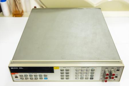
3458A. People who are into precision gear, need no introduction.


I wanted one since long ago, but not having business need in it, was not worth buying, as these even used on secondary market are going for good 3000-5000$ USD. But when I saw one dead unit for 750$, I could not resist and bite it. Seller photos were quite scary, with rust all over steel frame, but PCB boards looked "okay", so I hope for the best.


After some good money for shipping (beast is 15kg weight and size of average 2U rackmount server), I got it and did initial inspection:


* U100 processor MC68HC000P8 had paper sticker BAD (A5 board manufactured 1990)

* Missing button cap and lever for on power switch, guard switch and front/rear switch.

* Missing fuse binding post for amps on front panel

* Rust on steel chassis

* Mark "X" on mains power transformer

* Mark "X" on analog DC board 66501 (manufactured 1996)

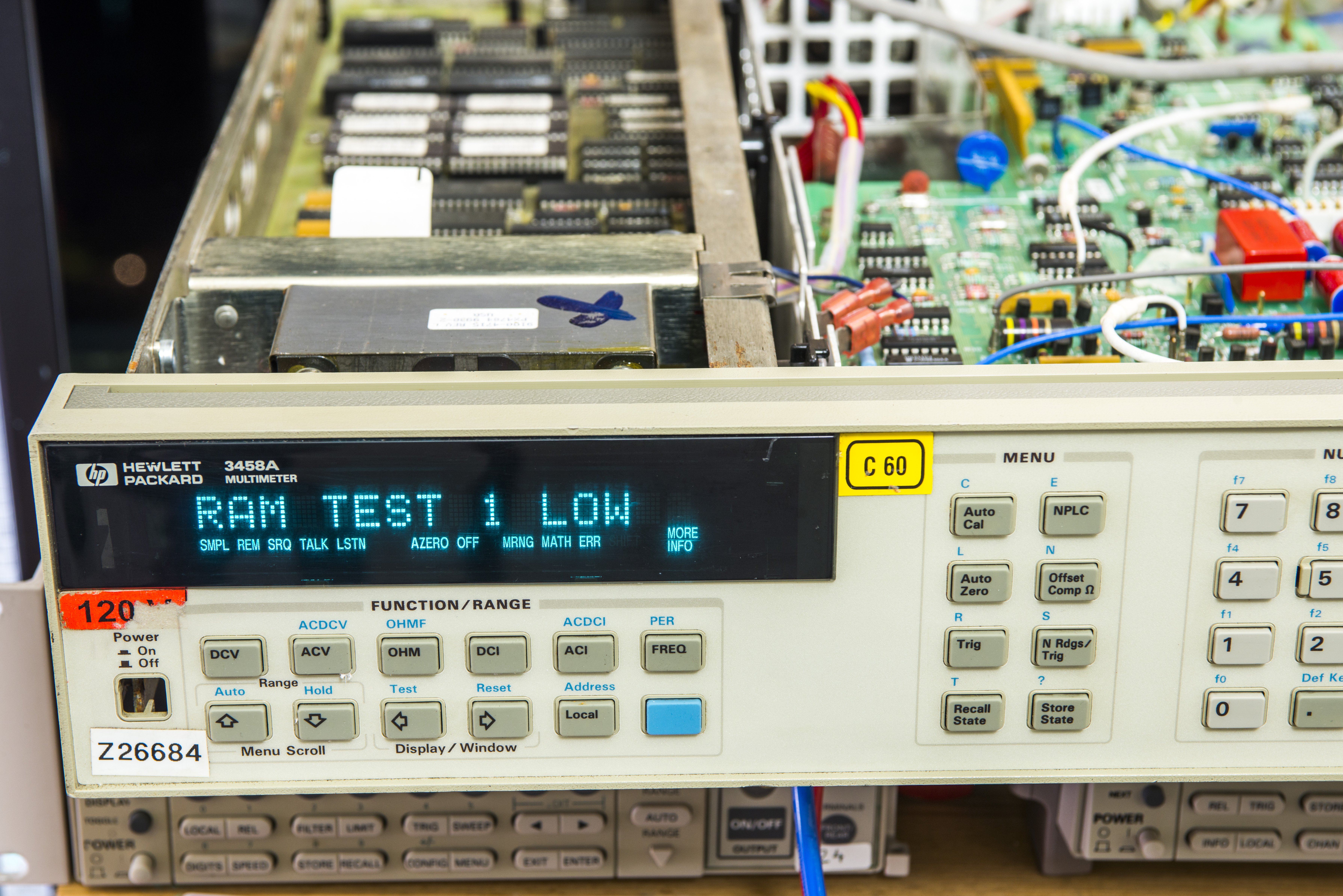
* Error message RAM 1 LOW

* Missing voltage reference board (so calibration is meaningless, even if it's still intact in 1990 year DS1220)..

* Missing fuse holder for mains

* Damaged plastic rear panel

* No legs

* Dead fan

* Likely dead NVRAMs and lost cal as they are way too old.


Smell like lots of work, lots of debug folks.


Let's see what we are dealing with..

imageimage

imageimage

Always sad to see such instrument in mistreated condition. 3458A is current model, and you can get brand new one from Keysight, if you ready to fork 9.5K$, in base configuration.

Let's see what's inside..

imageimage

Cover's removed:


imageimage

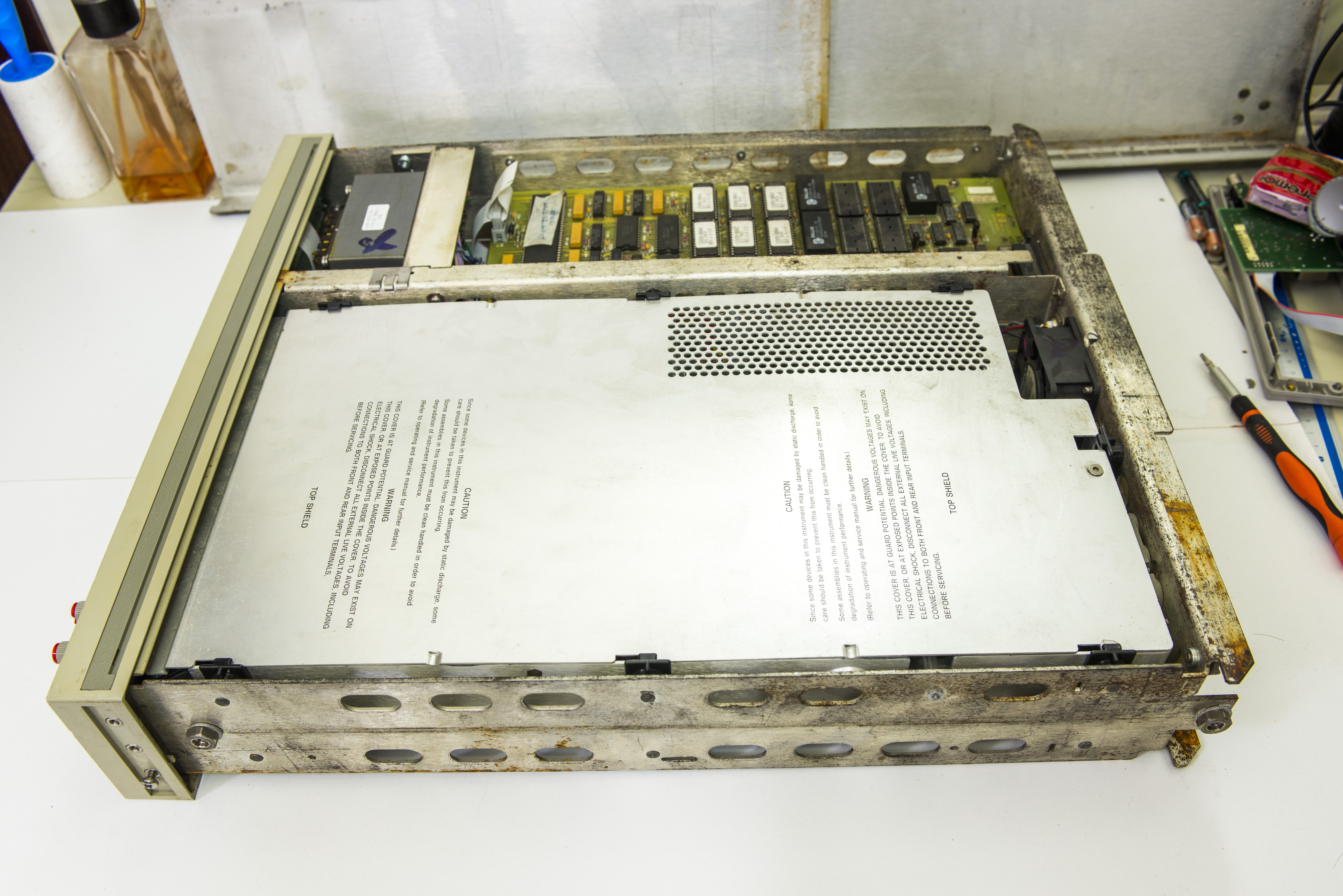
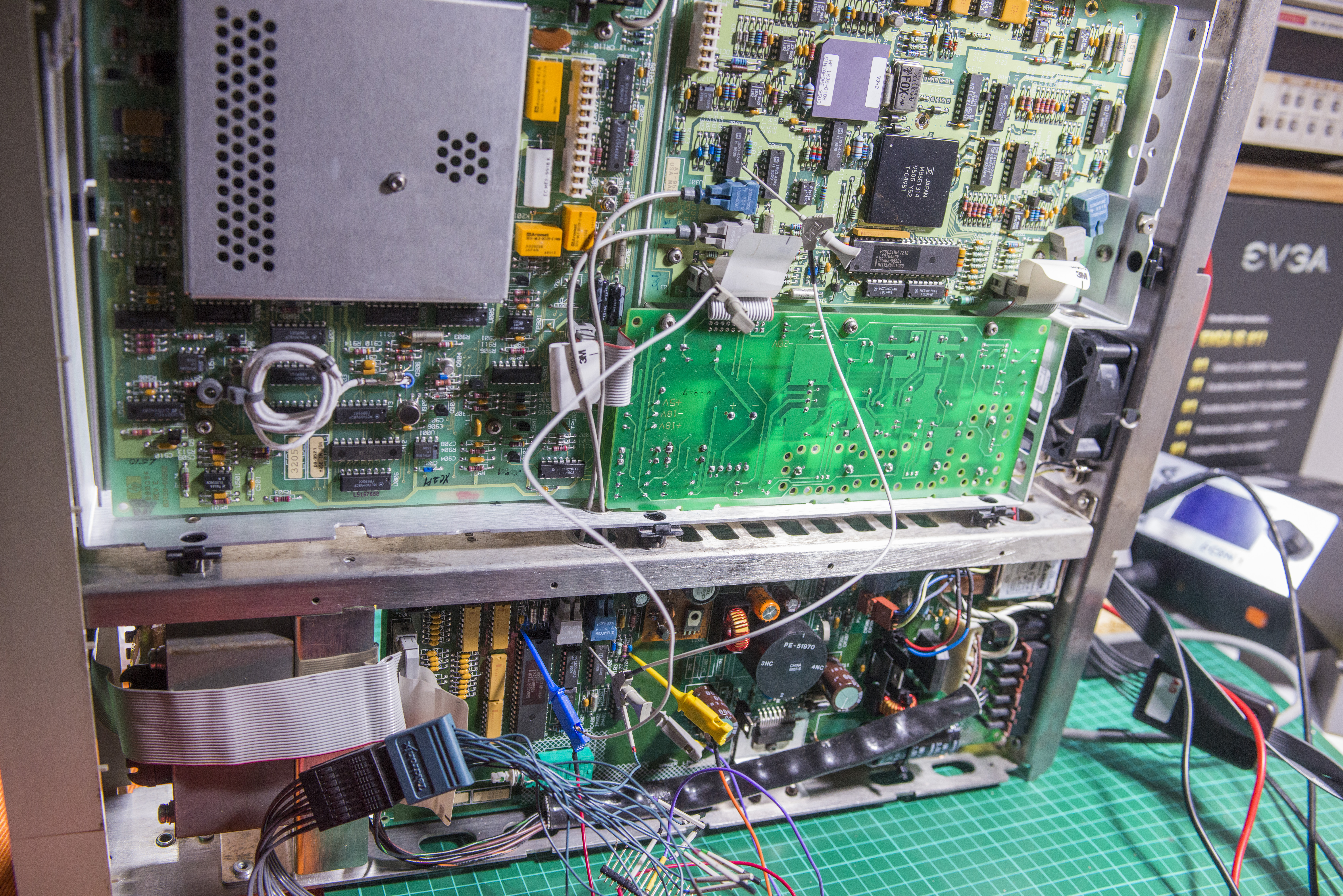
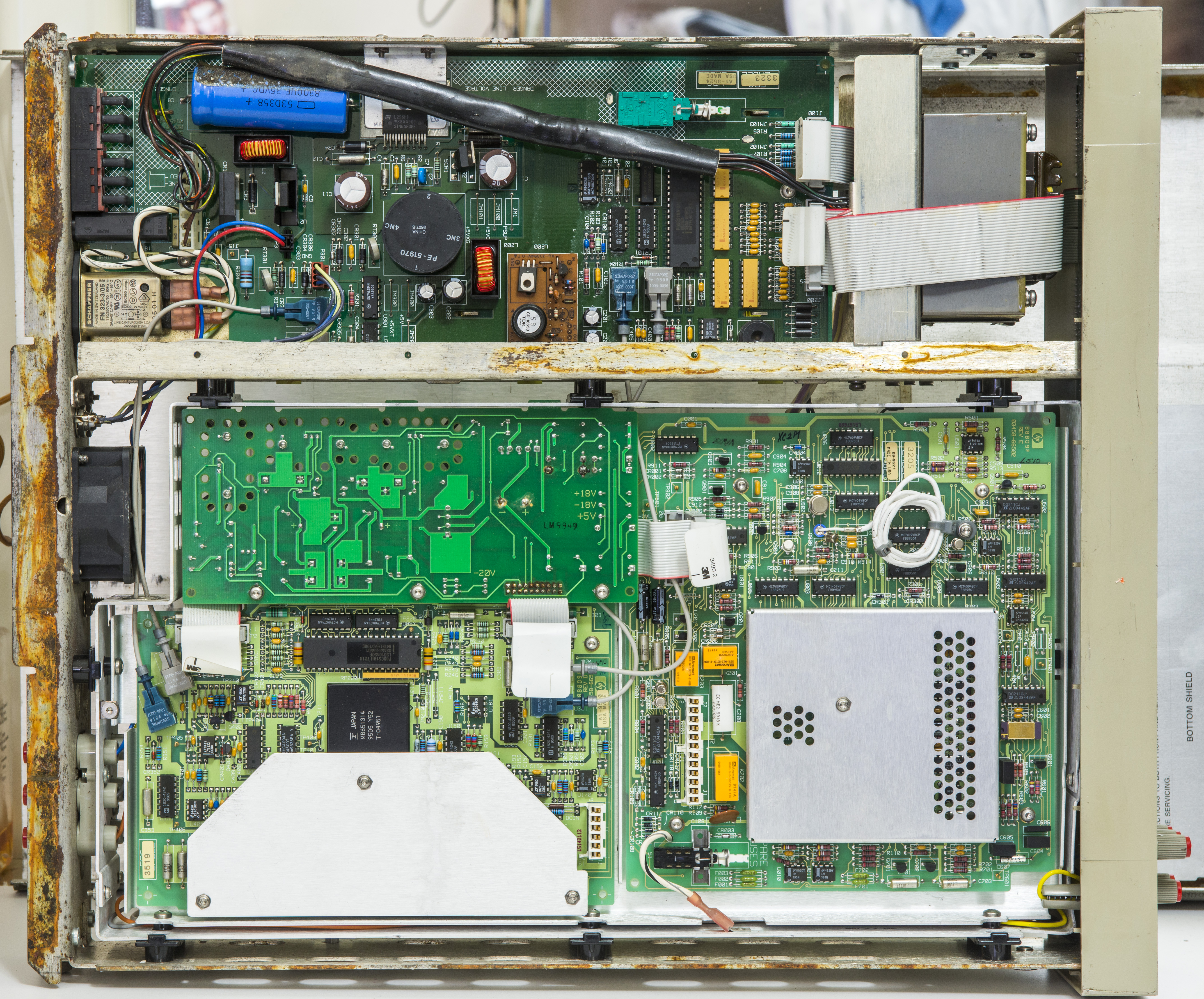
View on both sides without covers. As we can see, no A9 voltage reference with Linear LTZ1000 present. New A9 reference module from Keysight runs for 700$, but hey, I don't need go that way. I had own LTZ1000(A) based references, on which I spent multiple hundreds, and on second source there is eBay, where these references popup for sale like mushrooms after rain. I snagged one of those already , should arrive somewhen next week. So we covered here..

imageimage

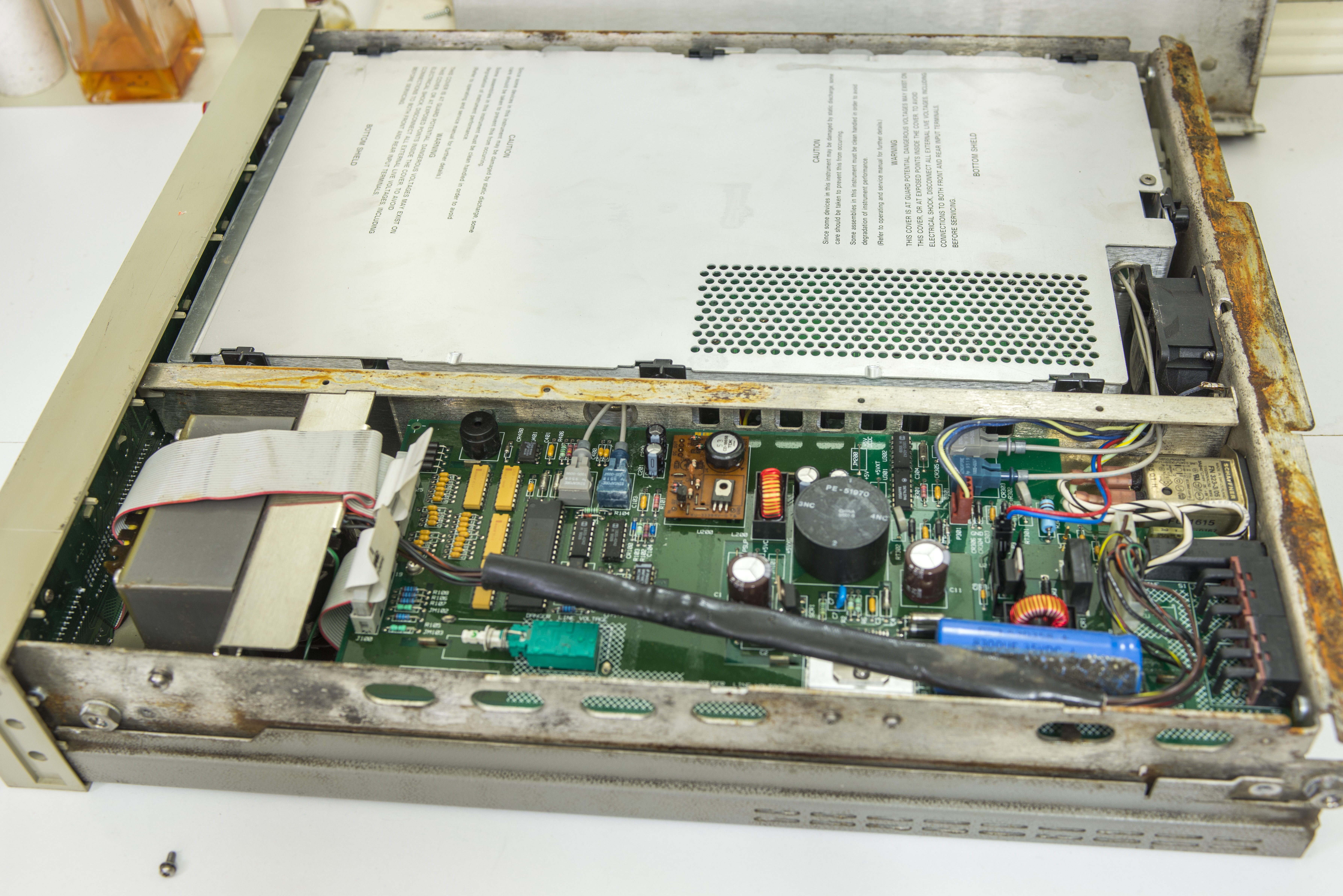
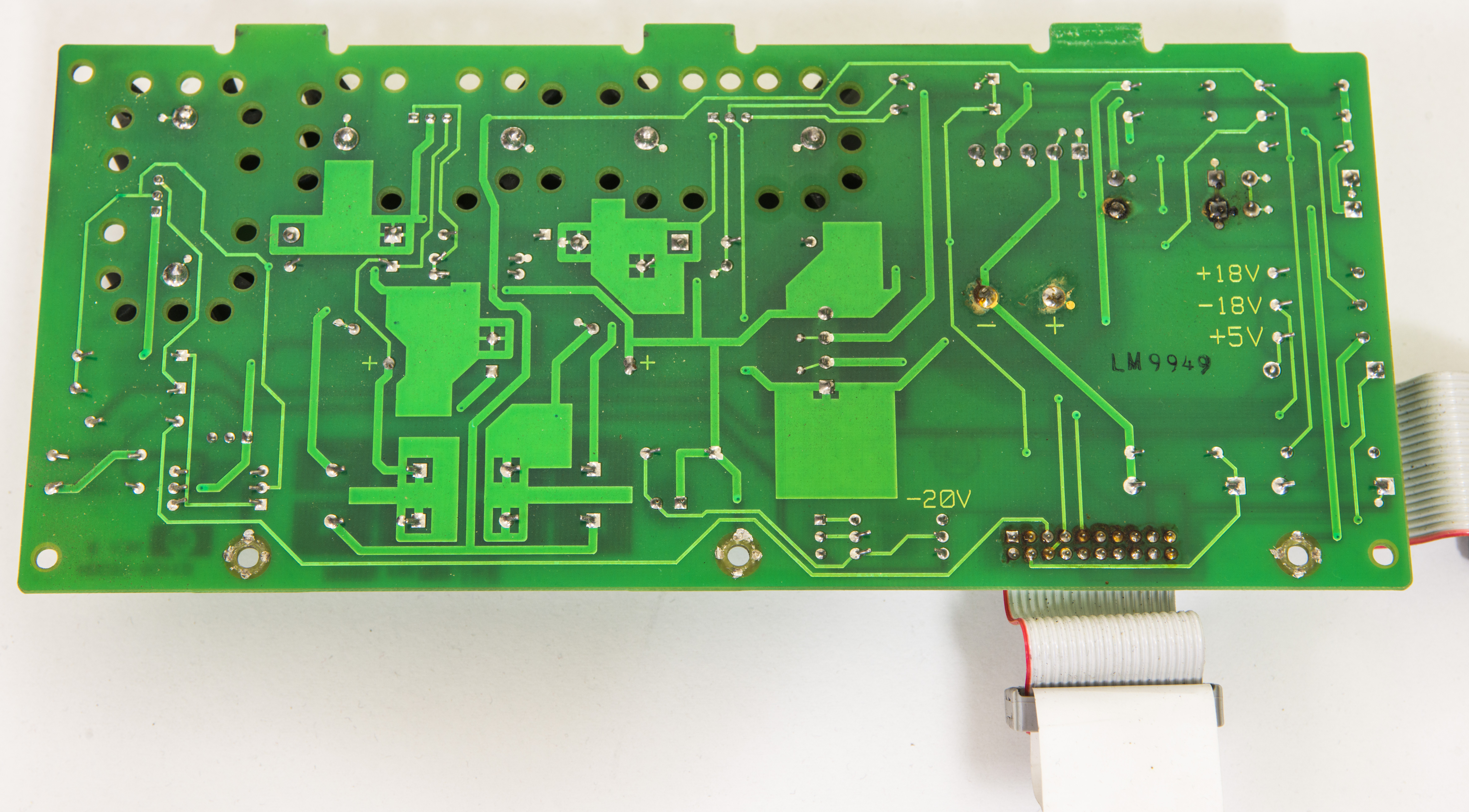
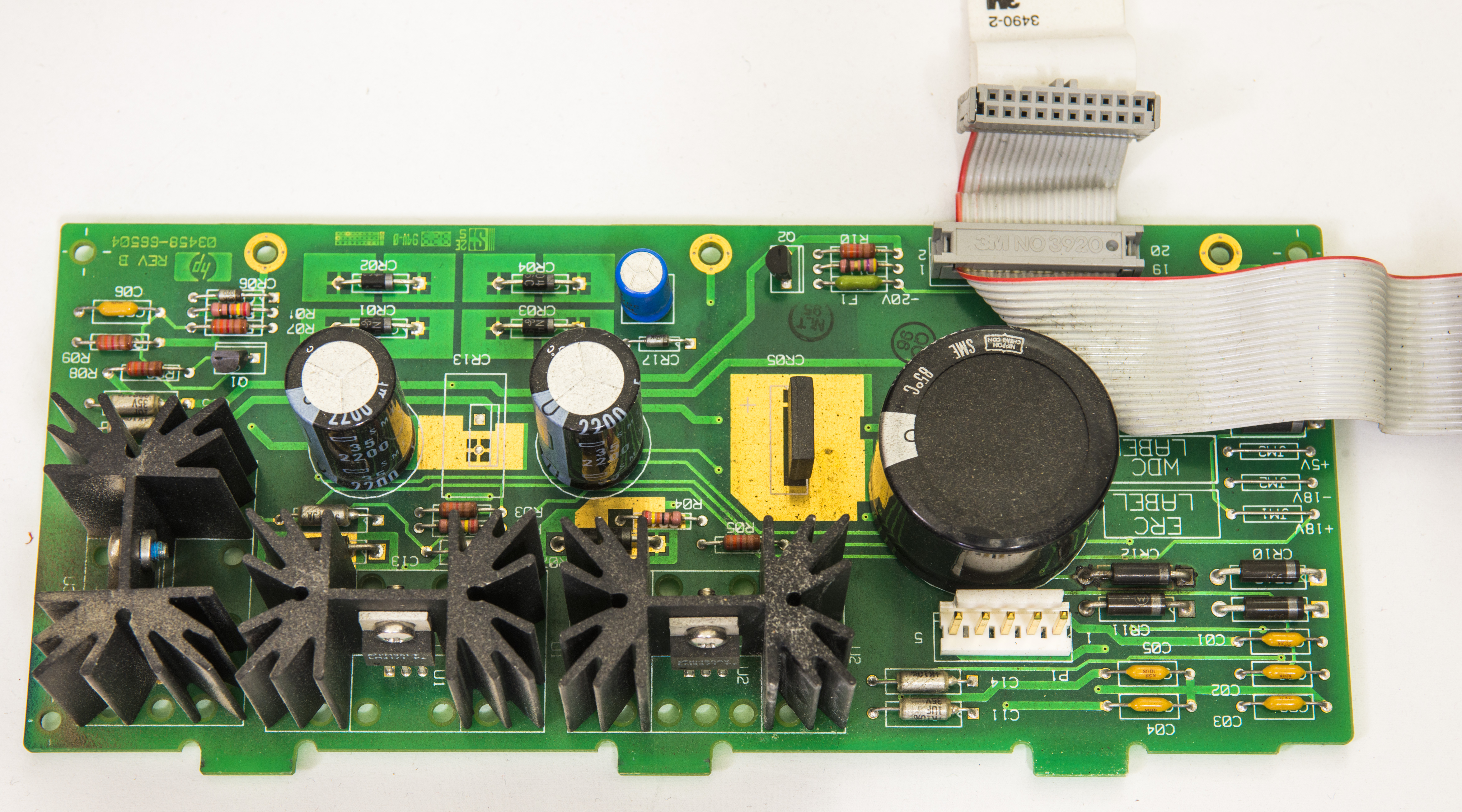
Inguard PSU. Some PCB damage around CR12 visible.

imageimage

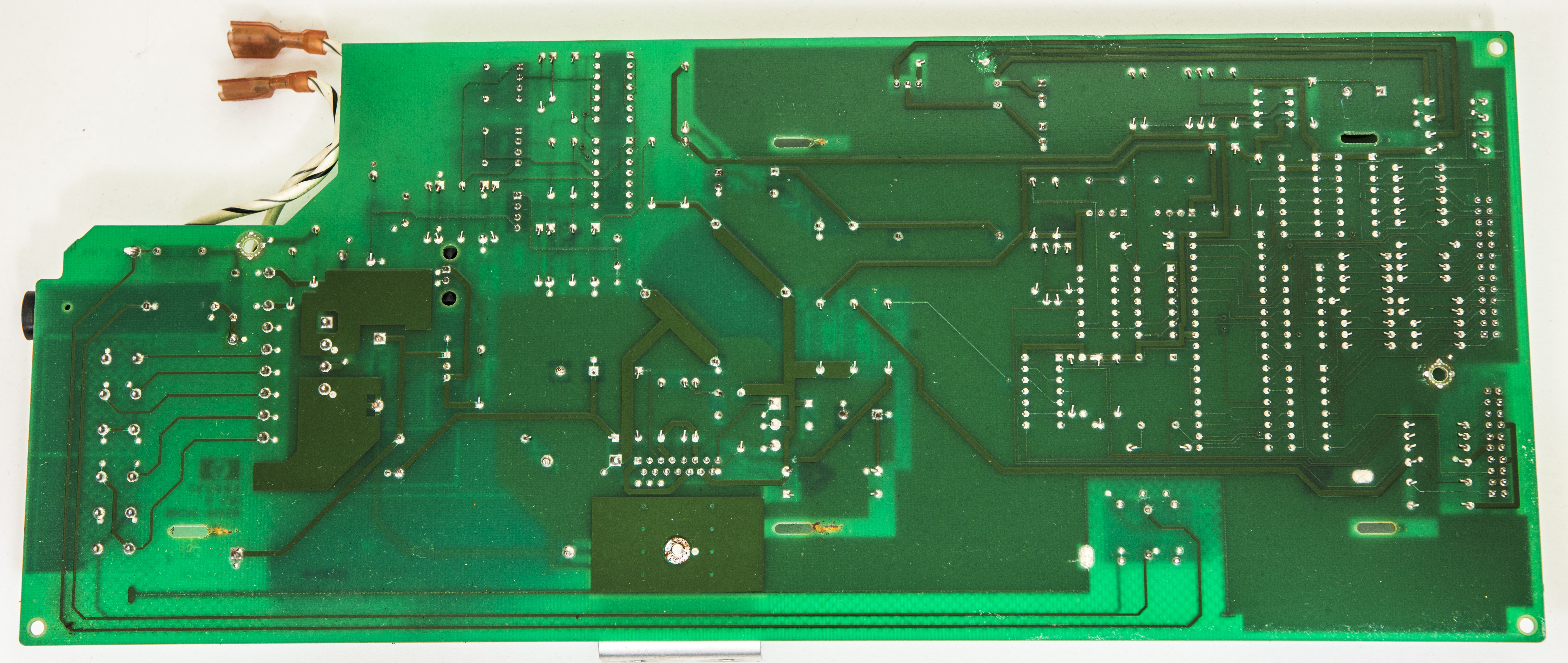
Outguard primary PSU. All seems ok, but need cleaning..

imageimage

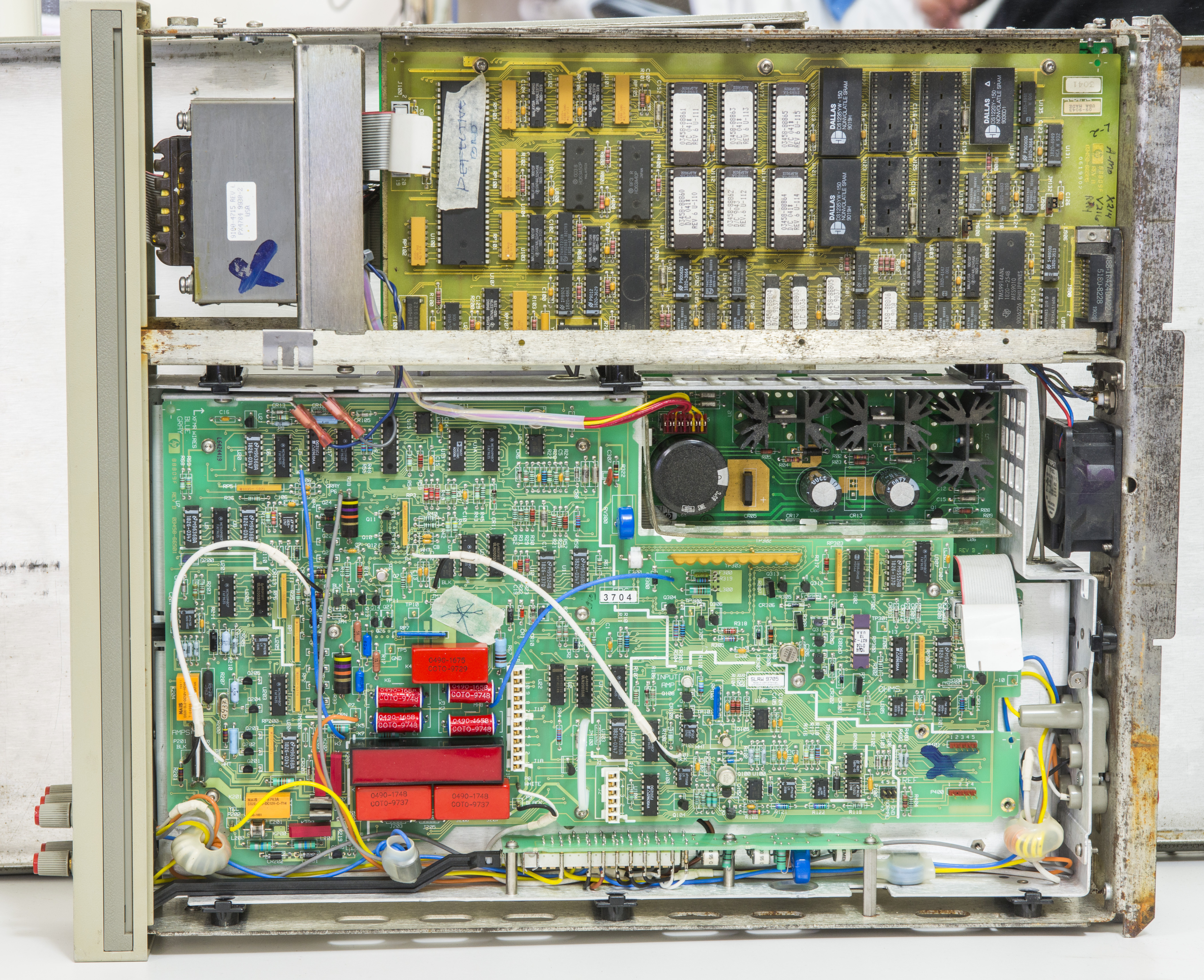
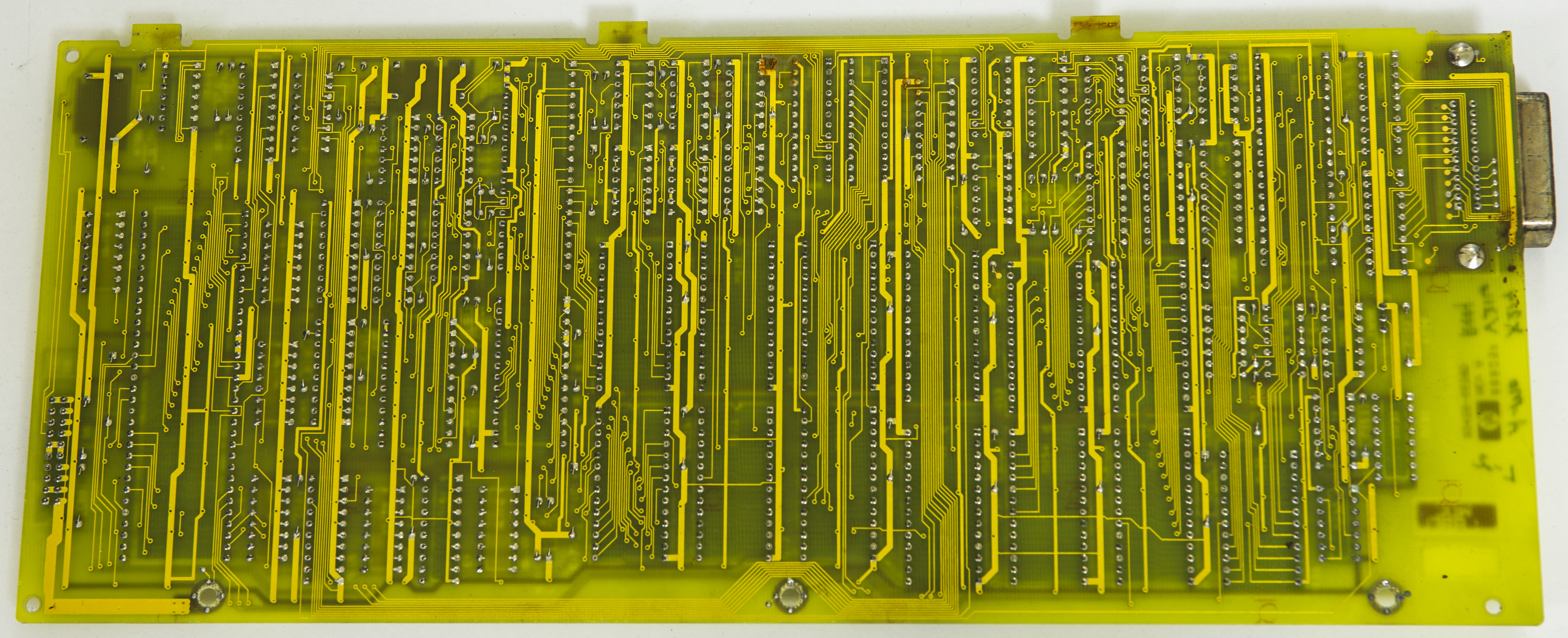
68000 CPU, RAM, ROM and digital logic, board A5. Dated 1990, while rest of analog PCBs dated 1996.

Probably seller changed digital PCB afterwards?

imageimage

Removing inguard PSU for now, adding jumpwire instead of fuse (don't have suitable cap), turning on...

image

It's works!.. Well, not really image Analog side completely disconnected and unpowered at this moment, just check digital and power sections first.

Nice and bright VFD, which is good, as it's hard to get replacement for those.


Now will remove Dallas NVRAMs , and solder sockets instead, so we can troubleshoot this RAM 1 LOW.


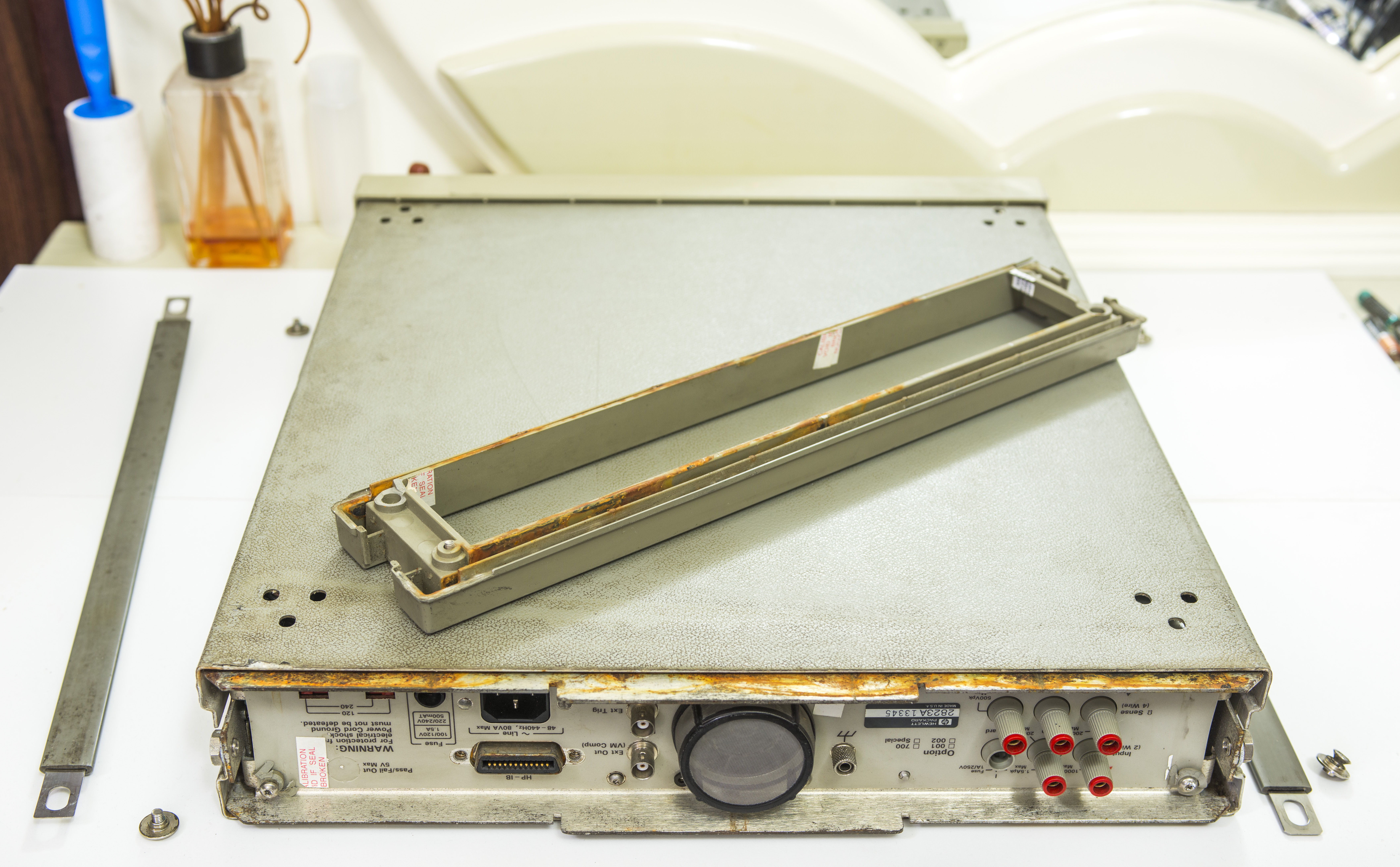
Front panel must be removed in order to remove mains transformer.

image

image

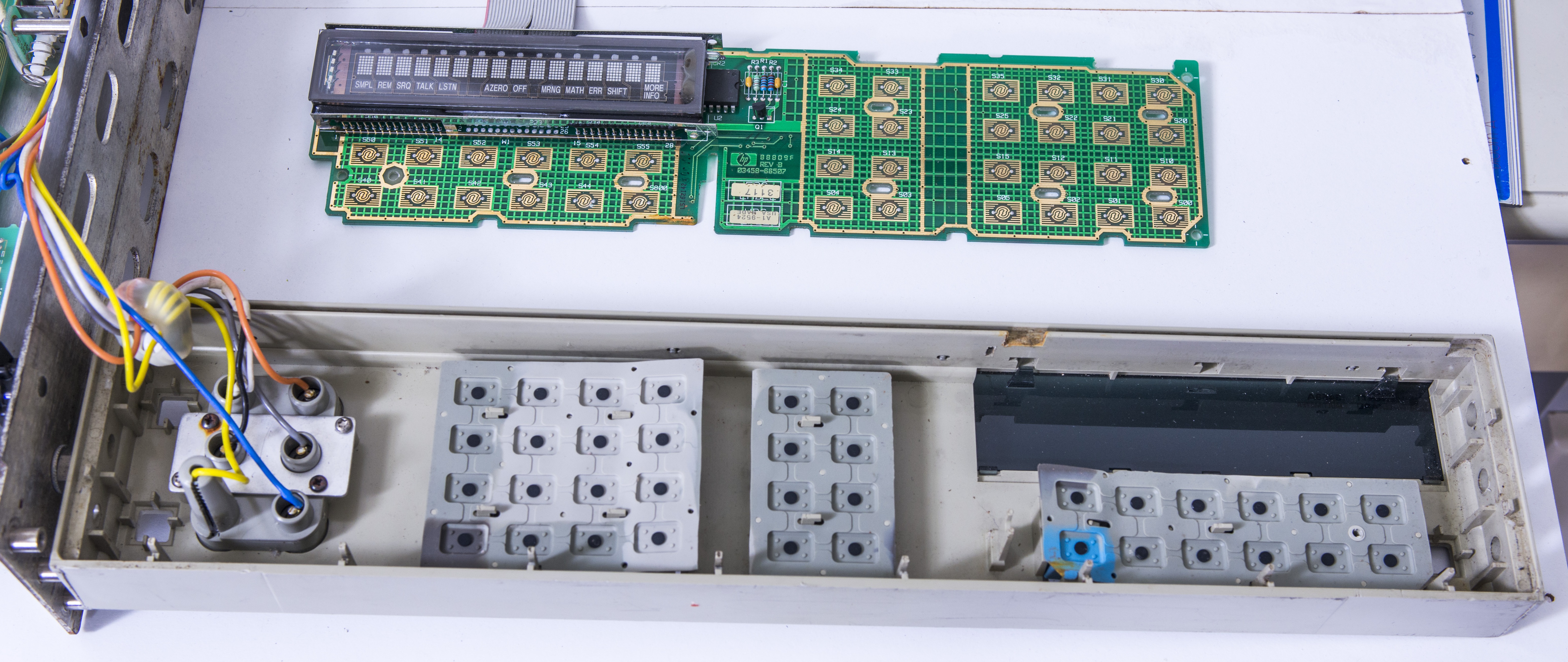
Looking good, just minor cleaning required..

image

image

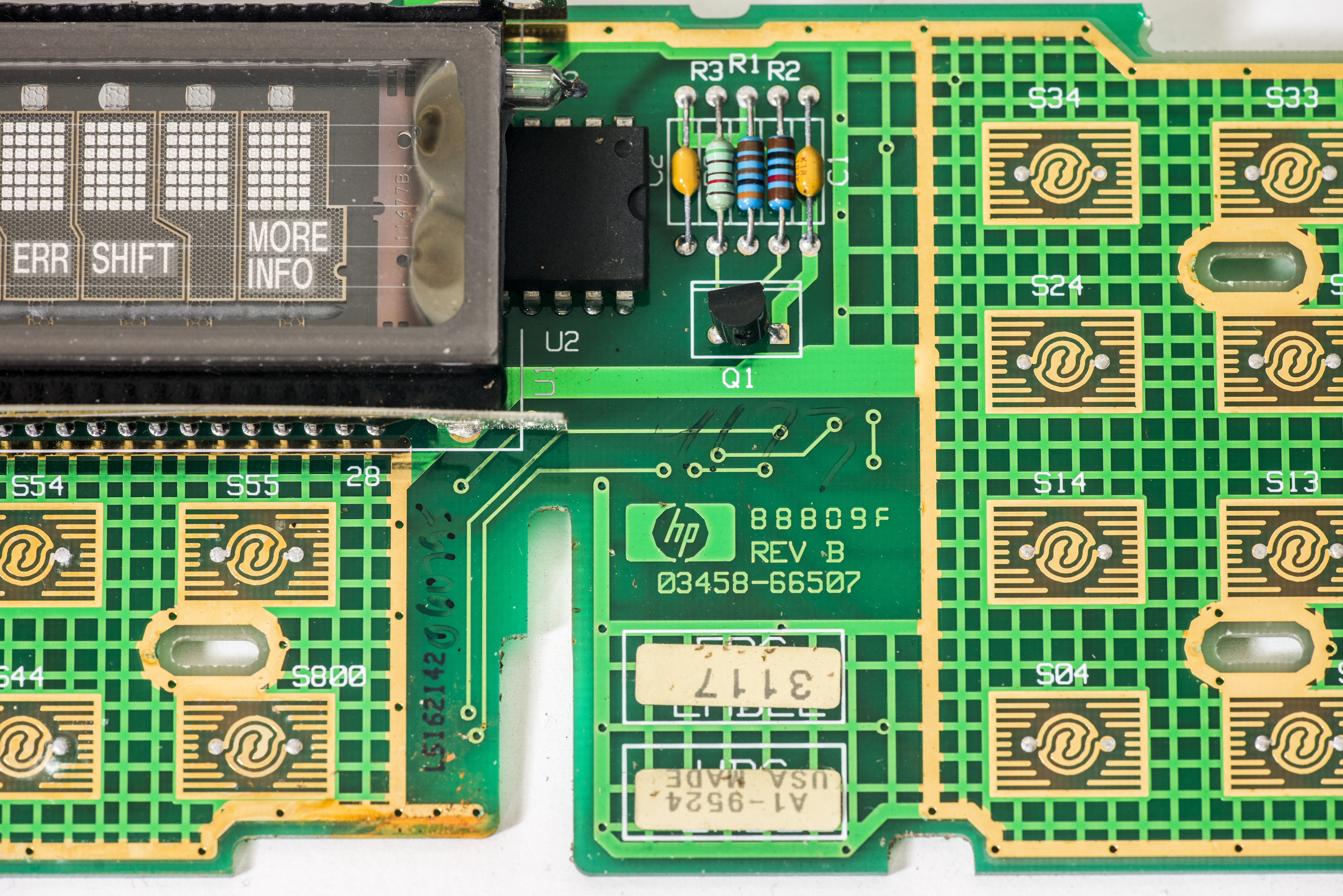
Frontpanel PCBA label and front binding post terminals.


Now, we can take transformer out. I tried to open it up, but it's all covered in lacquer, and my patience run out quickly after wasting a hour trying to take it apart.

image


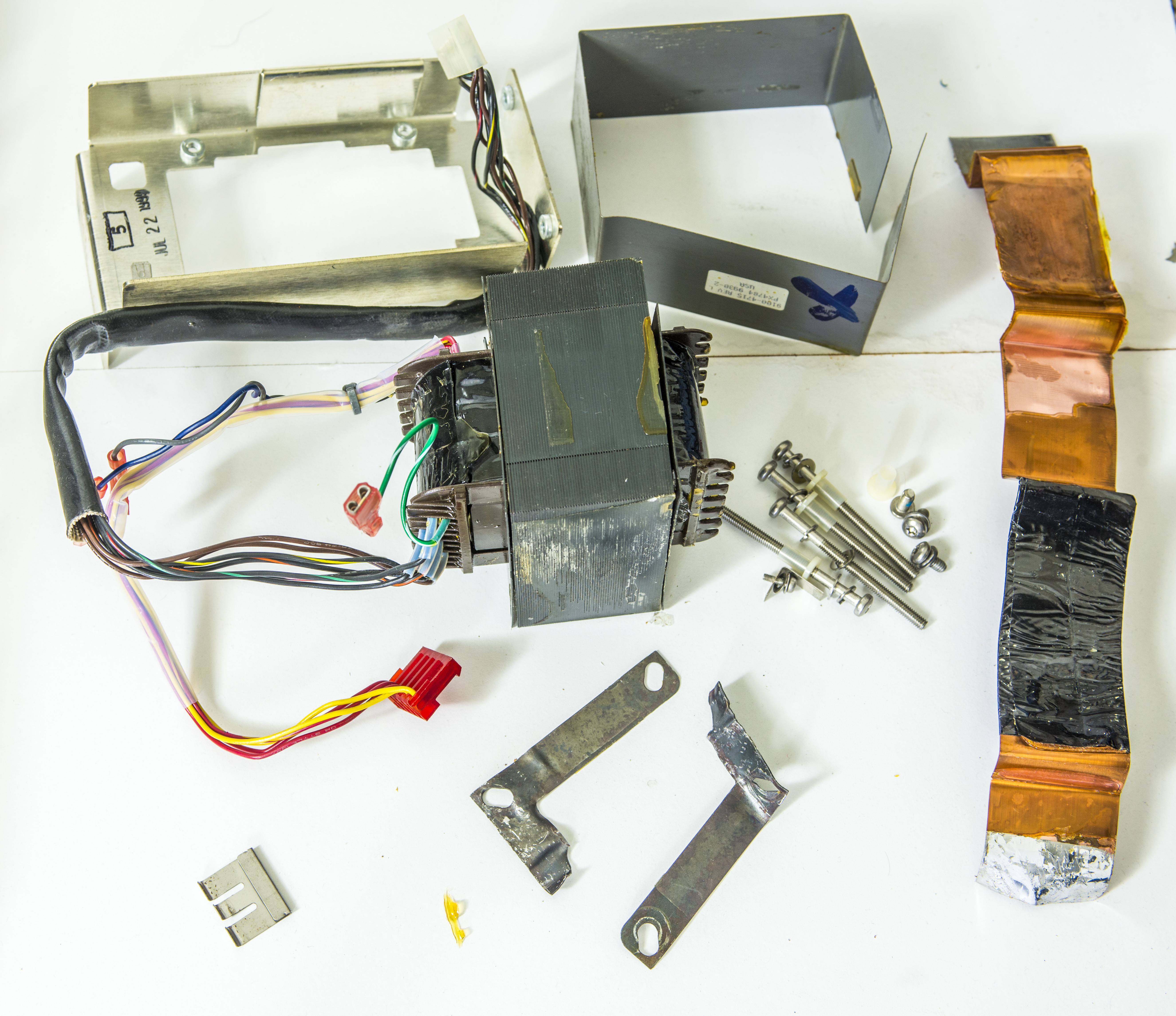
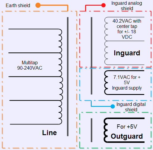
Transformer have two winding sections, primary with secondary for outguard +5V rail (goes to digital board and front panel, that's why it's working).


Second section for inguard supply is inner bobin with two secondary windings (one with center tap to generate +18/-18 and second for +5V analog).

This windings in my transformer are shorted together!


image


I would not trust repaired/rewinded transformer in such an instrument anyway, so going to make Agisight richer for $337 to get new transformer.


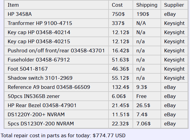
In case someone got FALSE impression that buying dead HP 3458A and fixing it would be cheap way to get yourself 8.5-digit DMM, think again.

Here are expenses on my unit already so far:

image.

Add calibration (let's say you go full tilt, standard's grade cal $2660), and you looking into healthy 4.4K$, for which you can get working and likely even calibrated 3458A from second-market, if you patient and shake trees good enough.

Also you can see I cut few corners here and there with parts from eBay, as if you go with all original parts from Keysight, it will be much more (Reference board alone is 700$, like mentioned before).


Since I wait for new transformer to arrive, how can we test inguard supply to confirm it's OK?


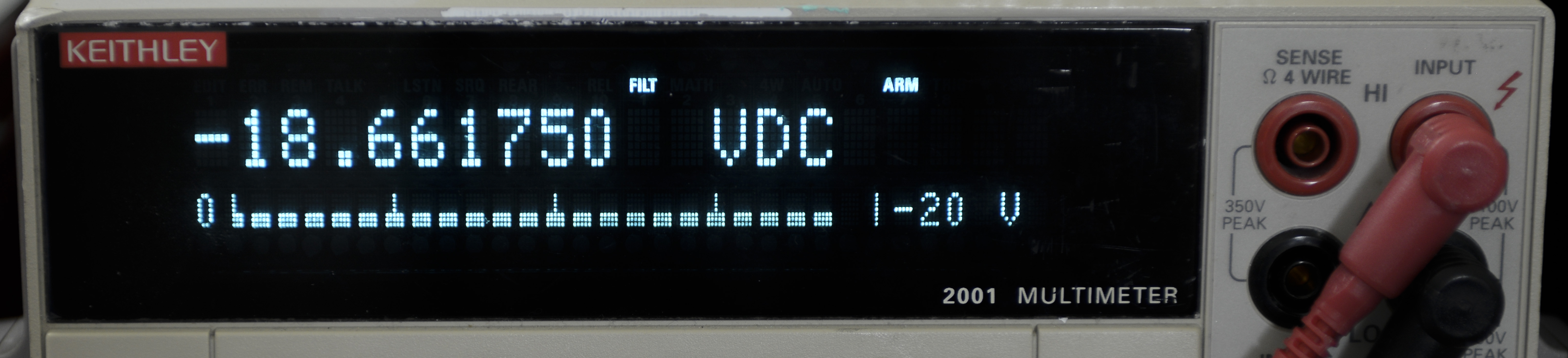
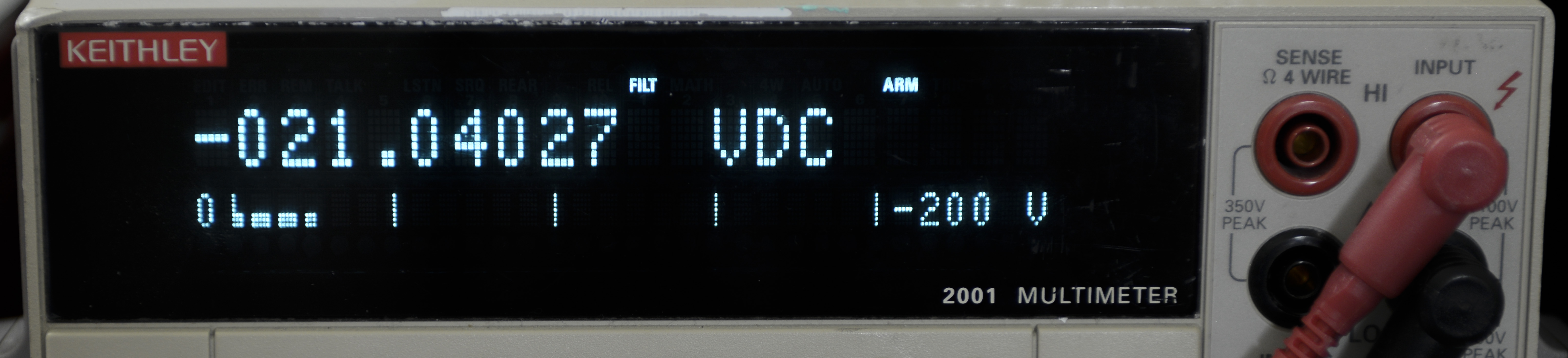
I have a "solution". From previous Keithley Model 2001 repair projects I have one extra power transformer, which happen to have same voltage outputs, as HP one, just at lower power rating. But since we connect only inguard supply A4 board, we don't need full power to check LDO's  operation. So let's replace blown zeners and test A4 PCBA with properly wired Keithley mains TR-280 transformer. Never know which parts could ever come handy, eh? 

But first, replaced original CR11,CR12 with fresh zeners (got 50pcs from eBay, just few dollars with free shipping).

image

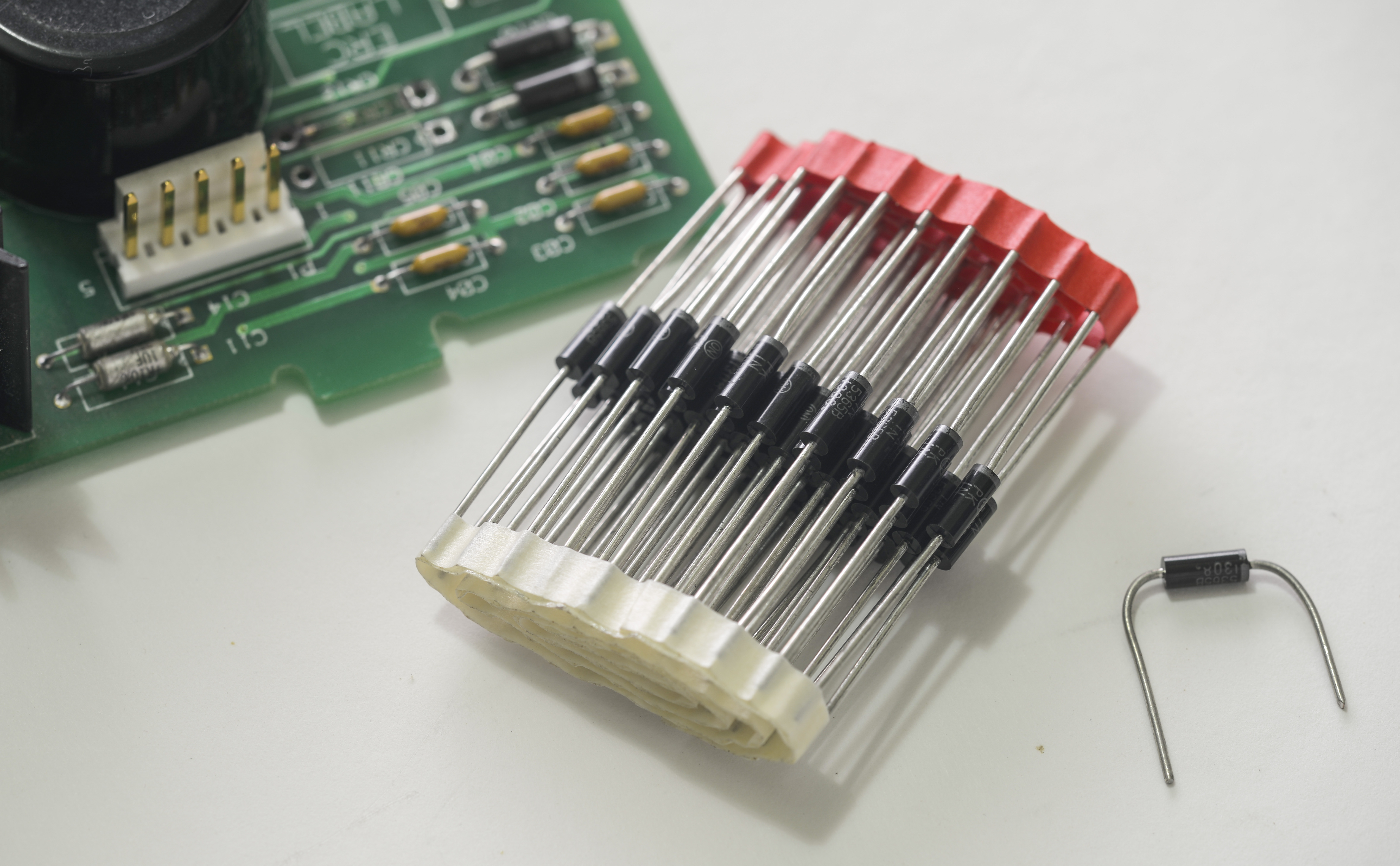
Cleaned board both sides, everything else look intact and good.

image

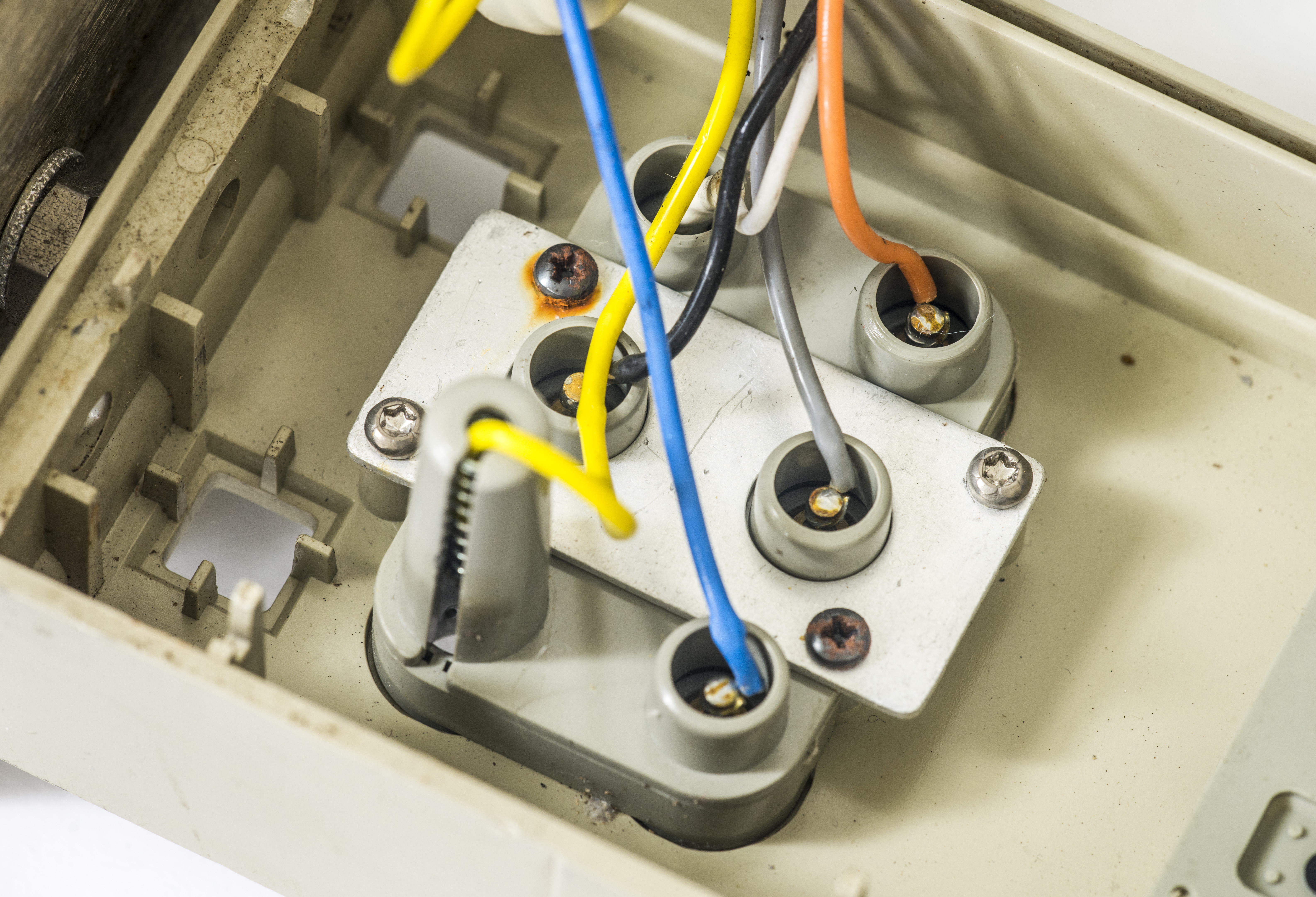
Now can connect input IEC plug socket to transformer's primary (since I need 110VAC, I used WHITE + BLACK wires).

image

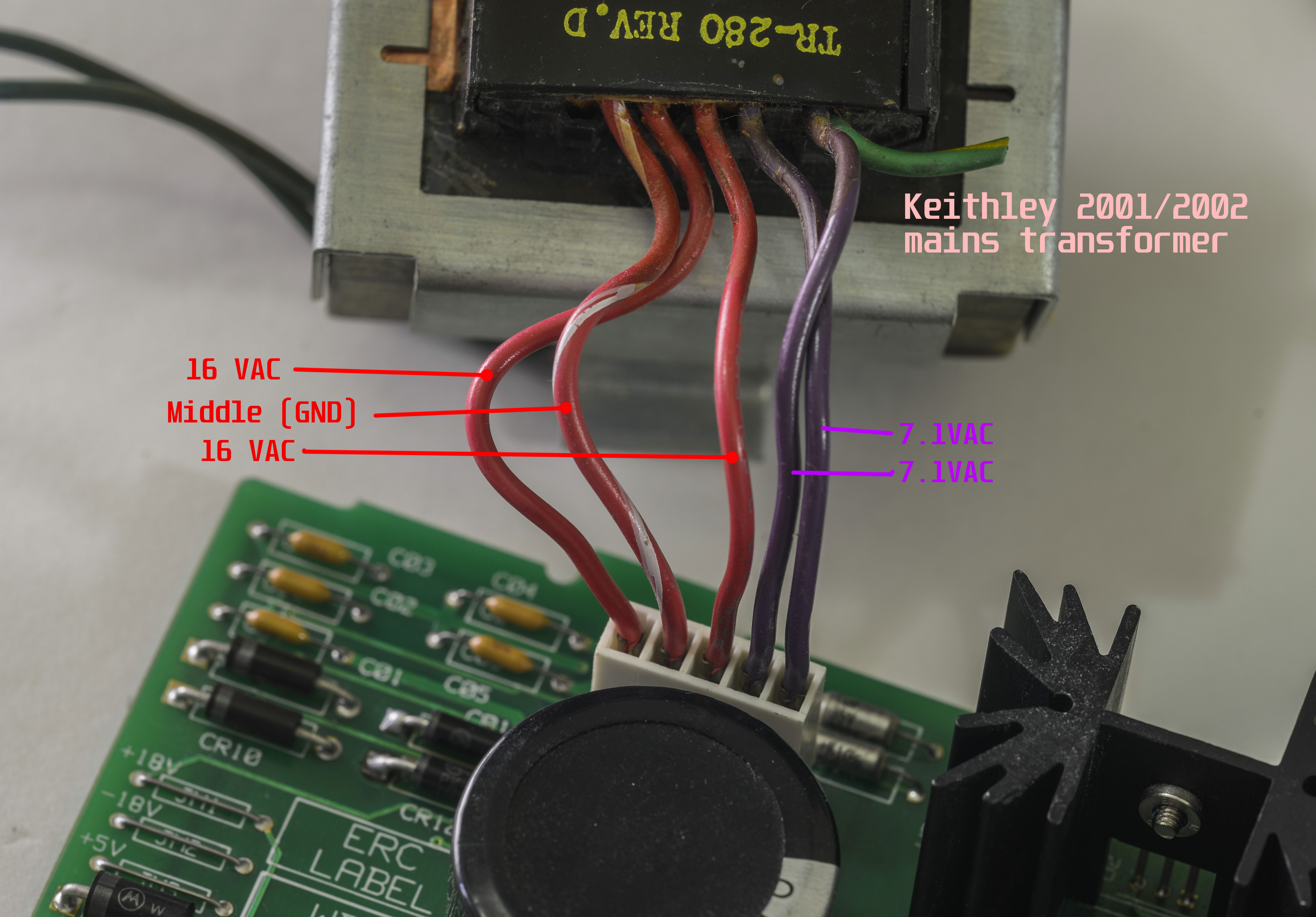
Keithley used same type of 5-pin connector, but with different pinout. Secondary connector need rewiring as on photo above. I powered transformer separately and measured VAC voltages on secondary, without A4 board connected, to make sure all voltages correct.

image

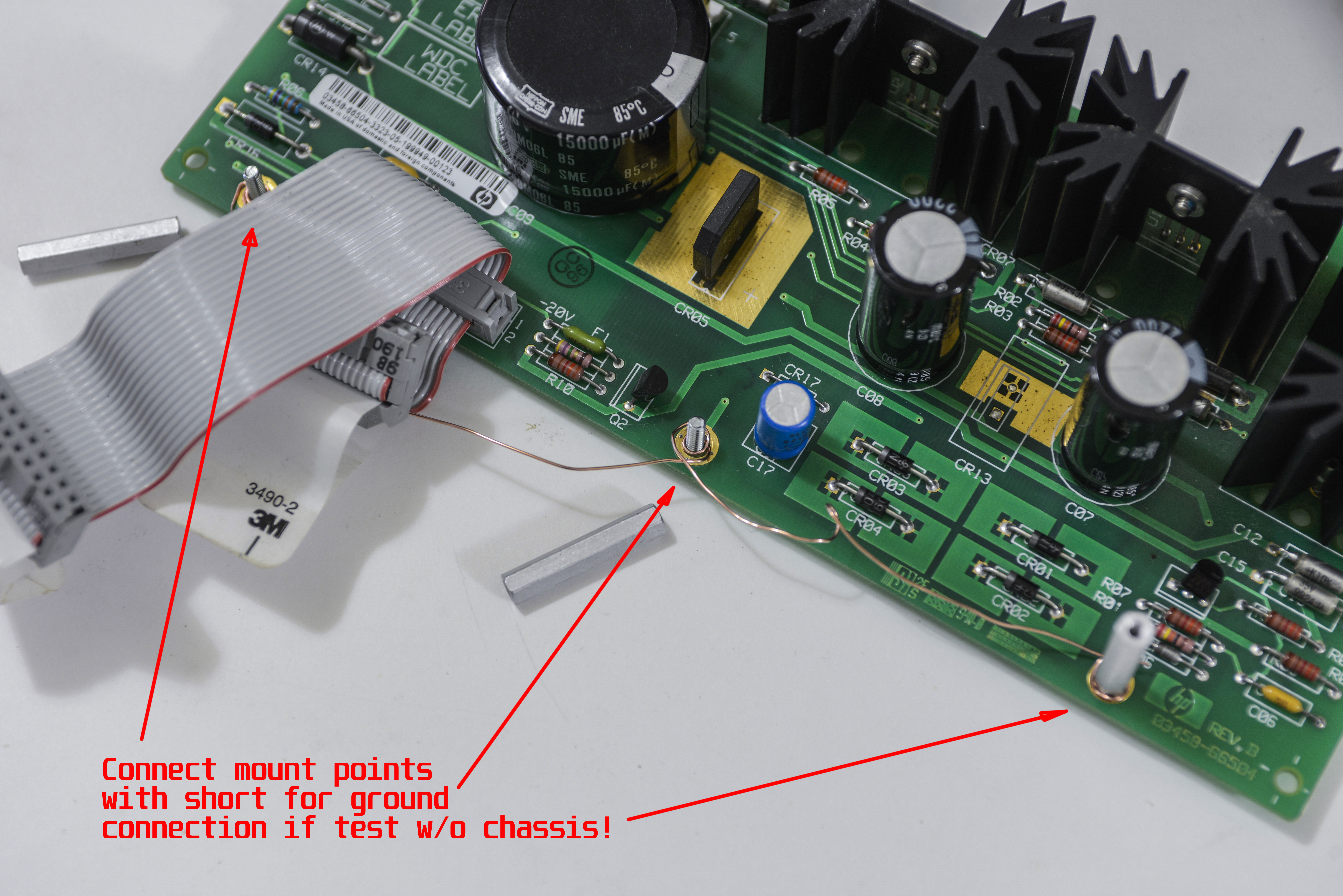
If you see schematics of A4 board in 3458A Multimeter Component Level Repair Manual, you may noticed MH1,MH2,MH3 connections. These are connected directly to guard frame in 3458A's chassis, which is acting as mecca star point for GND potential. Since I testing board separately, not mounted to chassis, I needed to connect these MH* points together with copper wire. This will be our ground point for measurements as well.


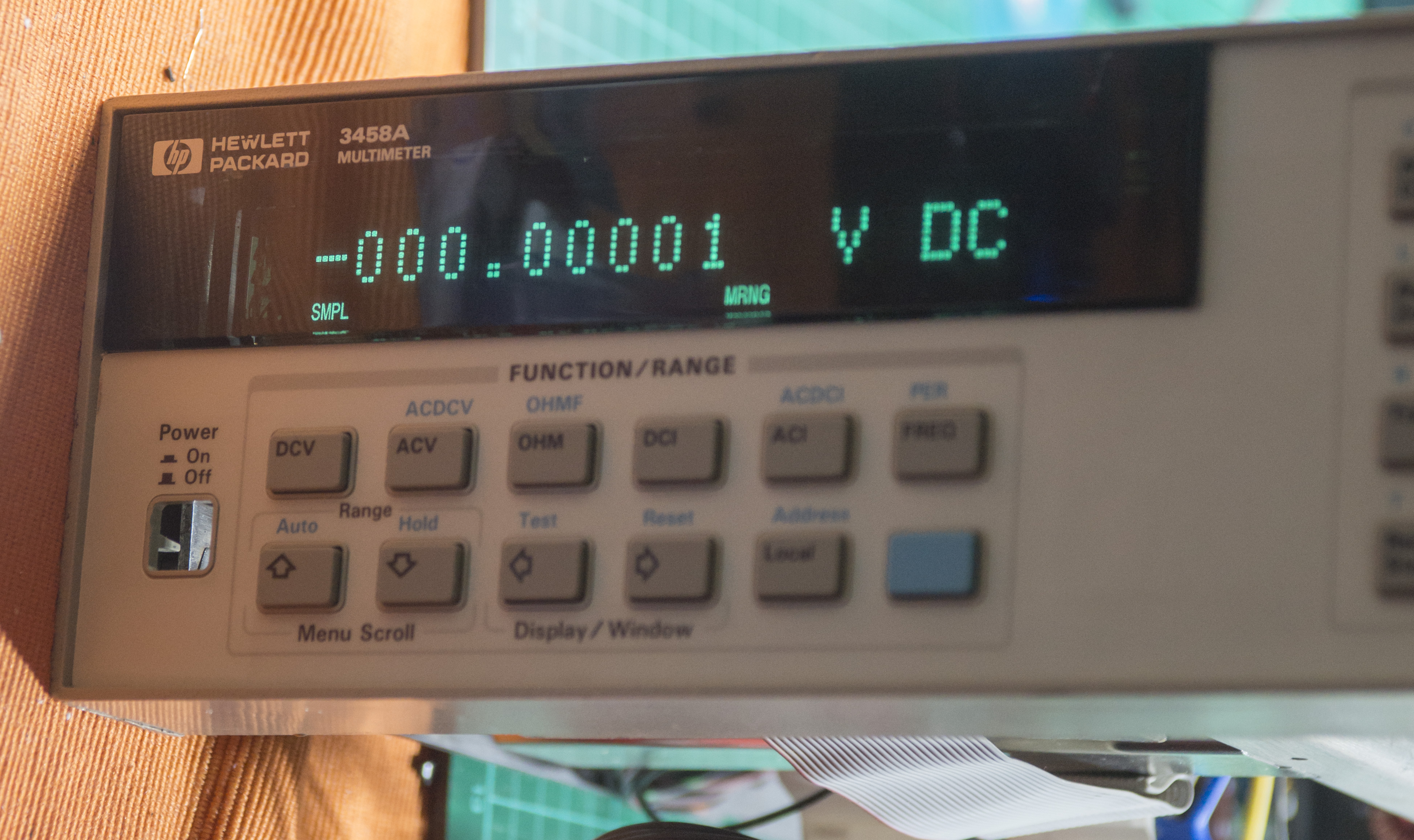
Apply power to transformer, and if nothing smokes, test output DC voltage.

image

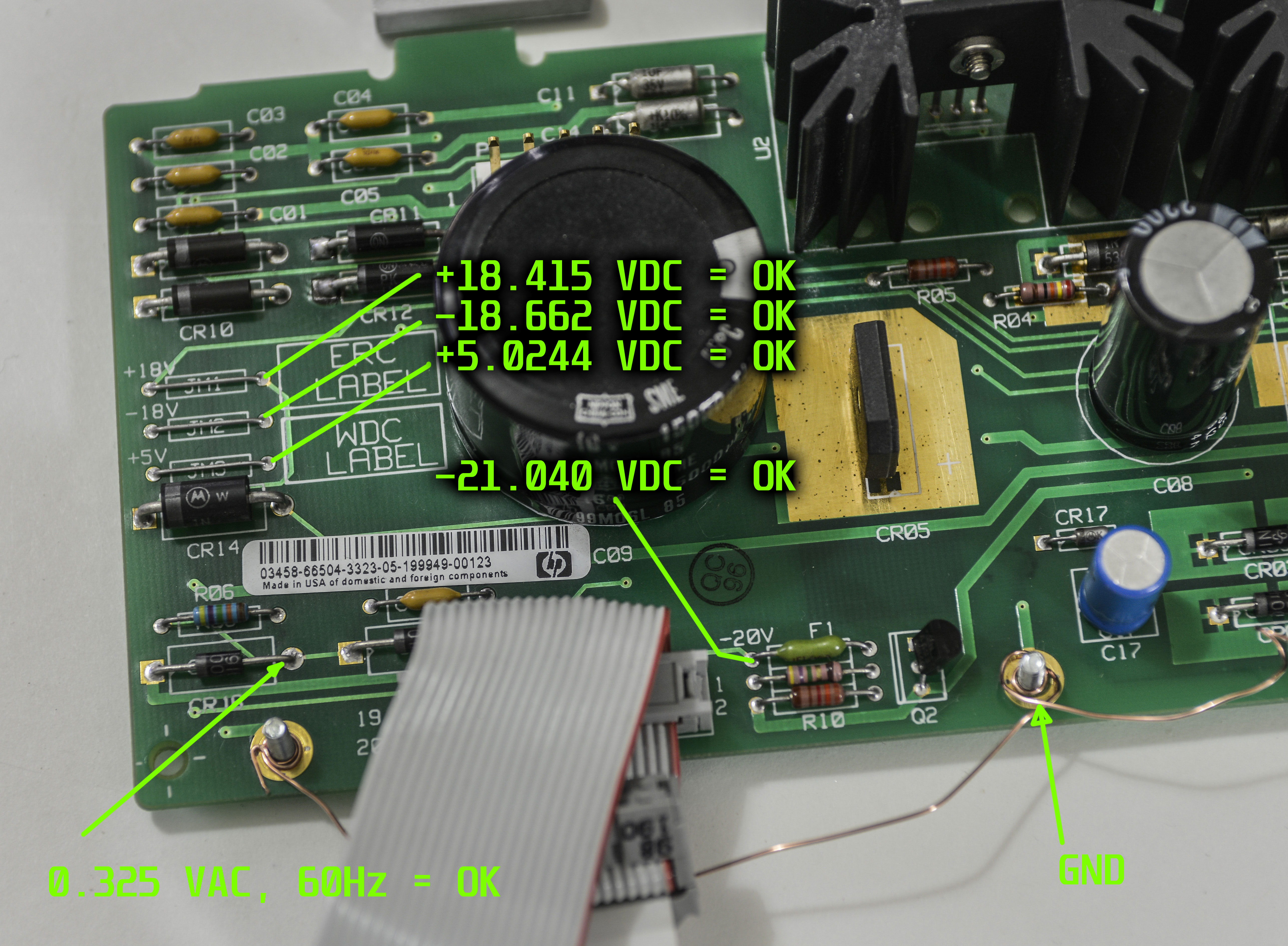
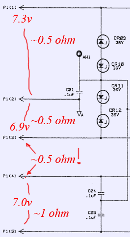
There are nice labels near test points, telling us voltage test points location.

imageimage

imageimage


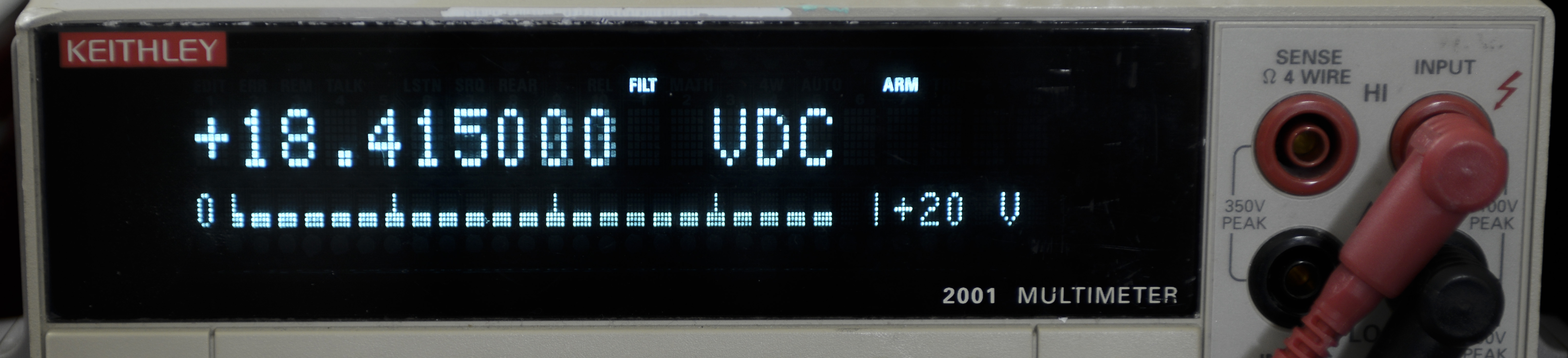
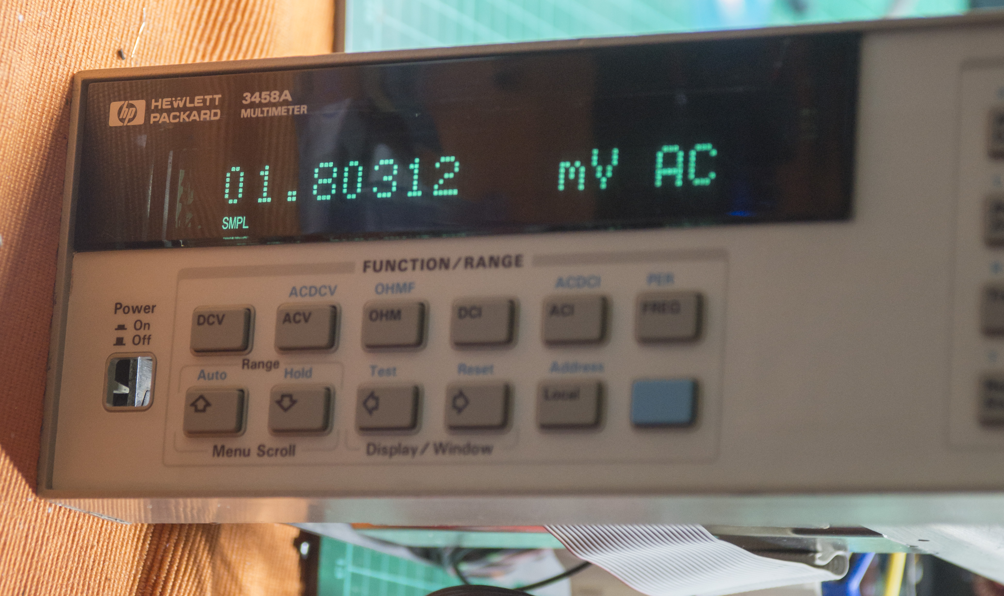
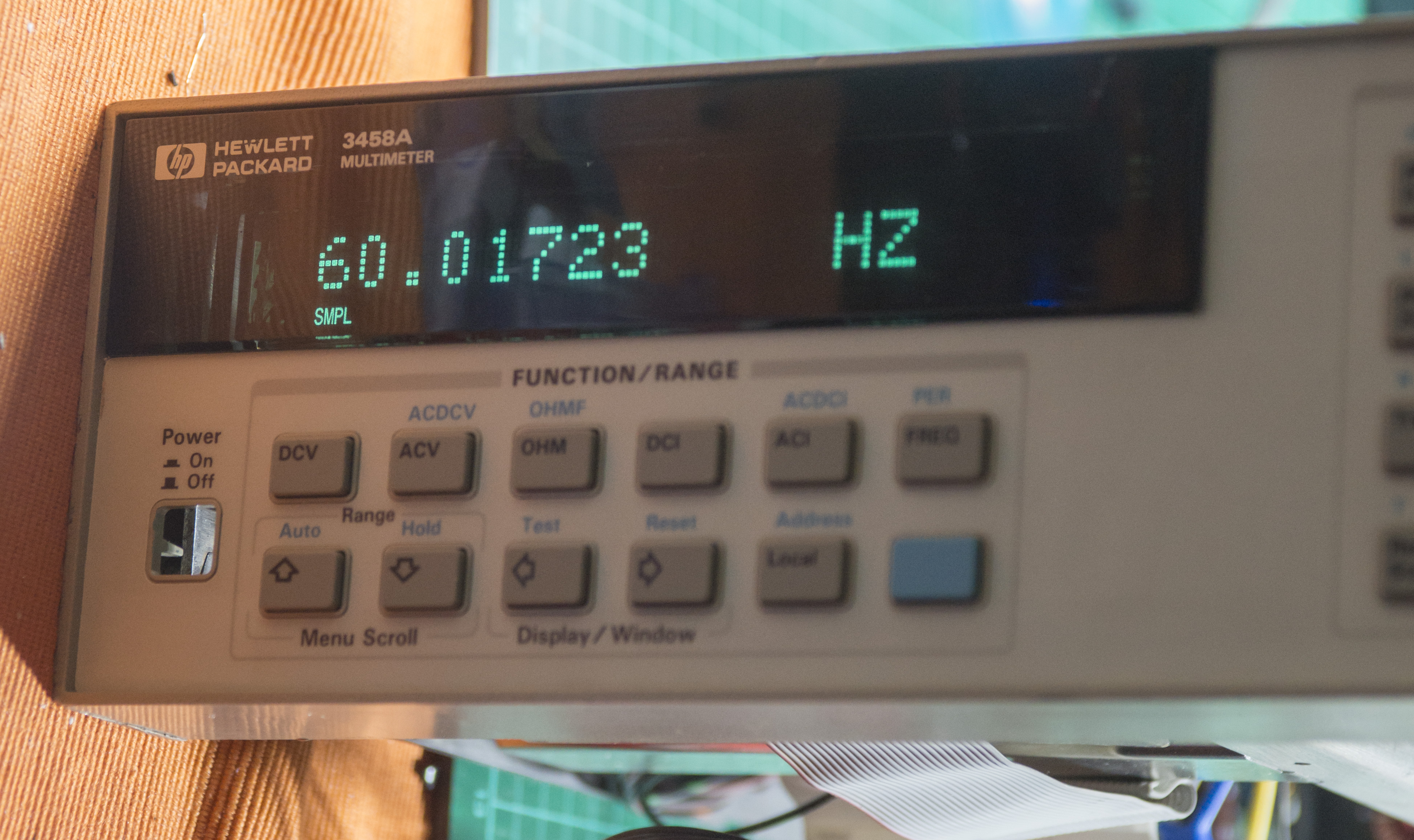
All voltages are OK, also 0.325VAC 60Hz signal to read mains frequency is OK too. 

Repair of A4 inguard power supply now complete.


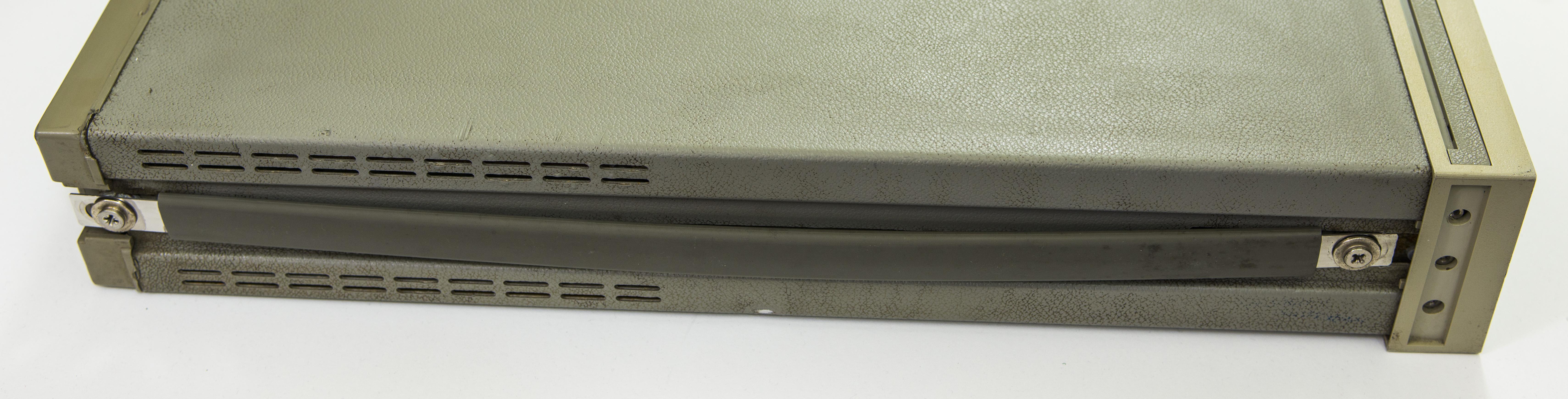
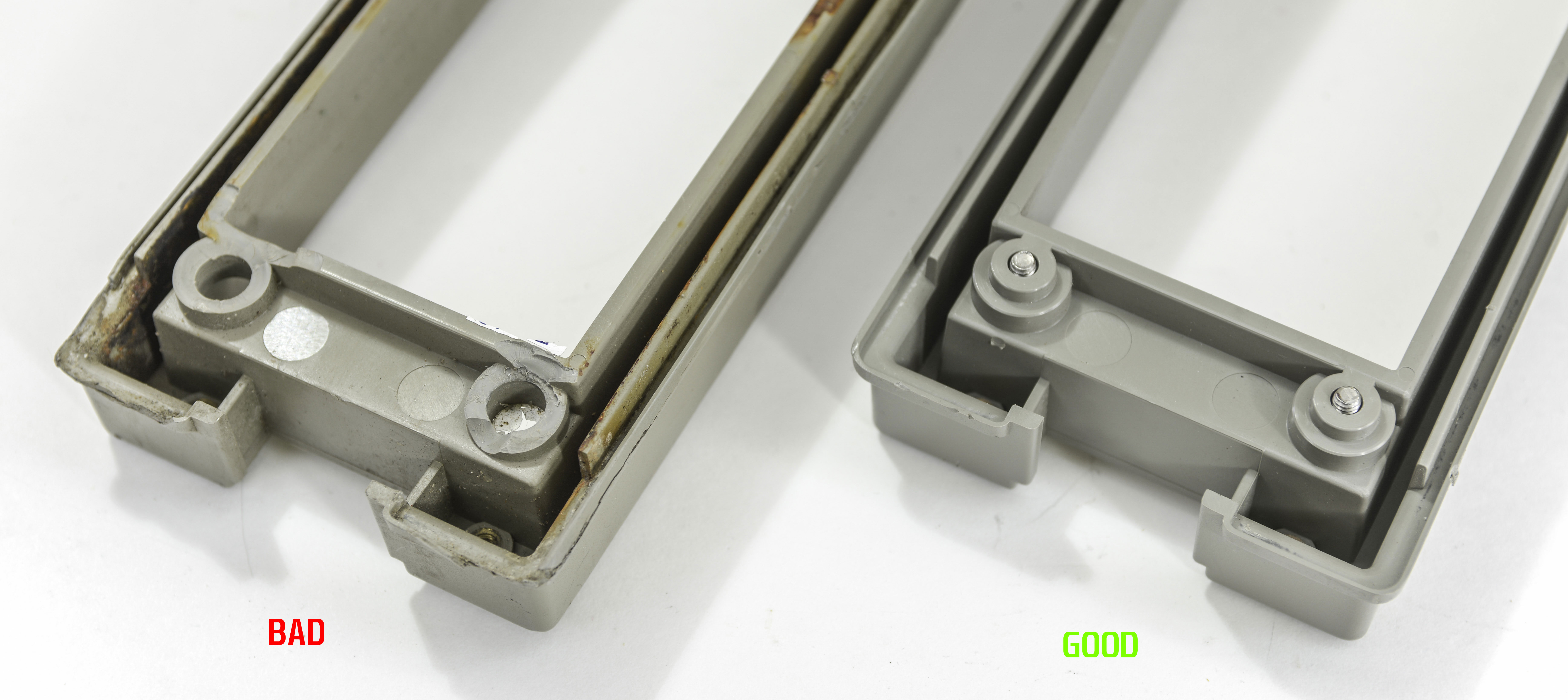
I also got used bezel off eBay in good condition, to save some money on this project, as it's just mechanical part to keep meter in one piece.

New one on bottom side, old busted rear bezel is on top.

image image

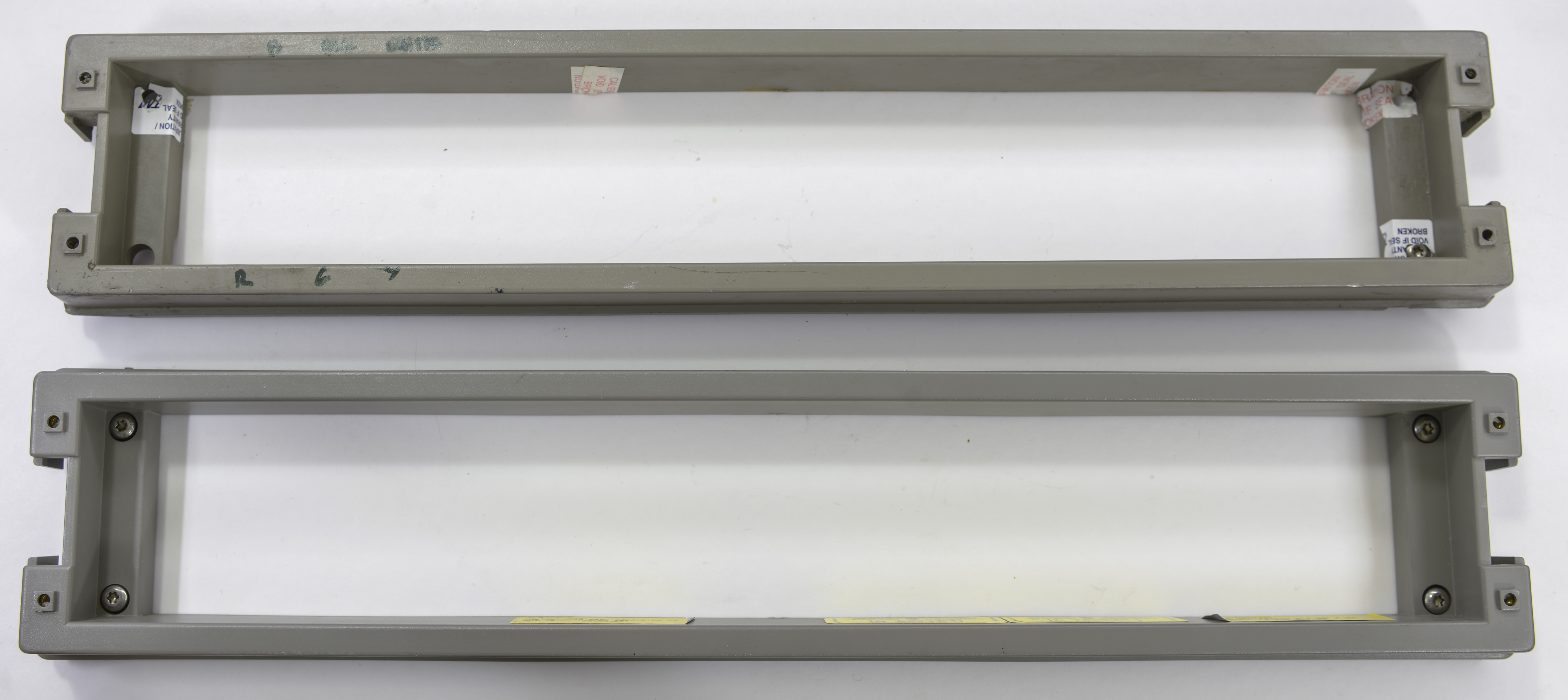
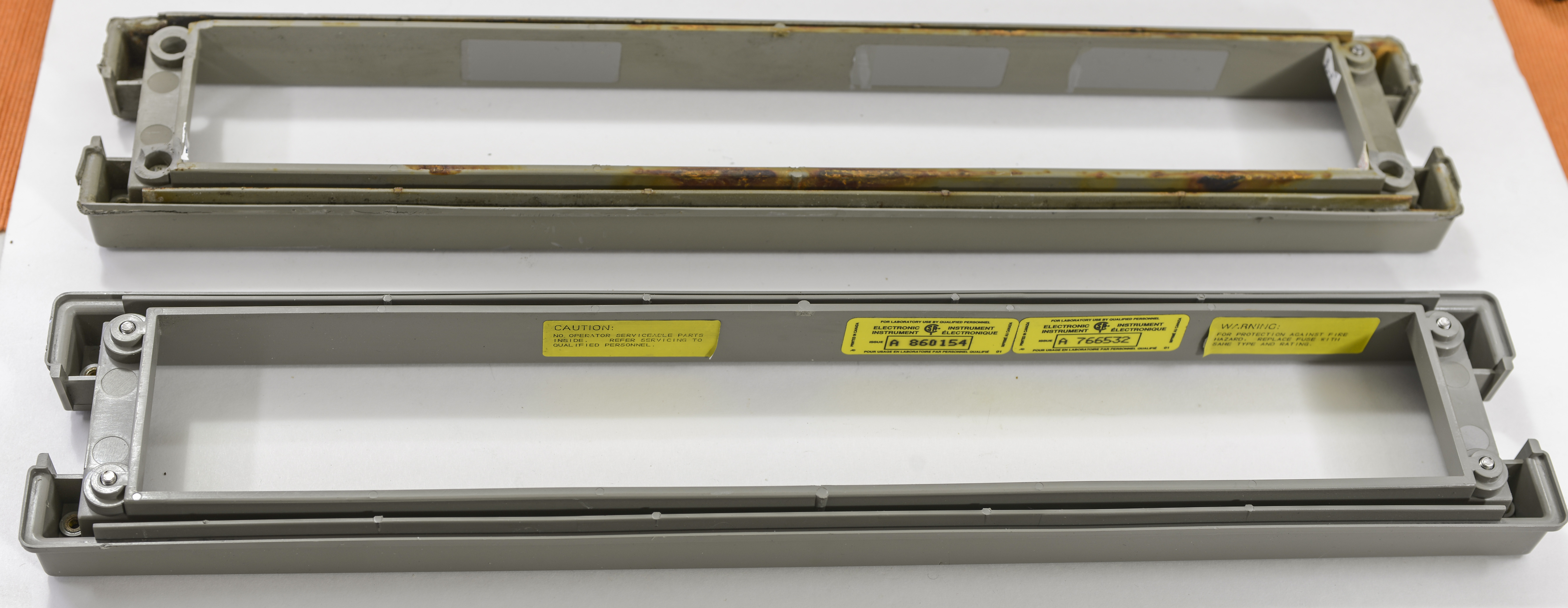
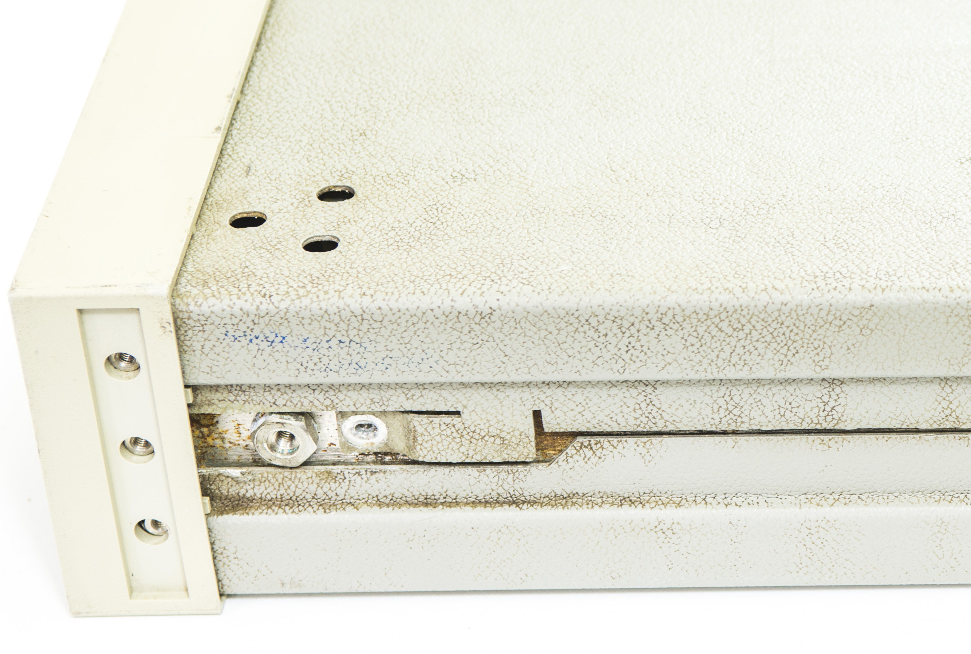
Original unit's bezel had three out of four screw mounts destroyed, so it was not holding well.

image

Stay tuned, to be continued... image

  • Sign in to reply
  • Cancel

Top Replies

  • tin_xdevs
    tin_xdevs over 9 years ago +2
    Alright, here's next update, for those who follow A5 board Replaced original rusty GPIB connector with fresh one from dead 33120A PCB, I had around. Funny traces are PCB spark-gaps for some ESD protection…
  • tin_xdevs
    tin_xdevs over 9 years ago +2
    Everything assembled now, and ready for initial testing.. Transformer data for comparisons: Voltage rail name Nominal spec Regulator Bad transformer in our unit New good transformer winding +18V +18VDC…
  • tin_xdevs
    tin_xdevs over 9 years ago +1
    Made an order on Digikey for fan, caps to recap A6 outguard power supply board (can call me paranoid, but I don't trust 20 year old electrolyte capacitors.). Only gotcha is that there was no axial type…
Parents
  • tin_xdevs
    tin_xdevs over 9 years ago

    Everything assembled now, and ready for initial testing..


    Transformer data for comparisons:


    Voltage rail name

    Nominal spec  Regulator  Bad transformer in our unit  New good transformer winding 
    +18V  +18VDC  U1, LM317T    Vmeas : 7.3 VAC, 0.5 Ω  Vmeas : 20.1VAC, 1.42 Ω
    -18V  -18VDC  U2, LM337T    Vmeas : 6.9 VAC, 0.5 Ω  Vmeas : 20.1VAC 1.42 Ω
    PSS   return for +-18VDC     Vmeas : 14.2 VAC, 1.0 Ω  Vmeas : 40.1VAC 2.88 Ω
    Resistance between ±18V winding and +5V    0.5 Ω  >10 GΩ 
    -18unreg     CR01-CR04 diode bridge       
    +5V  +5VDC  U3, UA7805    Vmeas : 7.0 VAC, 1.0 Ω  Vmeas : 9.1 VAC  
    -20V  -20VDC  CR17 zener + Pass PNP Q2      
    Resistance between ±18V winding and secondary shield    0.8 Ω Shorted!  >10 GΩ 
    Resistance between ±18V winding and secondary 5V shield  >10 GΩ  >10 GΩ 


    And this is how transformer made:

    image

    Assembly timelapse :


    You don't have permission to edit metadata of this video.
    Edit media
    x
    image
    Upload Preview
    image


    Front panel reports REQUIRED ACAL ALL, then quickly passing TEST RAM, TEST CHECKSUM and advances to TEST HARDWARE.
    After about 5 seconds unit have one short beep and error message ISOLATOR FAILURE. This meaning digital side cannot talk to digital side of inguard section via isolation interface.


    Here’s simplified block diagram of what interfacing look like:

    image


    If there is problem with either ASIC, it would be very hard to find replacement without buying new expensive boards. Let’s try troubleshoot issue on circuit level first, and hope for the best.

    Optical cables are simple plastic fiber, and pretty easy to check, since used receivers and trasmitter are using 660nm light, which is visible red.


    I can see red light on transmitter, and swapped cables without effect, having same error. When meter stuck on ISOLATOR FAILURE message it tries to send data, activating J102 Transmitter. If constant 660nm light directed on J101 receiver during meter power on, it resets itself in loop right after testing RAM, so likely that receiver path on A6 board is working.


    After some logic probing with my ancient Tektronix TLA714, I got idea that A5 is working okay, and problem narrow down to J102 transmitter interface


    image


    Signal path section on schematic of A6 PCBA:

    image

    One thing I notice before, LED light on J102 is really dim, could be also show actual problem with transmitter diode. Since it was easy, I actually swapped J102 with J303 before (which used for external triggering BNC ports), but result was same, so could be both transmitters are faulty.

    image

    To test this I had bypass transmit isolation path by adding a shorted between anode of A6 CR101 diode to U302 pin 9 input on A3 A/D board. Guess what, it booted and let me to UI.

    image image

    image image

    It does lit up ERR with next errors:


    202,“HARDWARE FAILURE — SLAVE TEST: CONVERGENCE”
    110,“CALIBRATION REQUIRED — ACAL”


    If I try run ACAL ALL, it says 205,“HARDWARE FAILURE — CAL VALUE OUT OF RANGE: 72” which is DCV A1 value, as per ALRM document.


    That's some progress, if you ask me.

    More to come, stay tuned...

    • Cancel
    • Vote Up +2 Vote Down
    • Sign in to reply
    • Cancel
Reply
  • tin_xdevs
    tin_xdevs over 9 years ago

    Everything assembled now, and ready for initial testing..


    Transformer data for comparisons:


    Voltage rail name

    Nominal spec  Regulator  Bad transformer in our unit  New good transformer winding 
    +18V  +18VDC  U1, LM317T    Vmeas : 7.3 VAC, 0.5 Ω  Vmeas : 20.1VAC, 1.42 Ω
    -18V  -18VDC  U2, LM337T    Vmeas : 6.9 VAC, 0.5 Ω  Vmeas : 20.1VAC 1.42 Ω
    PSS   return for +-18VDC     Vmeas : 14.2 VAC, 1.0 Ω  Vmeas : 40.1VAC 2.88 Ω
    Resistance between ±18V winding and +5V    0.5 Ω  >10 GΩ 
    -18unreg     CR01-CR04 diode bridge       
    +5V  +5VDC  U3, UA7805    Vmeas : 7.0 VAC, 1.0 Ω  Vmeas : 9.1 VAC  
    -20V  -20VDC  CR17 zener + Pass PNP Q2      
    Resistance between ±18V winding and secondary shield    0.8 Ω Shorted!  >10 GΩ 
    Resistance between ±18V winding and secondary 5V shield  >10 GΩ  >10 GΩ 


    And this is how transformer made:

    image

    Assembly timelapse :


    You don't have permission to edit metadata of this video.
    Edit media
    x
    image
    Upload Preview
    image


    Front panel reports REQUIRED ACAL ALL, then quickly passing TEST RAM, TEST CHECKSUM and advances to TEST HARDWARE.
    After about 5 seconds unit have one short beep and error message ISOLATOR FAILURE. This meaning digital side cannot talk to digital side of inguard section via isolation interface.


    Here’s simplified block diagram of what interfacing look like:

    image


    If there is problem with either ASIC, it would be very hard to find replacement without buying new expensive boards. Let’s try troubleshoot issue on circuit level first, and hope for the best.

    Optical cables are simple plastic fiber, and pretty easy to check, since used receivers and trasmitter are using 660nm light, which is visible red.


    I can see red light on transmitter, and swapped cables without effect, having same error. When meter stuck on ISOLATOR FAILURE message it tries to send data, activating J102 Transmitter. If constant 660nm light directed on J101 receiver during meter power on, it resets itself in loop right after testing RAM, so likely that receiver path on A6 board is working.


    After some logic probing with my ancient Tektronix TLA714, I got idea that A5 is working okay, and problem narrow down to J102 transmitter interface


    image


    Signal path section on schematic of A6 PCBA:

    image

    One thing I notice before, LED light on J102 is really dim, could be also show actual problem with transmitter diode. Since it was easy, I actually swapped J102 with J303 before (which used for external triggering BNC ports), but result was same, so could be both transmitters are faulty.

    image

    To test this I had bypass transmit isolation path by adding a shorted between anode of A6 CR101 diode to U302 pin 9 input on A3 A/D board. Guess what, it booted and let me to UI.

    image image

    image image

    It does lit up ERR with next errors:


    202,“HARDWARE FAILURE — SLAVE TEST: CONVERGENCE”
    110,“CALIBRATION REQUIRED — ACAL”


    If I try run ACAL ALL, it says 205,“HARDWARE FAILURE — CAL VALUE OUT OF RANGE: 72” which is DCV A1 value, as per ALRM document.


    That's some progress, if you ask me.

    More to come, stay tuned...

    • Cancel
    • Vote Up +2 Vote Down
    • Sign in to reply
    • Cancel
Children
  • Robert Peter Oakes
    Robert Peter Oakes over 9 years ago in reply to tin_xdevs

    Very impressive work so far, keep it up, im rooting for you to crack this thing

    peter

    • Cancel
    • Vote Up 0 Vote Down
    • Sign in to reply
    • Cancel
  • jw0752
    jw0752 over 9 years ago in reply to tin_xdevs

    Hi Illya,

    This is better than a good mystery novel. I am eagerly awaiting the next chapter.

    John

    • Cancel
    • Vote Up +1 Vote Down
    • Sign in to reply
    • Cancel
element14 Community

element14 is the first online community specifically for engineers. Connect with your peers and get expert answers to your questions.

  • Members
  • Learn
  • Technologies
  • Challenges & Projects
  • Products
  • Store
  • About Us
  • Feedback & Support
  • FAQs
  • Terms of Use
  • Privacy Policy
  • Legal and Copyright Notices
  • Sitemap
  • Cookies

An Avnet Company © 2025 Premier Farnell Limited. All Rights Reserved.

Premier Farnell Ltd, registered in England and Wales (no 00876412), registered office: Farnell House, Forge Lane, Leeds LS12 2NE.

ICP 备案号 10220084.

Follow element14

  • X
  • Facebook
  • linkedin
  • YouTube