


goal: make a programmable lab switch, that can switch a set of signals or supplies on or off
- can be used in an automated process, with other lab instruments
- may be used to switch power on/off, simulate a button click, switch an audio input on/off, ...
- simple: you can control IO pins, that can drive a relay, FET, or any other switching element that can be controlled with a generic 3.3V GPIO.
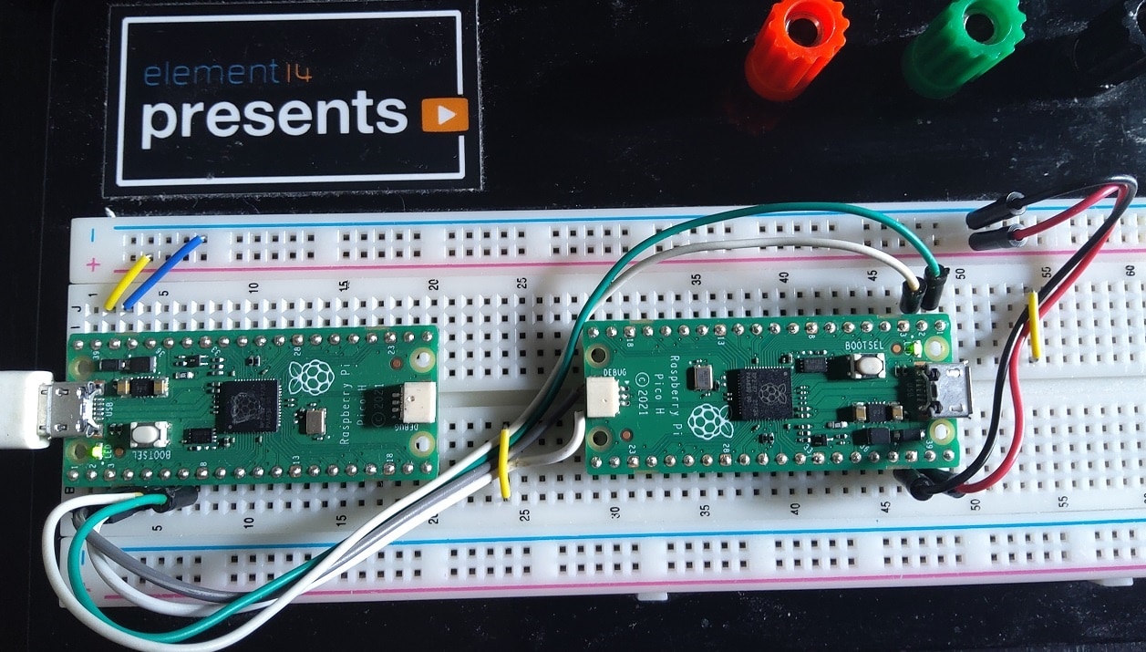
reality: It 'll be a Pico with relais attached, and you control these over its USB port.
I've made several designs earlier, that use the patterns for this project:
- SCPI library to turn user commands into to GPIO output pin state changes (yes: just on/of
 )
) - UART handling in FreeRTOS, with interrupt support
- FreeRTOS concepts like: messaging, queues, semaphore, tasks
SCPI commands and matching LabVIEW driver will be compatible with a similar project I made for the Pi Propper.
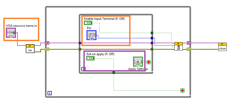
A typical command would look like this::DIGITAL:OUTPUT0 ON
A LabVIEW flow:
real goal: it 'll be a showcase for using FreeRTOS with the PICO-PI in a real-world application. I've been testing out the multi-core version of the RTOS on the Pico lately, and this is a practical use case.
little bonus: It 'll run on FreeRTOS standard, and on the multi-core FreeRTOS SMP. On SMP, it 'll use both RP2040 cores.
If you have a Pico (or other RP2040 board), you can play along. No additional hardware required (the on-board LED will do) , and you can use a simple terminal (PuTTY, ...) or Python instead of LabVIEW.
I've attached the project skeleton to this post. It's a FreeRTOS blinky (already adapted for this project), a good way to check if you can successfully build a project for the Pico C SDK and the FreeRTOS port. That's the only assumption I make at the start of this series.


