Table of Contents
Introduction
While working on a GPS project Fun With Arduino, Global Navigation Satellite Systems (GNSS) and Teseo III it got me thinking about how dependent we are on that technology, and how on earth people managed in the past. This blog post documents my findings.
Longitude and Time-keeping
In the introduction of a book called Longitude, Neil Armstrong mentions how Pope Alexander IV drew a vertical line from North to South, and assigned all lands to the two top maritime powers of Europe: all lands to the west to Spain, and all to the right to Portugal. The problem was, no-one knew where the line fell!
The problem of identifying precise longitude was of high importance, because sailors would routinely perish, because of the difficulty of determining where land was.
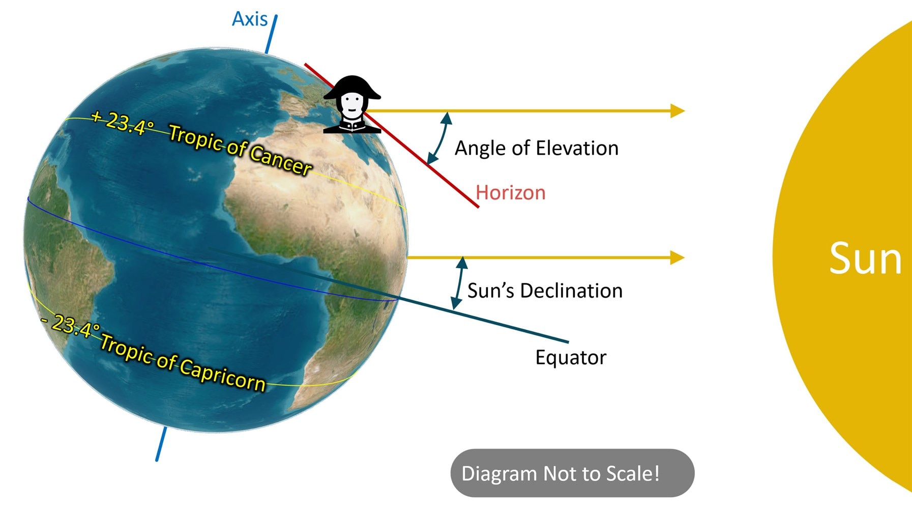
Latitude (how far up or down the globe) was not too difficult to figure out, because it could be determined in several ways; by the season and length of the day, or measuring the angle of the sun, or you could search for particular stars (for instance the North Star) and measure its angle to the horizon. In brief, a quick way would be to measure the angle of the sun from your visible horizon, and subtract it from 90. Then, a correction is needed because the earth tilts up to plus or minus 23.4 degrees over the course of the year; it's seasonal (about +23.4 degrees in mid-June, and -23.4 degrees in mid-December, and is close to zero mid-March and mid-September), is easy to calculate, and is called the sun's angle of declination. You'd need to subtract the magnitude of the sun's angle of declination (Python example code to calculate it), to get an accurate result.
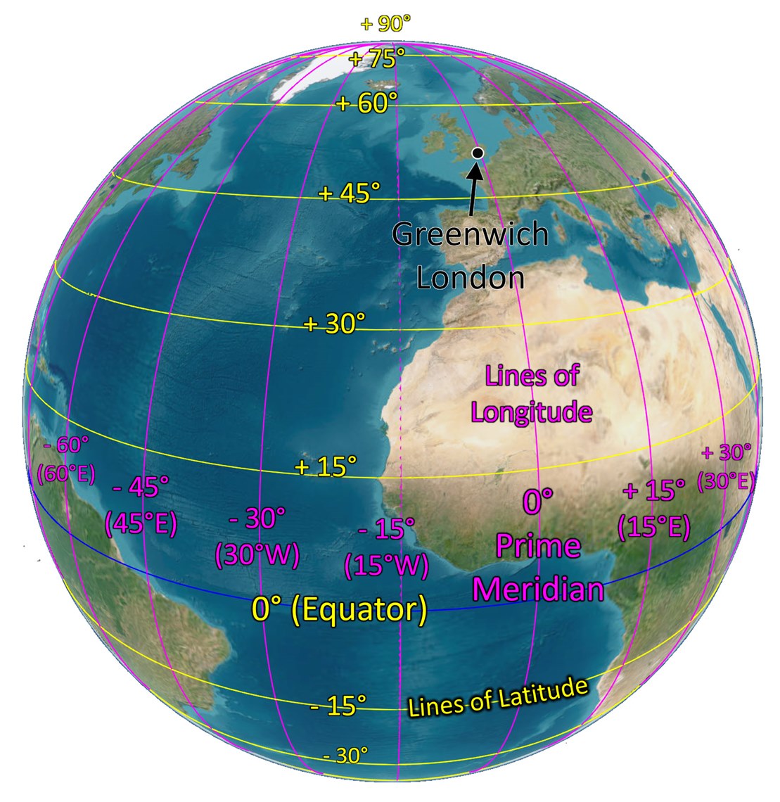
However, longitude starts at an arbitrary man-made position (it happens to be in Greenwich, London). There are many stories of ships traveling the wrong distance east or west around the globe, and (if not crashing into rocks), poor longitude estimates resulted in overshooting or undershooting land, and, with depleting food, and risk of scurvy, the captain deciding to turn around, and traveling for days or weeks, only to then realize that the first direction must have been correct. Just on one voyage, two thousand sailors on four warships died for want of better navigation, and eventually, the UK government issued a reward (worth millions in today’s money) for a solution. It went unclaimed for more than half a century.
Some people believed the solution lay with correct timing. The problem was, clocks were inaccurate in the 1700’s!
The reason time is important, is that, (there are several ways, but this is the simplest to understand) by simply looking at the position of the sun (which moves across the sky at 15 degrees per hour), and knowing the time at the Greenwich Meridian, you can determine your longitude. For example, if the sun is directly above you, and the time at Greenwich is 1 pm, then you know that your longitude must be 15 degrees west of Greenwich.
There were some crackpot suggestions for the time problem, one of them being ‘the wounded dog’ method. There was a theory that a particular medicine had mystical powers of ‘healing at a distance’ if the original bandage was soaked in it. The logic went that if a dog were deliberately wounded and then placed on a ship, then someone on land could daily soak the bandage at noon, and the distant wounded dog would let out a yelp at that precise time since the medicine would sting in the wound. You’d just need to deliberately prevent the wound from fully healing, for months while out to voyage.
The person who actually solved the problem, John Harrison, was treated badly, and, for a lifetime’s work, received just a small reward with only three years of life left to enjoy it. John Harrison’s solution was an ultra-accurate timepiece (so accurate, it easily competes with modern quartz watches some 250 years later!) that could withstand operation on ships.
Hyperbolic Radio Navigation
Fast-forward to the period approaching World War 2, and now there were requirements for accurate airborne navigation. Various radio-based ideas were considered, and it was soon very obvious that relying simply on signal strength was not very feasible because it was hard to accurately measure signal strength at a distance because it dropped off so quickly, and therefore the inaccuracies would be significant.
It was felt by some that pulse-based (RADAR was a secret at that time) or phase-based systems might hold more promise.
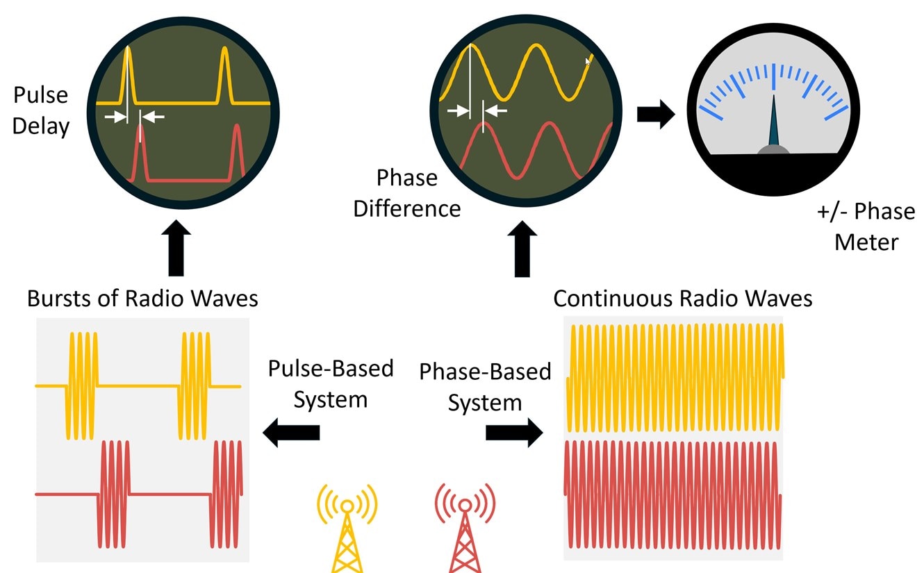
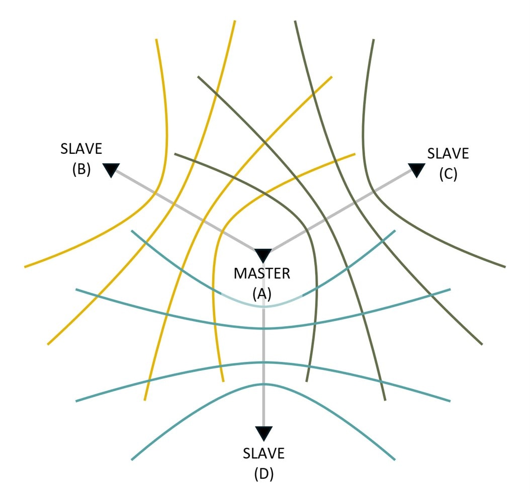
This opened up a whole range of possibilities, collectively known as hyperbolic navigation systems. If you have two transmitters transmitting in phase, or transmitting pulses simultaneously, then if a receiver is exactly halfway between the two transmitters, then the signals arrive in phase (or pulses arrive simultaneously). If, however, the receiver is at a different location, then there will be a phase or delay difference. The difference remains the same if the receiver is at any location which traces a hyperbola. The diagram below shows why.
The concentric circles emanating from one transmitter site indicate the positions where signals arrive at fixed times. If you try to intersect those circles with those from the other transmitter location, such that the difference between the pairs of ranges always remains a fixed distance, then hyperbolae are traced out. All the hyperbolae in the diagram below, have the same fixed difference of phase or pulse, the colors are just to identify separate lines or ‘lanes’, but if the receiver is on any of these lines, the phase difference is the same. For any given delay or phase difference, it is possible to plot a set of hyperbolae.
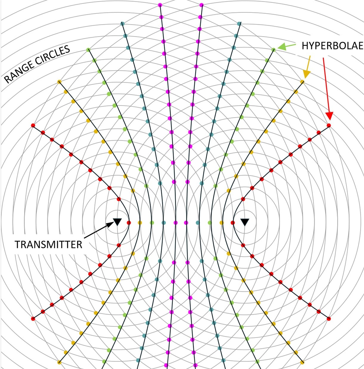
What the above means is that if you have a way of measuring the phase difference or pulse arrival delay between the two transmitters, you can place yourself on a set of hyperbolae. You won’t know which of the hyperbola lines you are on, however.
Various things can be done to try to identify the particular hyperbola out of the set. One method is for the two transmitters to sweep through phase relative to each other. That results in the hyperbola lines bending as the phase changes so that the receiver sees a time-varying signal strength, an increase in received signal when they are on a hyperbola, and a decrease when they are in between two lines. Then, timing can help identify which hyperbola you’re on. Another method is to switch to a lower frequency, so that there are fewer hyperbola lines temporarily, so that the receiver can coarsely resolve, before switching to a higher frequency.
Pulses: Gee System (QH)
One system developed in the UK, later called the Gee system (known as ‘QH’ during WW2), relied on pulses. A master transmitter would synchronize three slave transmitters, all transmitting a pulse at the same frequency after a fixed pause from the master transmission. Together, these four transmitters are known as a chain.
At the receiver end, the pulses were observed on a simple oscilloscope that didn’t have trigger circuitry. The circuitry would direct the pulses onto two traces. The master transmitter pulse was observed on both traces. The next received pulse would be sent to the top trace. The pulse after that was sent to the second trace. The final pulse was sent to both traces, but it happened to be a double pulse, so it could be distinguished. The operator would measure the distance between the pulses, and the intersecting hyperbolae would provide a position fix.
The photo here shows a Gee receiver and display unit.
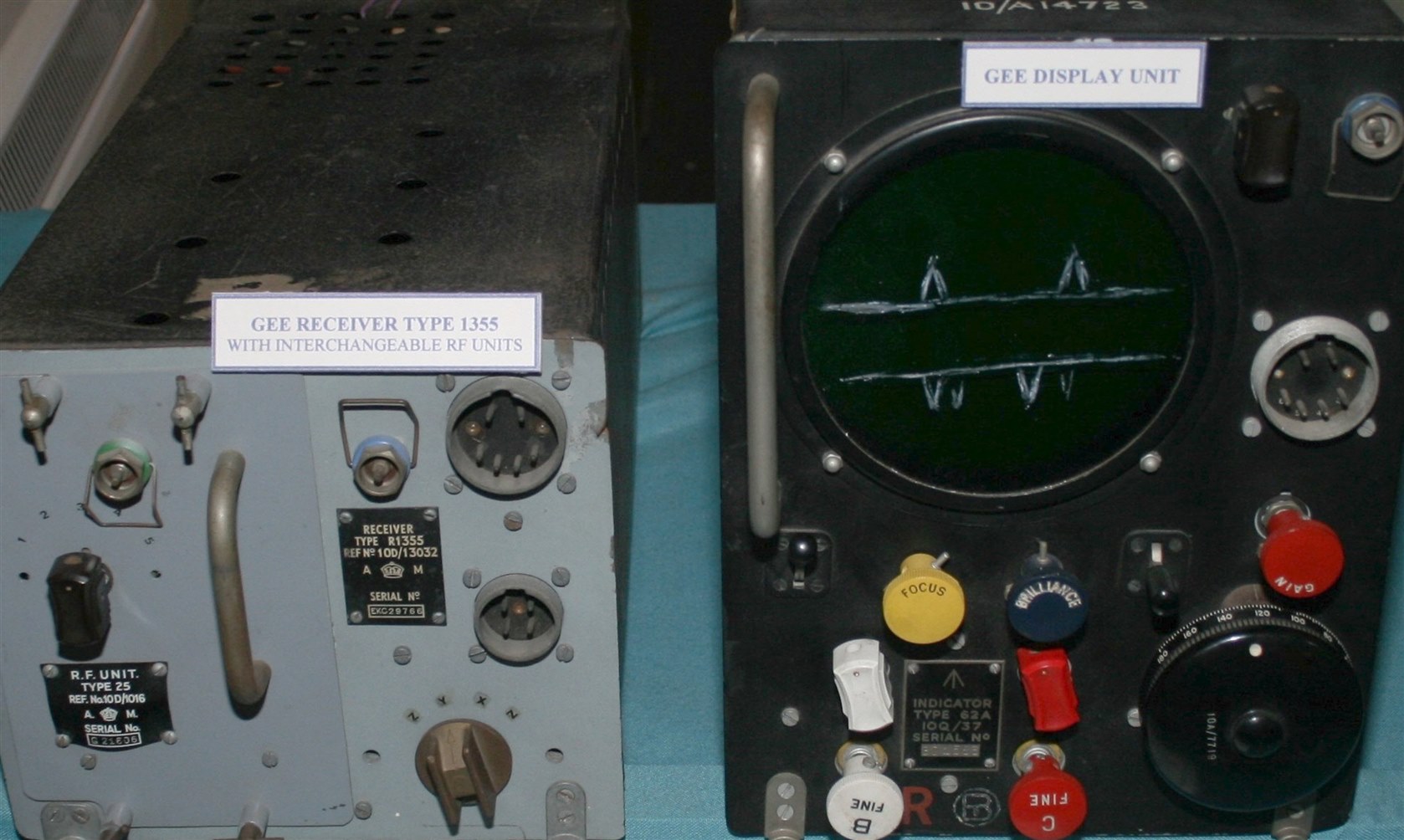
Image source: Wikipedia
There is some excellent detail (including beautiful photographs) at radiomuseum.co.uk.
Since there was no trigger circuitry, the operator manually fine-tuned until the pulses sat in the correct position on the display. Best-case accuracy was about 150 meters, but at distances of several hundred miles, the error could easily be several miles.
Gee was used during WW2 for navigation around the UK.
Phase: Decca Navigation (QM)
For Operation Overlord (Battle of Normandy), a different navigation system was used, called QM (later called the Decca Navigational System). The idea was invented by William O’Brien and Harvey Schwarz in the USA but gained significant interest in the UK and was trialed in 1941 on the Welsh coast. The system relied on phase difference, rather than measuring the time between pulses. The way it worked was that a master site and a number of slaves (two or three), together known as a chain, all transmitted signals at different frequencies, but all locked to a base frequency. The receiver would multiply pairs of received signals, to a common frequency, and then work out the phase difference.
In 1943, the base frequency f was 14 kHz, and the master and two slaves transmitted at 6f, 8f and 9f respectively (i.e. 84, 112 and 126 kHz).
At the receiving end, the master and first slave received signals would be separately multiplied by 4 and 3 respectively, i.e. 84 x 4 and 112 x 3, which would result in two signals both of frequency 24f (336 kHz), but with different phase, depending on location with respect to the master and the first slave.
Similarly, the master and second slave signals would be separately multiplied by 3 and 2, resulting in two signals of frequency 18f (252 kHz), again with a phase relationship. (Later, a third slave was added, at a frequency of 5f).
Just as shown in the earlier diagram, hyperbola lines could be drawn at any phase relationship, for instance when the signals are in phase, at zero degrees.
The lines were used as ‘lanes’ during Operation Overlord, creating invisible paths through the English Channel towards Normandy. Minesweepers followed those paths, allowing ships and landing craft to follow.
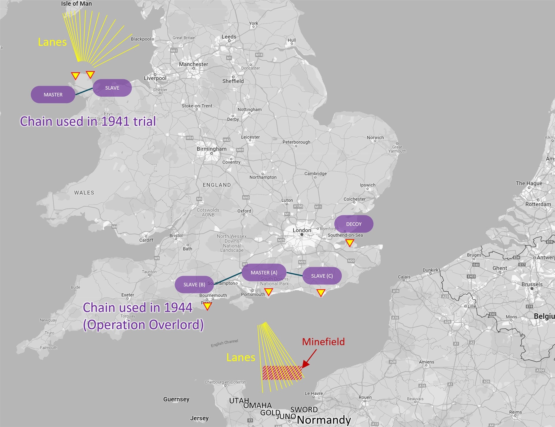
The receiver didn’t use an oscilloscope but instead used a center-zero meter that would display the phase shift. The lanes were separated by several hundred meters. A tiny movement (a few feet) off one of the lanes would cause a phase shift from zero, which would move the meter needle significantly. By seeing the number of deflections, the lines could be easily counted. After WW2, further improvements to the system were made, so that lane counting became unnecessary. By the time the system was fully mature, the transmitter sites were transmitting signals at different frequencies, over a 20-second period, repeatedly, and the sequence was quite complex. A very good collection of information about the Decca system can be found at Jerry Proc’s website.
By the 1980’s or so, there were about 50 chains deployed. The diagram below shows the European chains; 25 were deployed there. The circled values are unique chain numbers. The slave transmitters within each chain had color-code identifiers (red, green, purple).
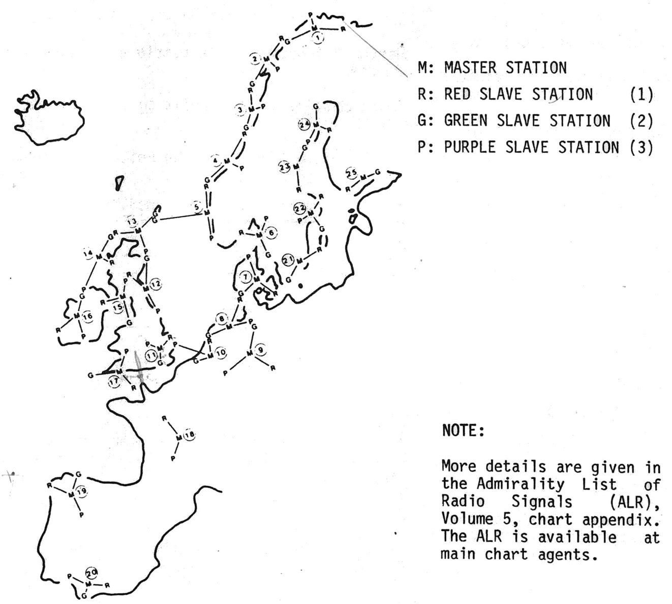
Image source: Philips
Decca Yacht Navigator Teardown
The Decca system was deployed in many regions, and was used commercially until about the year 2000. The receivers were made by Racal Decca, but eventually other manufacturers, particularly Philips, built them too. I found a low-cost Decca Yacht Navigator Mk III on eBay, and I was curious to explore it a bit. This model is made by Philips, despite the Racal logo.
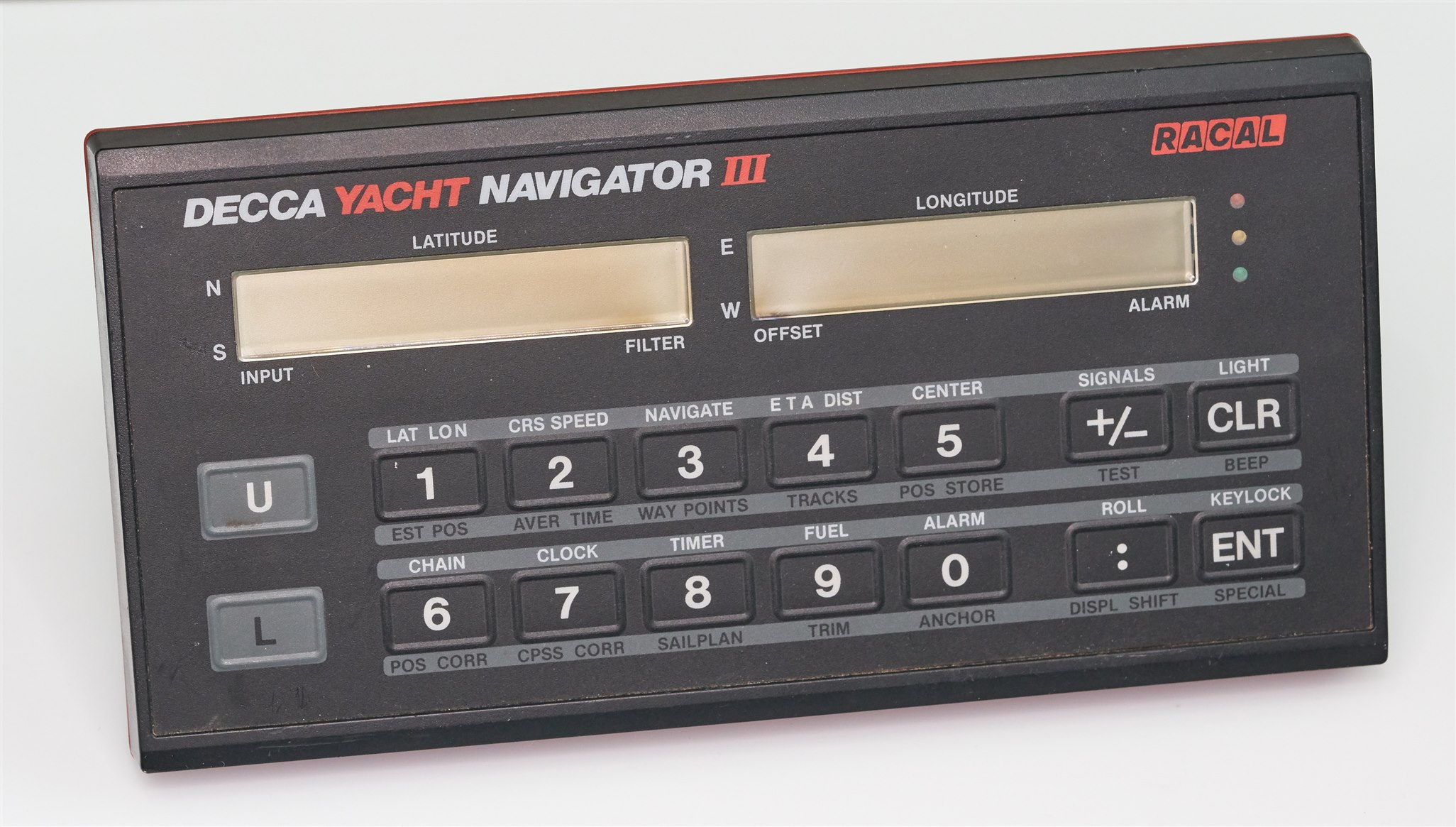
I’ve scanned the user manual, and uploaded it to the ElektroTanya website (the search term on the website is ‘decca yacht’).
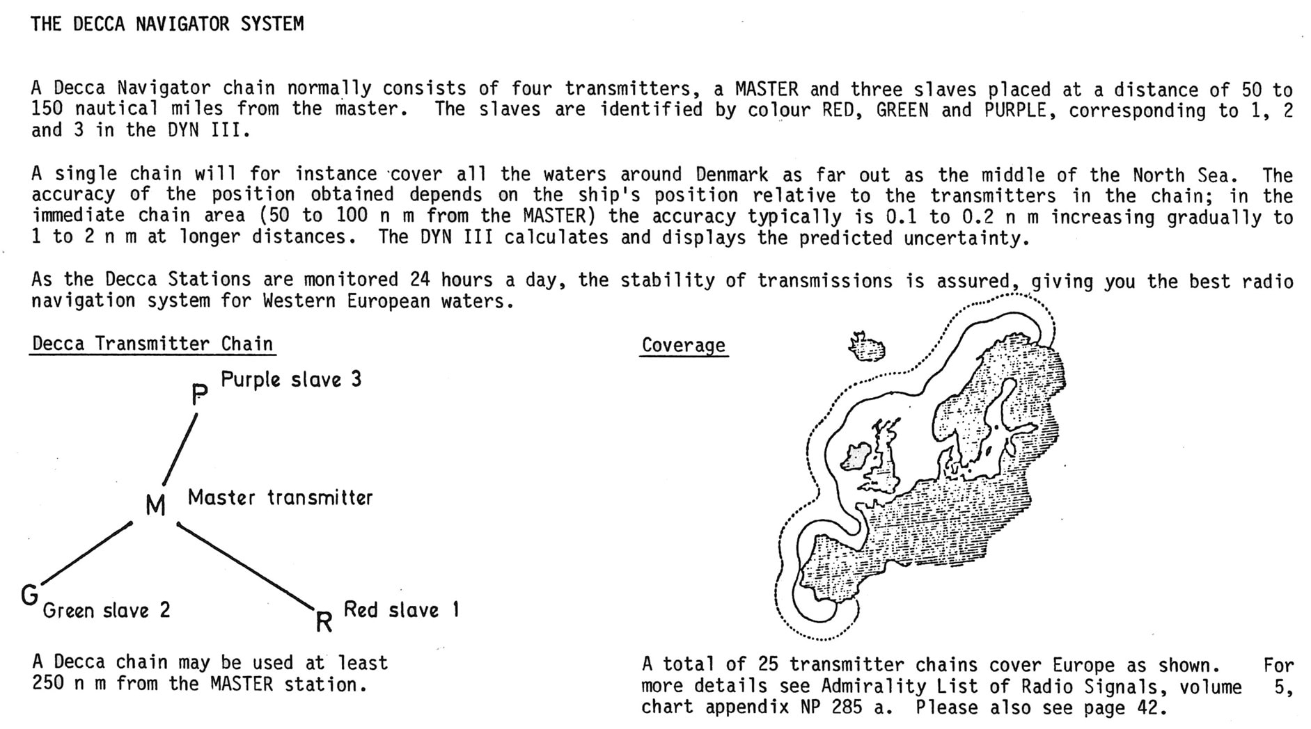
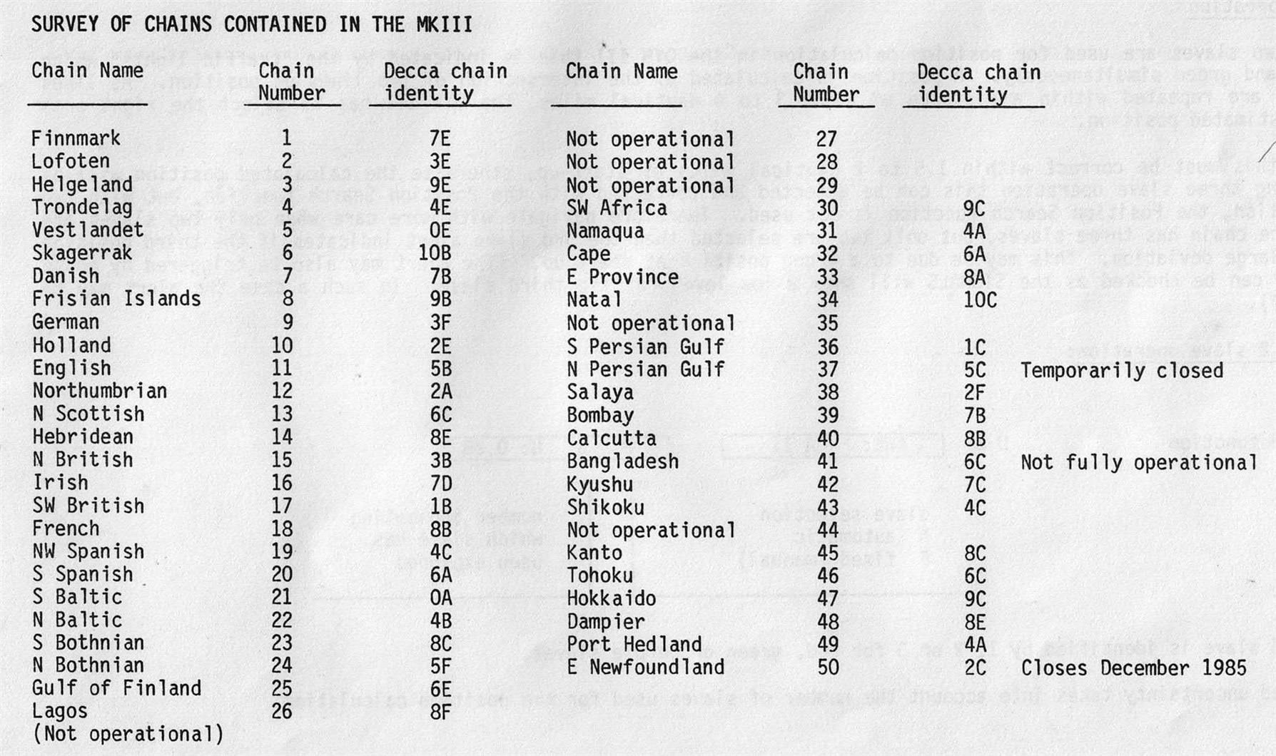
The user manual contains the following hardware block diagram; you can see that there are two receivers, one at the 6f (master) frequency, and the other at the 8f (slave) frequency. However, I’m not sure why the diagram does not mention the 9f and 5f frequencies for the other slave transmitters. Perhaps the box labeled 8f can be tuned to the other frequencies.

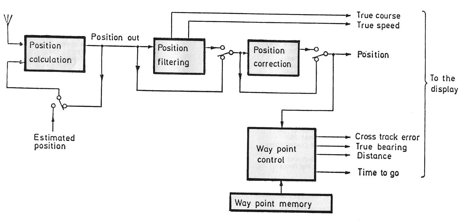
There’s also a software block diagram, although that doesn’t reveal as much as I’d like either:
The Yacht Navigator is easy to install; at a minimum it requires 12V supply connections, and an antenna. Optionally, an external serial-controlled secondary display can be attached.
The contents of the two halves of the case are shown below. The lower half has all the interesting bits. Almost everything looks in excellent condition, due to the coating on the board. One of the IC sockets has a small amount of corrosion. The socket for the keypad’s flexible sheet ribbon is very badly corroded. The NiCd battery needs replacement too (not that there’s any benefit to doing so, since the Decca transmitters ceased operation almost 25 years ago). The battery has leaked and caused some damage to traces I believe.
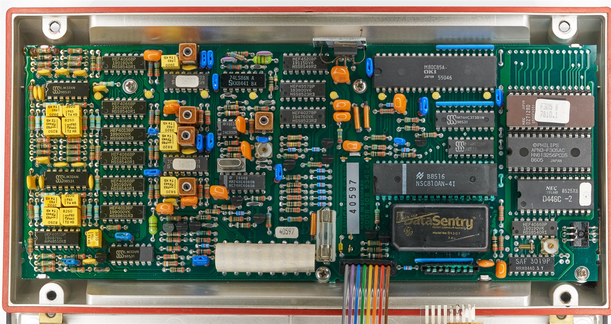
The top half of the enclosure houses a PCB containing two LCD screens and drivers for them, plus a piezo beeper. The touchpad keyboard is not accessible without peeling off the front panel, which I didn’t do.
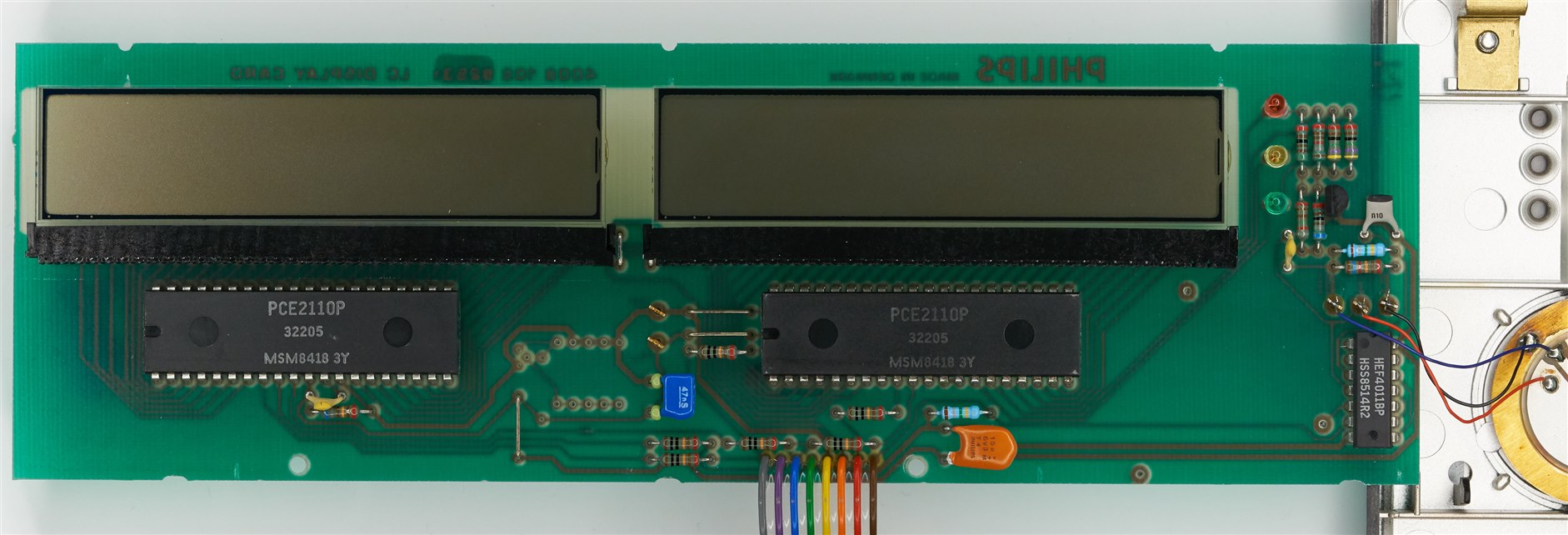
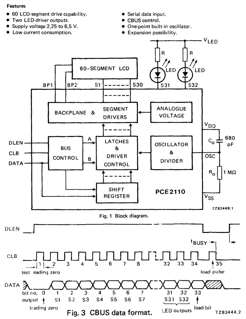
The LCD driver uses an old simple serial interface called CBUS, which is very SPI-like.
Back to the main board, here is an annotated view of it:
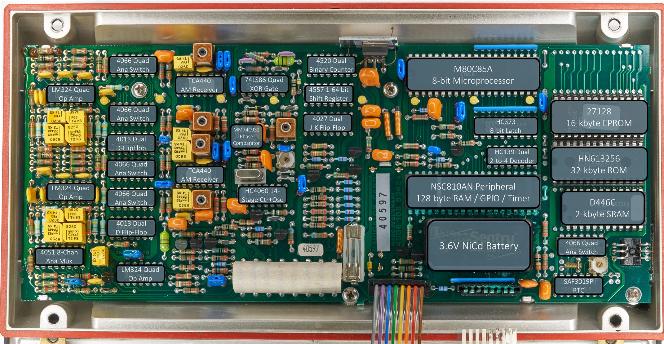
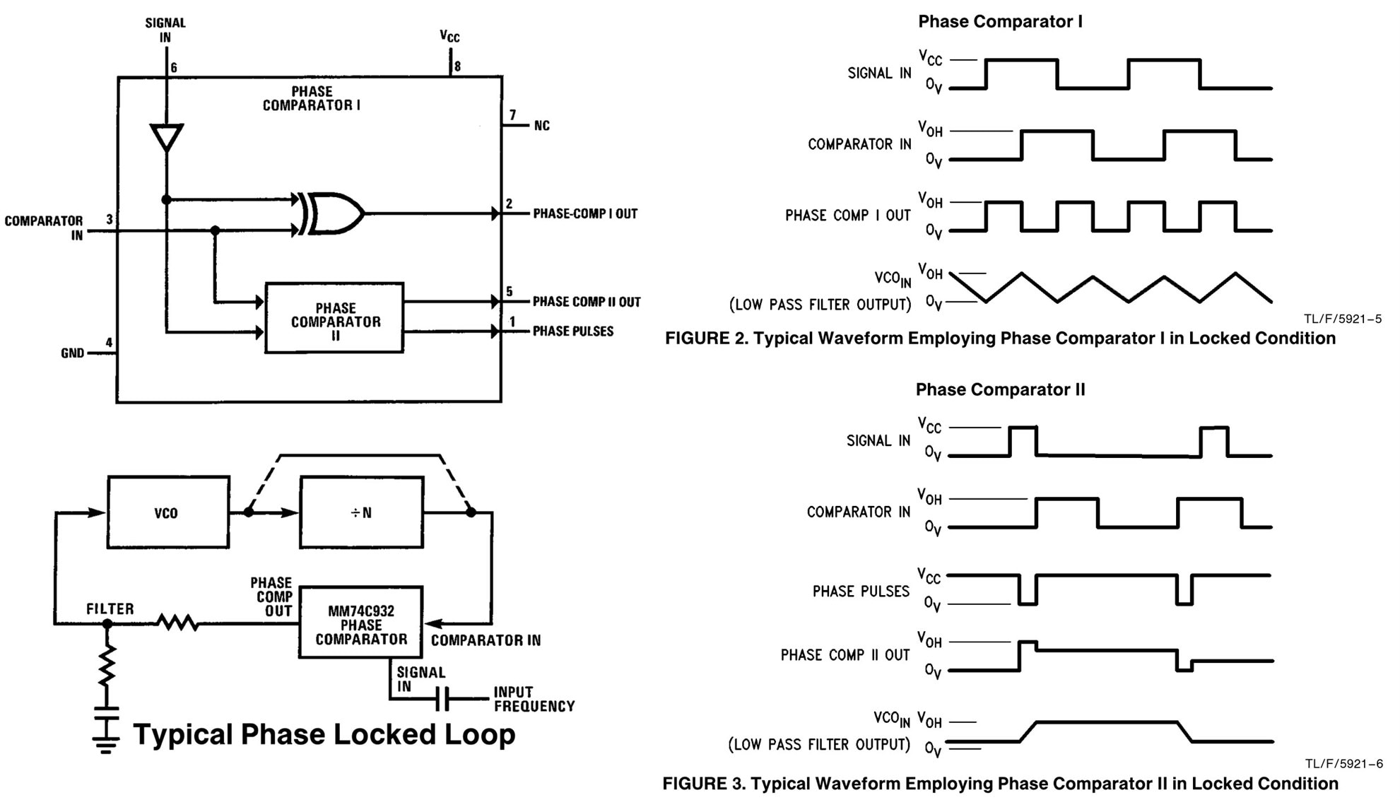
There are quite a few interesting parts on it! There’s lots of CMOS logic. The main crystal (5.24288 MHz) oscillator is at the center of the board. I’m guessing the parts at the center of the board form a frequency synthesizer, but I have no idea, and I couldn’t find a circuit diagram. The MM74C932 DIP-8 chip above the crystal is a phase comparator IC.
There are two TCA440 RF receiver ICs. One is likely used for the master signal, and the other for one of the slaves, i.e. different slave reception may be sequential.

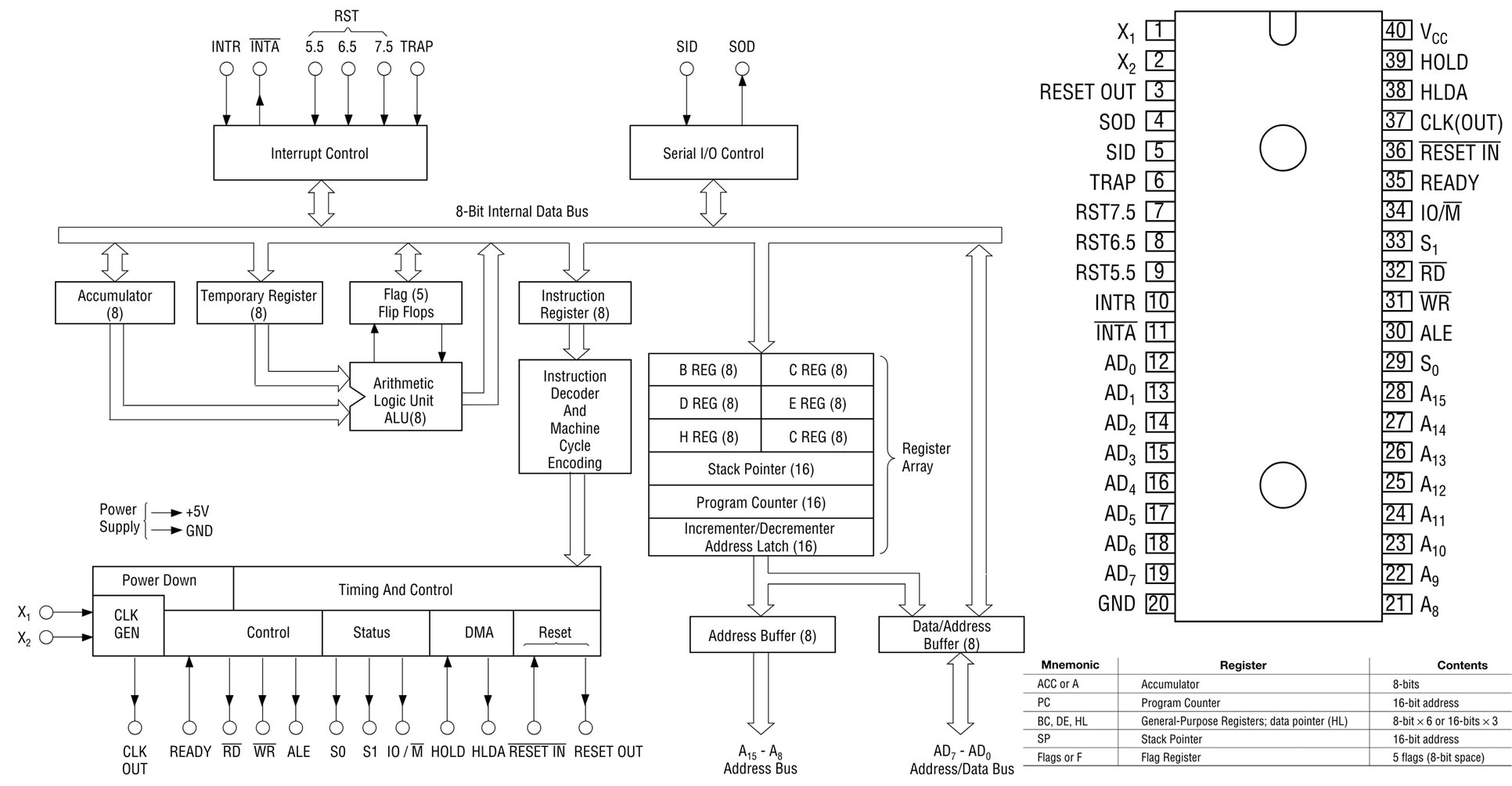
The M80C85A chip at the top-right of the board is an 8085 microprocessor.
Interestingly, there is both an EPROM (27128) and a mask ROM (HN613256) on the board. I’m guessing the mask ROM contains tables chain data, such as locations, chain IDs, and frequencies, and the EPROM contains the firmware. Both the EPROM and ROM are in sockets, so I removed them and read out the information (if you’re curious what’s in there, the files are uploaded to the Elektrotanya website, search for ‘decca yacht’).
There are not many text strings (the 7-segment LCD digits only show numbers), but there was some text at the end of the EPROM.

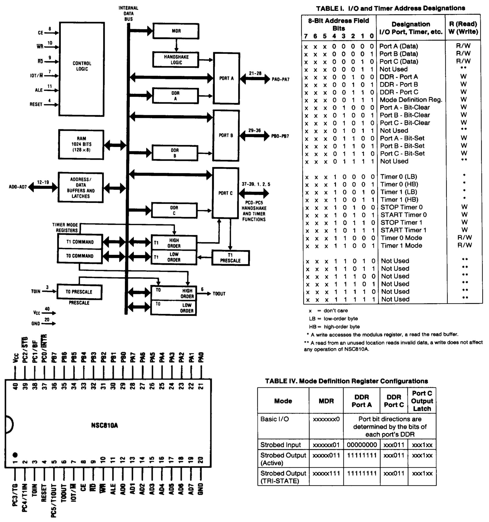
The NSC810AN chip contains several useful peripherals for a computer system.
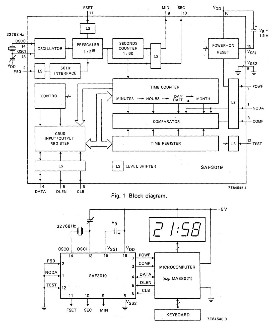
The lower right of the board contains the real-time clock chip (SAF3019) and a 32.768 kHz crystal.
Summary
It’s easy to take satellite-based navigation systems for granted these days, but there was a time when thousands of lives would frequently be lost due to the difficulty of determining longitude. Although that was solved in the 18th century, there were new demands during WW2.
Prior to GPS deployment, hyperbolic navigation systems were the state-of-the-art, a couple of them being QH and QM, or Gee and Decca, respectively. The Decca system relied on phase measurement to place the receiver on hyperbolic lines or lanes and, with multiple transmitters, onto a grid of lanes. After WW2, the system was adapted for commercial use and ran successfully until the year 2000. An example of a Decca navigation system receiver was examined briefly.
If you found that interesting, then it may be worth assembling a GPS module, and exploring what you can do with it.
Thanks for reading.
Further Reading
Longitude book by Dava Sobel
Decca Yacht Navigator User Manual
Early History of the Decca Navigation System - Powell
Decca website by Jerry Proc


Top Comments
-

genebren
-
Cancel
-
Vote Up
+1
Vote Down
-
-
Sign in to reply
-
More
-
Cancel
Comment-

genebren
-
Cancel
-
Vote Up
+1
Vote Down
-
-
Sign in to reply
-
More
-
Cancel
Children