Introduction
This blog post is about RF SMA connectors that, as the title suggests, are not soldered onto circuit boards; they are screw-fit!

I wish I had known about these connectors when I built up a component analyzer testbed (photo further below in the blog). That project uses about 18 SMA sockets alone, and parts of the design (particularly the component fixture) are difficult to swap out to try out improvements or replace component fixtures without throwing away expensive SMA connectors.
I left off at the last blog waiting for some printed circuit boards to turn up so that I could see if the PCB footprints Jan Cumps and I had collaborated on were any good! Well, the boards did turn up, twice! The first batch was a mistake (my mistake, not the PCB manufacturer's); I forgot to specify ENIG PCB finish. The finish is important because the RF properties of the traces get affected negatively with the cheaper HASL finish.
This blog post discusses how I tested the solderless SMA connectors with the two test boards and shows the results.
SMA Connector and Microstrip Testbed
The point of the PCBs was to try to figure out what footprint dimensions and trace widths would provide the desired 50-ohm characteristic impedance, because that’s what is needed to successfully deliver signals from coax, through the connector, onto the PCB, and into whichever component the trace is connected to. If the impedance differs at any point, then a bit of signal reflection will occur, causing signal distortion as well as power loss.
To do the test, I used a simple scalar method, known as a transmission or S21 measurement (the number refers to the port numbering on vector network analyzers). A vector measurement would be better, but that requires an expensive kit (known as an Open/Short/Load [OSL] SMA calibration kit) that is necessary to calibrate out interconnecting cables between the test instrument and the board. Without that kit, reasonable results are not possible beyond say 100 MHz, and unfortunately, it costs 4-digit sums, although there is a low-cost option at about $500 that I might buy one day. There are very low-cost calibration kits on eBay, but without a set of parameters/coefficients, they are not helpful unless one has a way to determine those values (there are some non-trivial methods but at some point, it may just be worth paying the $500).

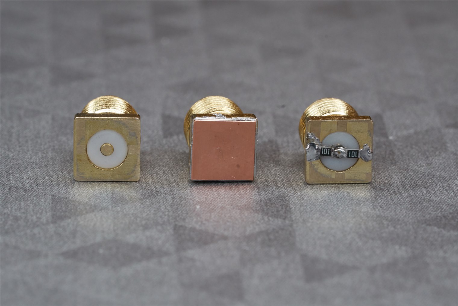
The photo above shows a homemade calibration kit (from left to right, it consists of the open, short, and load elements), but it is useless until its parameters can be determined. The instrument I am using doesn’t support a vector S21 measurement anyway (it would be possible to do a vector S11 measurement, but it still requires a known SMA calibration kit). The particular test I did can be performed with any spectrum analyzer along with a signal generator (for instance a tracking generator would be ideal).
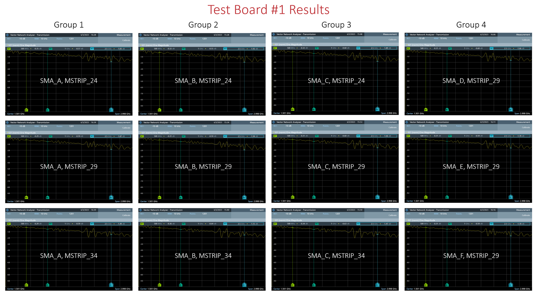
For the S21 test, I connected two SMA cables to a Rohde and Schwarz FPC1500 Vector Network Analyzer, and then joined the two cable ends together with a back-to-back SMA female adapter, so that I could normalize the measurements since the signal generator inside the instrument won’t have a perfectly equal power output at all frequencies. Once the normalization was done, I removed the adapter and then inserted test board #1 in its place and recorded the results! I repeated this for each test scenario that was on the test board (there are twelve scenarios, in four groups of three). To understand the differences between each of the twelve scenarios, please refer to the first blog.

Results
The results below (click the image to enlarge, because the traces are a little faint to see otherwise) show that none are optimal since this was just a first trial-and-error iteration, but generally, the best result was for scenario SMA_A+MSTRIP_29, which is in group 1. Up to around 1.3 GHz, the transmission loss for this scenario had the least ripple, and loss was less than 1 dB, i.e. about 20% power loss, up to around 1.3 GHz. At 3 GHz (the limit of the measurement) the loss was just under 2 dB, i.e. a third of the power was lost. This was for test board #1, which has long traces.

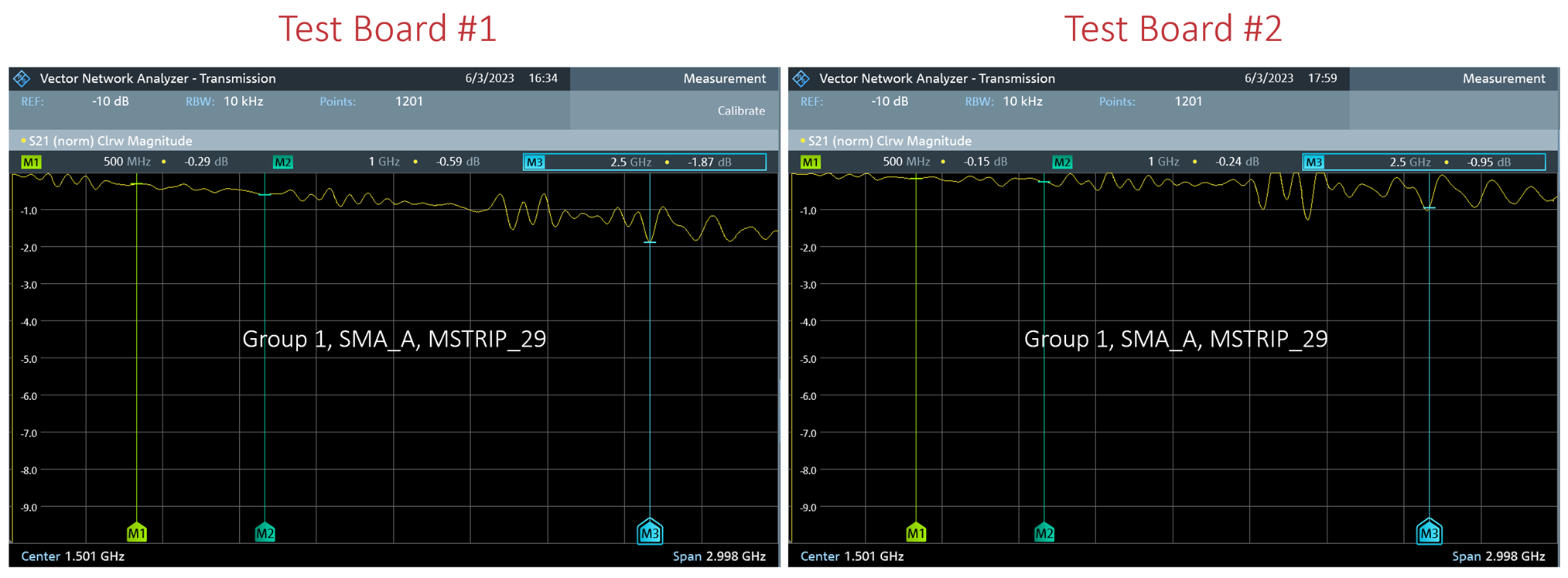
I also tried test board #2 (which has shorter traces) for the best scenario from board #1, and the results from both boards are shown side-by-side below. The loss up to 1.3 GHz was less than 0.5 dB, i.e. 10% loss. In other words, for a single SMA connector, plus a short (perhaps more realistic in a real circuit) transmission line, then the loss up to 1.3 GHz is 0.25 dB, i.e. 5% loss worst case.

The results also show the importance of actually having a decent simulation or engineering assistance from SV Micro, because otherwise a significant amount of time would be expended, along with the right test tools, to improve these values further.
Still, there are plenty of use cases for SMA connectors on FR4 board at lower frequencies up to 1 GHz or so! In fact, my use-case only requires operation just up to 50 MHz.
I have a (really nice) DIY VNA, which was built from a published design originally in RSGB’s RadCom magazine. It makes an excellent impedance analyzer for components, as good as any typical commercial device, maybe better! but it requires a test fixture. So far I have been using traditional SMA connectors but that is limiting because I need to keep buying new connectors each time the test fixture needs to be replaced (the solderable pads for the device under test eventually break off). I also cannot fine-tune the test fixture without spending a fortune on SMA connectors, so solderless connectors are the way to go.
The photo below shows the setup for testing components; it is spread out over multiple circuit boards (I wish it was redesigned into a single box! There are about three PCBs inside the wooden box, one in the metal box, and the two visible circuit boards, and the last board is where the device-under-test is soldered on; The connection is tiny, and the copper trace easily gets ripped off after a few dozen soldering/desoldering cycles, so that last PCB is a consumable. It would be awesome to convert that board to use the solderless connectors for a start!
The board behind it uses SMA connectors that cost about $15 each, and they are ‘end launch’ connectors that need an ultra-fine soldering iron to make contact with the SMA center pin through a 1.27 mm gap. They ought to be solderless connectors as well ideally so that I can improve that board (it suffers from slightly incorrect impedance traces, although it’s not much of an issue below 50 MHz, which is the range of the instrument).

Summary
The SV Micro SMA connectors are easy (easier) to work with now that some PCB CAD footprints have been designed and initial tests on FR4 circuit board indicate that these initial footprints should be usable to at least 1 GHz, but for operation to several GHz, or into the tens of GHz, will require either simulation or direct support from SV Micro. That’s to be expected though; it is the nature of working with such frequencies.
I wish they came with a spare screw though; they are easy to lose (I lost one when it fell onto a hard floor and bounced away). Fortunately, it is a standard thread (the required size is UNF 0-80 of length 5/16") so I’ll be able to obtain more (with a cap head, which to me is preferable compared to the supplied cross-head screws).
The SMA connectors themselves feel reliable and rugged, and Jan has done some vibration tests that seem to support that.
In terms of RF performance, I am clearly under-using the connectors, since my applications do not require more than a couple of GHz usually. However, for me, the real value will be that I can do a lot of testing of designs without having to spend half an hour soldering a single connector, which will be wasted once I need to change the PCB because ordinary SMA connectors are near-impossible to desolder and reuse without damaging them.
I hope to eventually transition several test jigs/adapters to use the SV Micro solderless connector system; for a VNA, and for transmission line testing, but I may wait until I can obtain an SMA calibration kit first (I’m not too enthused to spend $500 minimum until I absolutely need it!). If you’re interested in using the connector, I’d suggest examining the KiCad libraries that were created, so that you have something to start with.
Thanks for reading!
