


| Previous Blog |
|---|
| Project R.A.G. - Blog #3 - Lift Off |
Blog #4 - Quick Tool Change Mechanism For The Robot Arm
1. Introduction
Hi! This will be my fourth blog for the 1 Meter Of Pi Design Challenge. In the last blog I covered all of the contents of the Starter Kit and how I plan on using them, in this blog I will go over my design for a tool change mechanism for our astronaut. Before getting into my idea for this problem and how I designed it, let's first ask why. Why do I need a quick tool change mechanism. Our astronaut by default comes with a gripper controlled by a small servo, which is great for a lot of things, but doesn't really do the job for me. While I'll be needing a gripper for the robot I'll also need some other tools on it, for example, I would like to have tools for measuring soil humidity at various location or a tool for taking leaf samples, soil samples and so on. There are a couple of ways of doing this, one would be to have multiple robots, each with it's dedicated task, one would be to design tools in a way that I can pick them up and use them with the existing gripper and the third one would be to change the tools.
The first option falls through, well, because multiple robots are needed. The second option would be the easiest one to do since it would require minimum modifications to the gripper and just special designed tools which I have to design anyway. The third option is kind of close to the second one, instead of having a gripper picking up different tools, I would need to design a compact mechanism which can change tools. That is an easier option since I only need to design it to work good for one thing and not multiple different things, and it doesn't limit me in any way. I can still have a gripper by making it one of the tools.
2. Idea
This mechanism needs some kind of an active component, a solenoid, motor, electro magnet or something similar, which would activate and deactivate the mechanism. I decided to go with a small servo motor since it won't require a lot of current, and it won't be too heavy like if I wanted to get a pretty strong electromagnet. This mechanism needs to lock a tool head in place so it can't come off and it can't rotate around it's axis. Another thing it needs to do is to not be dependent on the power of the servo to keep it place, the servo should be just like a key, just doing the locking and unlocking, while there's a mechanism that will be robust to keep the door locked. My idea is to go back to one of my older design from a year ago, when I made the Project Cookie Jar . Let's take a look at how the mechanism there worked:
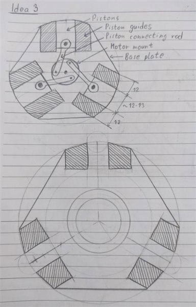
Above is a sketch of the mechanism I designed for this project, I will use the sketch just to explain the concept. The idea is to have a center rotating crank with 3 pistons rods attached to 3 pistons which are essentially in 3 small cylinders. By rotating the crank in the center with a servo, we can extended the pistons out of the body of the mechanism, or we can pull them back in. Design wise, there is just a couple things to be vary of, the angles at which the piston rod will attack the piston and leaving enough tolerances. This of course the mechanism found in almost all car internal combustion engines (let's not forget the Wankel engine!) and the tolerances there need to be fine because of the incredibly high pressures, while for this, we just need the piston to go in and out. Give it a bit of slop and doing the angles so the piston rods push more into the piston rather than the piston walls, ensures we have a mechanism that will work pretty good. Here is a video of the old mechanism working, turned by hand.
The next step for that project was of course adding a servo motor to the whole thing and here is how it worked with that. The mechanism worked without any issues what so ever, it just need a bit of guess work at what angles the servo needs to go to get the full range without overextending and pushing the pistons out of the cylinders.
So that's where the idea for this mechanism came from, but there is one pretty big problem in this design, and that is, it's too big. While I could technically mount this to the end of my robot, you can see how bulky the whole mechanism is, and it was pretty heavy considering it was using a standard sizes servo. One thing to note about that mechanism is that I made it by hand from scratch using wood and metal pieces I had laying around, this time I can use 3D printing to get a really compact design.
3. Plan
Inspired by the design I've shown the plan for this mechanism is to design it in Fusion360 and make it as small possible, because the less mass we have on the top of the robot the better, and everything else will be much smaller as well. Let's begin with some sketches.
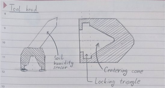
This sketch shows my general plan for this, which went to the final version. There is a centering cone and a locking triangle. The centering cones purpose is, well, as the name suggest, to center the robot to the tool. Because the robot isn't that accurate to make sure it engages with the tool head every time, this cone will make sure even if there's a bit of play in the mechanism, it will still work. The locking triangle will be used to capture the pistons from the central mechanism to lock the tool in place. On the left you can see how I plan on mounting the soil humidity sensor.
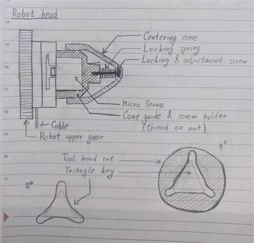
This is a sketch that covers more of the mechanism itself. You can see the robot gear on the top picture to which I need to mount everything, There are 8 holes on that gear that allow me to mount anything using M4 screws. Above that is the small servo which will turn the crank and push the pistons out, and on top of that is a spring loaded cap. Now let's get into why I have a spring loaded cap on top. If I did the mechanism without the spring cap what would happen? The mechanism would go into the tool, extend the pistons and lock in place. If the dimensions are not completely perfect, either the pistons won't engage properly, or there will be a small gap between the top of the cap and the mechanism, giving us some slop in the mechanism. By adding a spring loaded cap, we ensure, that even if we have some dimensional errors, everything will fit properly, and furthermore, when the pistons are in their holes the springs will cause tensions in the mechanism making it more robust. The only thing to watch out for here is that the robot needs to compress the springs when engaging with the tool head, which isn't hard to accomplish. On the bottom of the page you can see the drawings for how the keying mechanism should look like. The holes for the pistons need to have a bit of a fillet on the edges to guide the piston into the hole, since there is a change it will be off by a couple of millimeters. These sketches are of course just the concept idea, let's see how this will go when we start designing it in 3D part by part.
4. Design
As I've already mentioned, for the 3D design I will be using Fusion360. I've uploaded all of the models on GitHub, which you can find here. The link for the whole project on GitHub can be also found on the bottom of every blog, and I'll have the link for the folder for this models again, at the end of this section. Let's now go into designing our model, first off, there are some stuff that are off the shelf, that we need to incorporate into the design, so let's firstly model them up and go with the design from there.
Off the shelf components
There are 4 different off the shelf components as part of this mechanism, a Micro SG90 servo motor, 2 types of screws and small springs. I didn't really need to make all of them in 3D, but it just made it easier to have a whole assembly in the end, to see if everything fits together as it should. Here are those models and their specification.
| {tabbedtable} Tab Label | Tab Content |
|---|---|
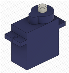
SG90 Servo | This is the servo that anyone that has an Arduino has probably had at one point or another. It's really easily accessible and it isn't expensive at all. This 3D model isn't too accurate like some that can be found online, but all I needed was a model to know what kind of gaps I need to leave in the model for everything to work.
|
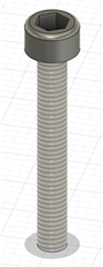
Screw 1 | These are the screws used to attach the motor mount to the base of this mechanism. It's an M3 screw with a hex head, it's thread is long 22m with the whole screw long 25mm. I'm using 3 of these to attach the parts together.
|
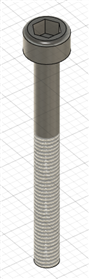
Screw 2 | These are the screws used as guides for the spring loaded cap. There are 4 of them in total, they are also M3 and are longer, but they have a smooth part near the head of the screws, so they can glide down and down the plastic without the threads catching.
|
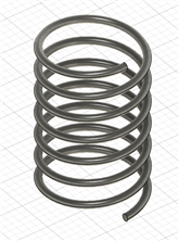
Spring | The last off the shelf part are the small springs used to push the cap. They are 7mm in diameter with 12mm in length, and the diameter of the wire used is 0.5mm. All of these models can be found on my GitHub link.
|
With that out of the way, we can focus on the hard part of this build, designing the custom 3D models,
Custom made parts
Now we come to the fun part, there will be 6 different parts here that will make our assembly. We will have the base and motor mount, which will make the body of our mechanism, we will have the barrel, which will be the center spinning crank, the pistons, the top cap and the sleeve template. I'll show you the designs now in order that I designed them in. The first model was the SG90 servo and I went from there.
| {tabbedtable} Tab Label | Tab Content |
|---|---|
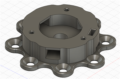
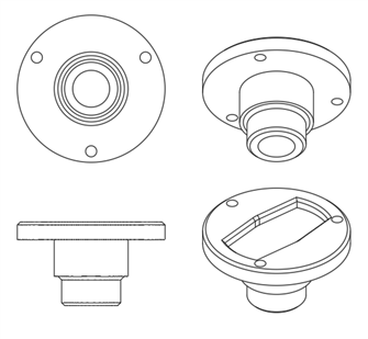
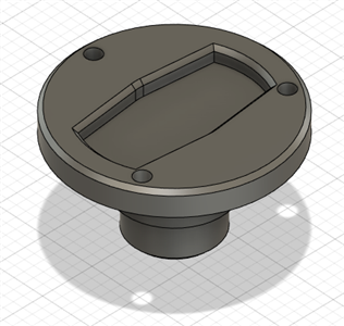
Base | We will begin with the base of this mechanism, let's define what the base needs to do first. The base needs to have the holes for attaching the whole mechanism to the robot, part of it will be the cylinders that will be used as guides for the pistons, we need a hole for the cable routing and we need holes for attaching the motor mount to it.
It has a hole in the bottom in the center which is used as a brace for the barrel when turning as well as for tightening the screw that attaches the motor adapter to the servo motor.
|
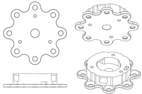
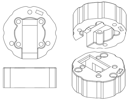
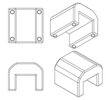
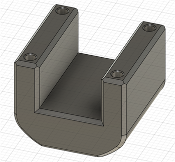
Motor Mount | This is the part that holds the motor with 2 small screws I found laying around (though some super glue will work fine too) and attaches on top of the base. It needs to have the cable routing hole in the same place as the base, 3 screw holes for attaching to the base, and 4 more holes for the screws which will go upside down and used for the cap. Here is the technical drawing for this part.
It's a pretty straight forwards part, it was modified along the way to fit everything and that's how I got it in the end.
|
Barrel | Barrel is the spinning crank in the middle which will attach to the pistons. To attach to the pistons I used some solid copper wire which I bent with pliers which I'll show in the end. The barrel has a hole in the top part to fit the motor adapter that comes with the motor, I just cut off the ends to make it a bit smaller.
|
Pistons | This was the simplest part to make by far, it's a small rectangular piston, I made the tolerances so it's about 0.2-0.3mm smaller than the cylinder hole on the base. At the back of the piston there is a small rod to which you attach the copper wire as a piston rod.
|
Cap | The cap is the part going above the servo which is spring loaded by the 4 small springs already mentioned. It has 4 2.4mm holes for the M3 screws. One thing I didn't point out for the base, is that the holes for the screws are also 2.4mm so I can easily cut the thread into it. This is something I started doing recently and found to be very easy to do, while working absolutely great for me.
|
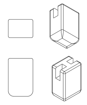
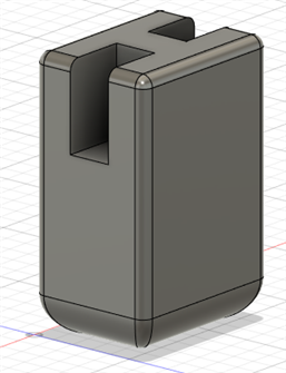
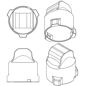
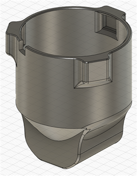
Sleeve Template | This part was the hardest to model and I didn't get it to work on the first try. This is the sleeve that goes over our mechanism that needs to push on the springs and align the holes with the small pistons. It looks like a weird cup currently, since it is only a test to see if the mechanism works. I will use this model later on to make special tool heads by adding features to it.
|
Finished Assembly
Those would be all of the parts needed for this assembly. Now, let's take a look at some sub assemblies and then at how the final assembly turned out. Another thing to point out is that I've designed all of the parts so they can be printed without any supports. I printed them on my Ender 3 Pro, using Creality White PLA, at 205C and 60C bed. The tolerances for the moving parts are 0.3-0.4mm, so most 3D printers will be able to handle that. I could have pushed for finer tolerances, but there really wasn't any need to. On this link, you can find STP files for all of the components if you wish to edit them in any way as well as STL files so you can slice them right away and print them. All of the filed are of course free to use, so you can do whatever you want with them!
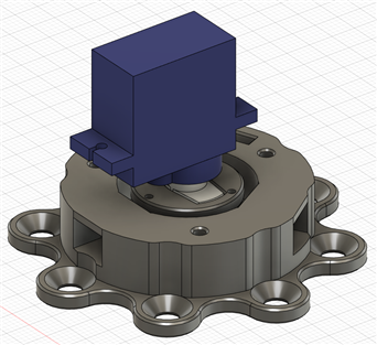
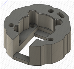
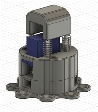
On this picture you can see how the base of the mechanism works with the barrel and the servo motor. There's a pretty big gap between the barrel and the base because I don't need them to be close and I've put chamfers on the bottom edges of all models to compensate a bit for the elephant foot while printing.
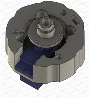
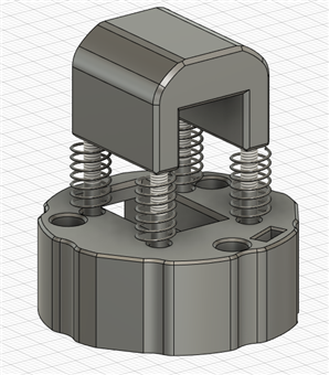
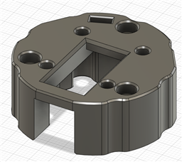
On these 2 pictures you can see the motor mount doing it's 2 jobs, holding the motor snuggly in place and on the second picture you can see how the top cap is mounted using the 4 screws and 4 springs. You can notice on the first picture that there are like channels around the motor, those are for the screw heads to go up and down when the cap is moving, and the square hole is for routing the flat 3 wire cable from the servo. Let's take a look at the full assembly now.
After a day of printing the parts one by one I had all of the parts complete. The only other thing that I needed was a bit of solid copper wire to make small connecting rods to connect everything together, which I'll show in the next section. This part required a bit of effort to make everything work, but it did in the end, in total, there were 114 different sketches for this design.
5. Finished mechanism
And finally, after all of that work, let's take a look at the finished parts. There aren't many pieces to the assembly and from the 3D models above, it's pretty straightforward with just a few screws. The only thing not covered above is the solid copper wire connecting rods. I had some 1.7mm thick copper wire (not sure what's the correct diameter, my calipers were showing 1.71-1.73mm). To get them to attach to both the pistons and the barrel it just needed a few twists, the wire in the end needs to look something like this:
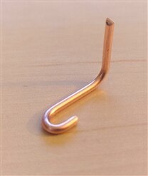
The hook that you can see at the bottom goes onto the center section that you can see on the model of the piston, while the vertical part goes into the barrel of the mechanism. To secure it in place, I just bent the wire at the end and cut off the excess after putting it through the barrel, here is how the finished result looks like.
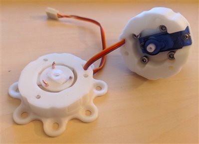
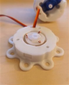
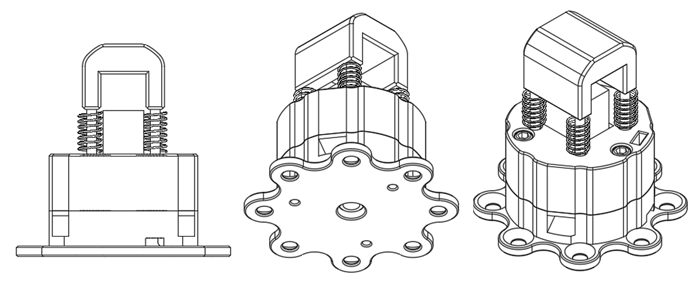
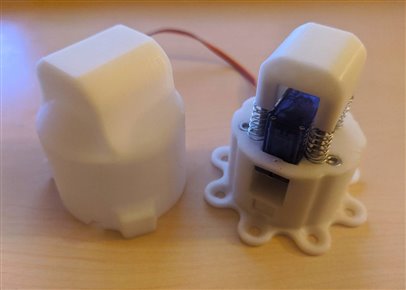
In both pictures, you can see the tips of the copper wire slightly bent so they can't come loose that easily from the barrel, looking at it now, I should have maybe bent and cut the wire first to the final shape before assembly, but since it's working great now, I really don't want to take it apart again. In the end, the whole mechanism with the template sleeve turned out like this.
All that's left to do now is to do some testing with this, to see how well it works. One thing I haven't mentioned is that I cut off the old connector, since of course, I couldn't get it through the routing for the cable part with it attached, but I crimped a new nylon connector on, to match the connectors that I'm using for the other servos on the robot. Before we get to testing, this is something I made in the meantime, since I'm working a lot with servos and needed an easy way to test them.
6. Servo Tester
While small, multi channel servo testers can be found easily for a really low price, I just wanted a small, simple and robust one that would allow me to test one servo. Another thing I wanted was to not have to go and look for any jumper wires to power the device on, but rather power it using a phone charger and a USB Micro port. So I decided to design a simple servo tester. I went with the easiest way of using an Arduino Nano, potentiometer, Micro USB port and a small 3 pin nylon connector. The potentiometer was connected to the analog pin and the power, while the servo was connected to the 5V and one of the PWM pins, then the reading on the input pin was mapped to an angle of 0 to 180 degrees which was used in the "servo.write(x)" command.
#include "Servo.h"
int angle, potentiometer;
Servo motor;
void setup() {
// put your setup code here, to run once:
motor.attach(3);
}
void loop() {
// put your main code here, to run repeatedly:
angle = map(analogRead(A0), 0, 1023, 0, 180);
motor.write(angle);
delay(50);
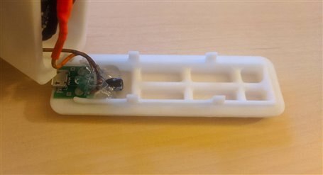
}The only thing needed for this project was an enclosure, so I designed one that snapped into place into a small box with openings for the USB port, the motor port and the potentiometer. Here are pictures of the 2 3D models of the enclosure for the servo tester.
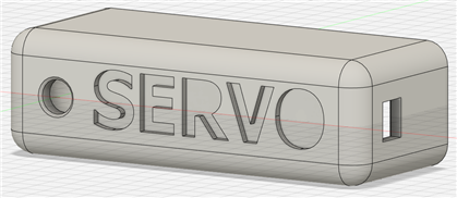
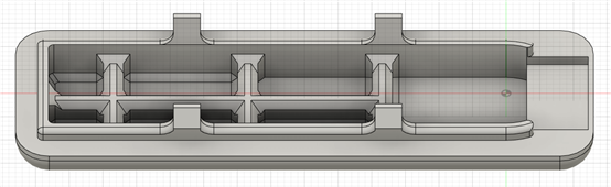
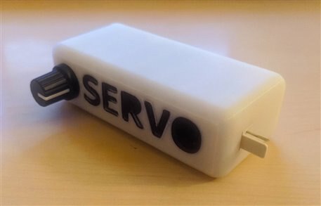
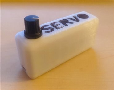
The first picture shows the enclosure of the servo tester, while the second picture shows the lid that goes on the bottom. The models are designed so they can be printed without any supports. To print them, I used, as I've already mentioned for the rest of the project. My Ender 3 Pro, with pretty standard settings, 205C and 60C for the bed, Creality White PLA (I found their PLA really does amazingly on my printer, it's the same filament that comes with the printer). As with all of the other models used in this project, you can find both the STP files as well as the STL files on this link: Servo Tester 3D models. You are free to do with the models whatever you want! Here is how the end product turned out like.
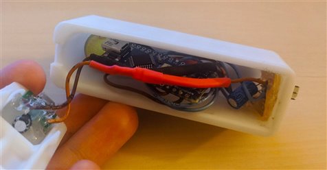
I just directly soldered the wires on the inside as there really weren't too many of them. Another that I added which you can see in both pictures are capacitors, both at the USB port and at the nylon motor connector. In my experience, servos love to draw a few spikes from time to time, so this is just a way to make sure everything runs smoothly, though, since I'll be using this only on small servos, I could have probably done everything without using any capacitors at all.
With the servo tester complete, we can finally see a few test videos for the quick tool change mechanism!
7. Testing
Time for the fun part! Testing the thing we were designing and making. It's such an incredible experience seeing something work as it should after putting in the time to get something from an idea to a physical thing. To start off the testing, let's take a look at the mechanism extending the pistons and retracting them without doing anything else, and then slowly go further.
That was the easy part, now let's see how it works with the sleeve template that I've printed out. Before getting to the video, just a quick reminder, to engage the mechanism with the sleeve template, the sleeve template needs to compress the springs a bit, as much as it can which isn't a lot, so the pistons can line up approximately with the holes on the sleeve. And then, when we extend the pistons, there should be a strong mechanical linkage.
It works! Honestly, I'm thrilled with how good it's working. I knew it was going to lock in place but I didn't how much slop it would have since the springs aren't that strong, but I'm happy to say it's holding on really really good. This far exceeds my expectations that I had for it. The only thing left now is to mount it to the robot and see how strong the mechanical link is.
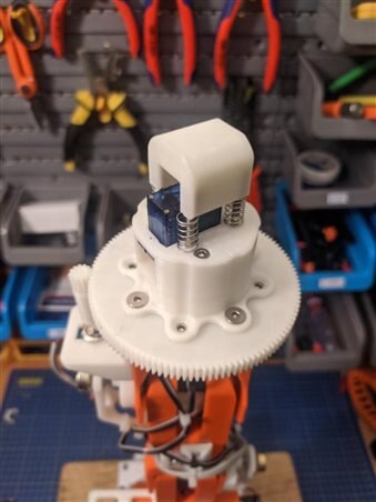
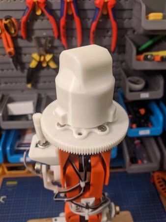
I love how it looks on the top of the robot! The size of the whole contraption isn't too big at all, specially if I'm start with the tool designs later on, this will work without any problems whatsoever. To test the strength of the mechanical bond, let's see if it's strong enough to withstand the mass of the whole robot and the giant wooden block that the robot is mounted too.
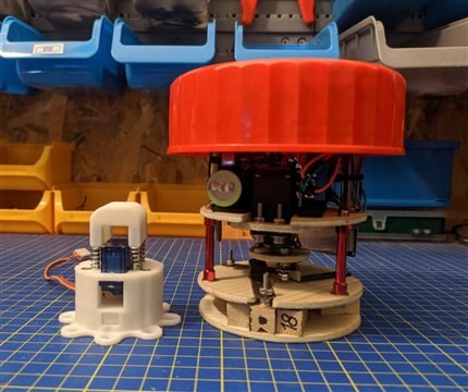
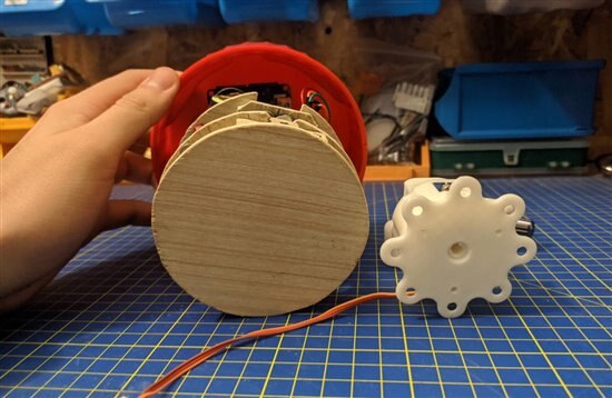
Didn't even break a sweat, and this block of wood is pretty heavy. The sleeve has minimal movement on the mechanism when it's engaged, it can rotate around it's axis by a fraction of a degree, but that's all, it will do the job really good for sure, I can't wait to put actual tools on the top. In the end as a cool bonus, I still have the jar mechanism I made last year, here is how they compare in size to another, I was able to get this one much more compact than the last year version, though, of course, with a much different set of tools and materials compared to the last time.
8. Further development
With this, I have the base unit for the quick tool change mechanism complete. I won't be changing anything on the mechanism later on, one thing I might to, is give a slight cone shape to the motor mount to take off excess material and help it align easier with sleeve template. One thing that will be changing of course, is the sleeve template. While it's working great like it is now, as you can see from the videos, it doesn't have one thing taken into account and that's tool storage. I'll need to make a bay that will hold all of the tools for the robot and the sleeve will need to have some kind of a feature on it, that will always hold in place in that part in the same way, that can be as simple as a small ring indentation in the sleeve template, but I'll look into that when I get to it. And of course, the sleeve will be modified according to the tool that will be used at the top. Once I figure out the tool holder, another thing that will be added will be one part of the magnetic connector which I covered 2 blogs ago. But the main and hardest part for this part of the build is complete!
9. Fun news from the ISS
While this won't news that are actually happening on the ISS, it's an experiment carried out by space agencies. The project is called EDEN ISS. They placed small laboratories/growing stations on Antarctica where they are successfully growing vegetables at you can imagine what conditions. They are using a closed loop system, and their research can help indoor farming as well as farming in space. Here is a short video about this project, looks amazing!
10. What's next?
Next on the line will be the Sensor & Light module and playing around with communication between Raspberry and Arduino. The module is close to being finished with just a bit of soldering left and coding left, while for the communications part I want to play around a bit with the Raspberry and Arduino. I want to try out I2C between them a bit as well as test out controlling our astronaut sending out commands using the Raspberry. Besides that, I'm working on the 12V power supply which will be similar to the 5V one I made already and on the main construction of this project. That will take me about a day to make everything out of wood, with a few more hours for mounting the rails and trying out to see how the robot moves up and down the rails! The next blog will be linked at the end of this blog once it is published!
11. Summary
This was a build I was scratching my head about for quite some time now, because I wanted to make it simple yet capable for what I need it. I'm really pleased with the result in the end and can't wait to have the magnetic connector attached as well to test it out properly. I'm also really pleased to say that there weren't any major hick ups with this build, the only thing I had to redesign were the pistons, since the first version didn't fit, the tolerances were bad and the sleeve template, because of a small mistake I overlooked which cause the template unable to go over the mechanism completely. All of the relevant links for this competition, link to the next and previous blog as well as my GitHub where I'm uploading all of the models can be found underneath. Thanks for reading the blog, hope you liked it and found it interesting!
Milos
Relevant links for the competition:
Link to my GitHub where you can find all of the files used for this project (code, 3D models,...):
Link to my Project Collection:
| Previous Blog | Next Blog |
|---|---|
| Project R.A.G. - Blog #3 - Lift Off | Project R.A.G. - Blog #5 - Sensor & Light Module |
Top Comments
-

phoenixcomm
-
Cancel
-
Vote Up
+1
Vote Down
-
-
Sign in to reply
-
More
-
Cancel
-

milosrasic98
in reply to phoenixcomm
-
Cancel
-
Vote Up
+1
Vote Down
-
-
Sign in to reply
-
More
-
Cancel
-

phoenixcomm
in reply to milosrasic98
-
Cancel
-
Vote Up
+1
Vote Down
-
-
Sign in to reply
-
More
-
Cancel
Comment-

phoenixcomm
in reply to milosrasic98
-
Cancel
-
Vote Up
+1
Vote Down
-
-
Sign in to reply
-
More
-
Cancel
Children