


Table of Contents
Introduction
This blog is about interfacing the LED bar with the PSoC CY8CKIT-062S4 board through its vast number of IOs provided in the Arduino shields. It is one of the secondary modules in this project. Overall this involves writing up the logic to control 10 LEDs which will light up according to the Ambient Light Sensor(ALS) value reported by the onboard sensor. The process of obtaining these ALS and Temperature values is discussed in the previous blog and extending that, we'll now see about displaying it to the user.
Running on Cortex M4 Core
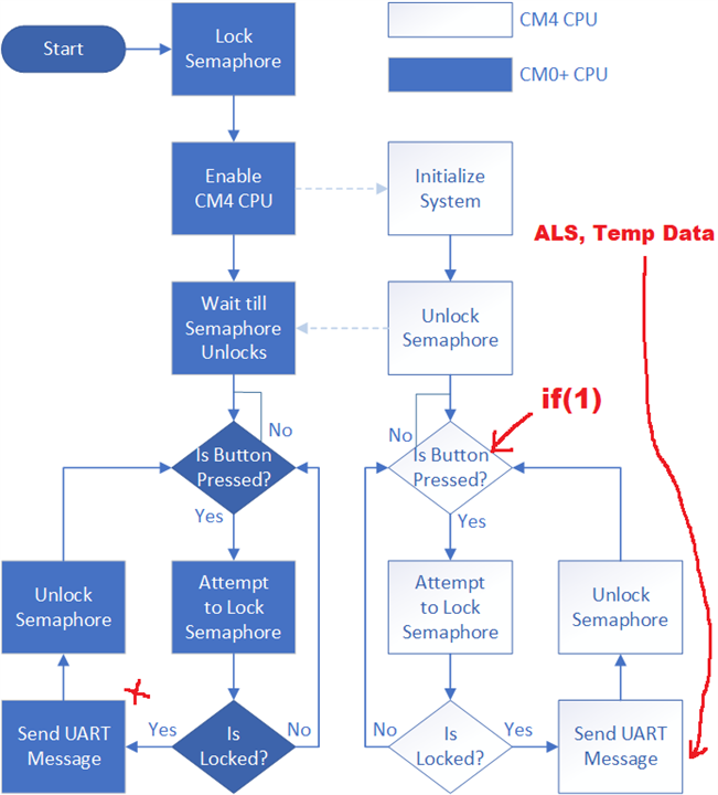
This implementation built on top of the code from the previous blog. In this dual-core application, the flow starts from Cortex M0+ (CM0+), enabling the larger Cortex M4 (CM4) core that initializes the IOs and subsystems within the application. We have seen how this whole flow works with both the cores sending UART messages and controlling the LED. Now with this LED bar interfacing, for real-time updates of the bar graph, the program flow is made to follow the loop in CM4 as highlighted. I suppose this can also be done probably in a more efficient way by activating an interrupt in a frequency when new data appears on ALS. Or even doing the process of query every 500ms or so and running through the loop on each core.
Code
Contains:
1. 2D array implementation for LED bar indication
2. ALS brightness threshold level definitions
3. Logic to pick the LED series from the matrix based on ALS levels
4. Print the ALS and temperature sensor values over UART
| {tabbedtable}Files | Code |
|---|---|
| ledbar.h | /*
* ledbar.h
*
* Created on: 16-Apr-2023
* Author: Navadeep
*/
#ifndef LEDBAR_H_
#define LEDBAR_H_
#define ALS_THRESH_LEVEL1 10
#define ALS_THRESH_LEVEL2 20
#define ALS_THRESH_LEVEL3 30
#define ALS_THRESH_LEVEL4 40
#define ALS_THRESH_LEVEL5 50
#define ALS_THRESH_LEVEL6 60
#define ALS_THRESH_LEVEL7 70
#define ALS_THRESH_LEVEL8 80
#define ALS_THRESH_LEVEL9 90
#define ALS_THRESH_LEVEL10 100
typedef enum
{
eALSLevel1 = 0,
eALSLevel2,
eALSLevel3,
eALSLevel4,
eALSLevel5,
eALSLevel6,
eALSLevel7,
eALSLevel8,
eALSLevel9,
eALSLevel10,
eALSLevelMax
}TeALSIndicateLevels;
typedef enum
{
eLed1 = 0,
eLed2,
eLed3,
eLed4,
eLed5,
eLed6,
eLed7,
eLed8,
eLed9,
eLed10,
eLedCountMax
}TeALSLed_t;
typedef enum
{
eLedStateOff = 0,
eLedStateStatic,
eLedMaxStates
}TeLedState_t;
#endif /* LEDBAR_H_ */ |
| main.c (CM4) | static int ALSLevel = 0;
/*ALS LED states matrix array*/
static const uint8_t LedState[eALSLevelMax][eLedCountMax] = {
{eLedStateStatic, eLedStateOff, eLedStateOff, eLedStateOff, eLedStateOff, eLedStateOff, eLedStateOff, eLedStateOff, eLedStateOff, eLedStateOff},
{eLedStateStatic, eLedStateStatic, eLedStateOff, eLedStateOff, eLedStateOff, eLedStateOff, eLedStateOff, eLedStateOff, eLedStateOff, eLedStateOff},
{eLedStateStatic, eLedStateStatic, eLedStateStatic, eLedStateOff, eLedStateOff, eLedStateOff, eLedStateOff, eLedStateOff, eLedStateOff, eLedStateOff},
{eLedStateStatic, eLedStateStatic, eLedStateStatic, eLedStateStatic, eLedStateOff, eLedStateOff, eLedStateOff, eLedStateOff, eLedStateOff, eLedStateOff},
{eLedStateStatic, eLedStateStatic, eLedStateStatic, eLedStateStatic, eLedStateStatic, eLedStateOff, eLedStateOff, eLedStateOff, eLedStateOff, eLedStateOff},
{eLedStateStatic, eLedStateStatic, eLedStateStatic, eLedStateStatic, eLedStateStatic, eLedStateStatic, eLedStateOff, eLedStateOff, eLedStateOff, eLedStateOff},
{eLedStateStatic, eLedStateStatic, eLedStateStatic, eLedStateStatic, eLedStateStatic, eLedStateStatic, eLedStateStatic, eLedStateOff, eLedStateOff, eLedStateOff},
{eLedStateStatic, eLedStateStatic, eLedStateStatic, eLedStateStatic, eLedStateStatic, eLedStateStatic, eLedStateStatic, eLedStateStatic, eLedStateOff, eLedStateOff},
{eLedStateStatic, eLedStateStatic, eLedStateStatic, eLedStateStatic, eLedStateStatic, eLedStateStatic, eLedStateStatic, eLedStateStatic, eLedStateStatic, eLedStateOff},
{eLedStateStatic, eLedStateStatic, eLedStateStatic, eLedStateStatic, eLedStateStatic, eLedStateStatic, eLedStateStatic, eLedStateStatic, eLedStateStatic, eLedStateStatic}};
/*core for loop program*/
for (;;)
{
if (1); //or if(cyhal_gpio_read(CYBSP_USER_BTN) == CYBSP_BTN_PRESSED));
{
#if ENABLE_SEMA
/* Attempt to lock the semaphore */
if (Cy_IPC_Sema_Set(SEMA_NUM, false) == CY_IPC_SEMA_SUCCESS)
#endif
{
/* Print a message to the console and turn Orange LED ON*/
cyhal_gpio_write(CYBSP_USER_LED2, CYBSP_LED_STATE_ON);
printf("Message sent from CM4\r\n"); /*UART transmit message*/
/*Also send sensor data*/
/* Wait till printf completes the UART transfer */
while(cyhal_uart_is_tx_active(&cy_retarget_io_uart_obj) == true);
/*Bar LED display logic*/
if(light_intensity < ALS_THRESH_LEVEL1)
{
ALSLevel = eALSLevel1;
}
else if(light_intensity < ALS_THRESH_LEVEL2)
{
ALSLevel = eALSLevel2;
}
else if(light_intensity < ALS_THRESH_LEVEL3)
{
ALSLevel = eALSLevel3;
}
else if(light_intensity < ALS_THRESH_LEVEL4)
{
ALSLevel = eALSLevel4;
}
else if(light_intensity < ALS_THRESH_LEVEL5)
{
ALSLevel = eALSLevel5;
}
else if(light_intensity < ALS_THRESH_LEVEL6)
{
ALSLevel = eALSLevel6;
}
else if(light_intensity < ALS_THRESH_LEVEL7)
{
ALSLevel = eALSLevel7;
}
else if(light_intensity < ALS_THRESH_LEVEL8)
{
ALSLevel = eALSLevel8;
}
else if(light_intensity < ALS_THRESH_LEVEL9)
{
ALSLevel = eALSLevel9;
}
else if(light_intensity == ALS_THRESH_LEVEL10)
{
ALSLevel = eALSLevel10;
}
/*Update LED status*/
cyhal_gpio_write(CYBSP_D0 ,LedState[ALSLevel][eLed1]);
cyhal_gpio_write(CYBSP_D1 ,LedState[ALSLevel][eLed2]);
cyhal_gpio_write(CYBSP_D2 ,LedState[ALSLevel][eLed3]);
cyhal_gpio_write(CYBSP_D13 ,LedState[ALSLevel][eLed4]);
cyhal_gpio_write(CYBSP_D4 ,LedState[ALSLevel][eLed5]);
cyhal_gpio_write(CYBSP_D5 ,LedState[ALSLevel][eLed6]);
cyhal_gpio_write(CYBSP_D6 ,LedState[ALSLevel][eLed7]);
cyhal_gpio_write(CYBSP_D7 ,LedState[ALSLevel][eLed8]);
cyhal_gpio_write(CYBSP_D8 ,LedState[ALSLevel][eLed9]);
cyhal_gpio_write(CYBSP_D10 ,LedState[ALSLevel][eLed10]);
/* Print the temperature and the ambient light value*/
printf("Temperature: %2.1lfC Ambient Light: %d%%\r\n", temperature, light_intensity);
printf("\n");
cyhal_system_delay_ms(500);
cyhal_gpio_write(CYBSP_USER_LED2, CYBSP_LED_STATE_OFF);
#if ENABLE_SEMA
while (CY_IPC_SEMA_SUCCESS != Cy_IPC_Sema_Clear(SEMA_NUM, false));
#endif
}
}
} |
| main.c (CM0+) | for (;;)
{
/* Check if the button is pressed */
if (Cy_GPIO_Read(CYBSP_SW2_PORT, CYBSP_SW2_PIN) == 0)
{
#if ENABLE_SEMA
if (Cy_IPC_Sema_Set(SEMA_NUM, false) == CY_IPC_SEMA_SUCCESS)
#endif
{
/* Print a message to the console and turn Red LED ON */
cyhal_gpio_write(CYBSP_USER_LED, CYBSP_LED_STATE_ON);
Cy_SCB_UART_PutString(CYBSP_UART_HW, "Message sent from CM0+\r\n"); /*UART transmit message*/
cyhal_system_delay_ms(500);
cyhal_gpio_write(CYBSP_USER_LED, CYBSP_LED_STATE_OFF);
#if ENABLE_SEMA
while (CY_IPC_SEMA_SUCCESS != Cy_IPC_Sema_Clear(SEMA_NUM, false));
#endif
}
}
} |
Activating IOs using Device Configurator
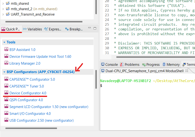
Device configurator is one of the interesting, handy and intuitive tools available in ModusToolbox which certainly makes the boring task of initializing peripherals, setting properties and doing that repeatedly for n number of IOs and peripherals we initialize. It is available in the Quick Panel window and will be specific for each project dynamically changing on the chosen project in the Projects Explorer window. The quick panel seems very useful giving options to build, debug and run with the project name shown there itself and it makes you aware what project you're deploying which would be rather confusing to do from the top panel while having multiple projects. I've specifically faced this issue of other/previous projects being taken from build and debug while on a different one operating from the top ribbon panel.
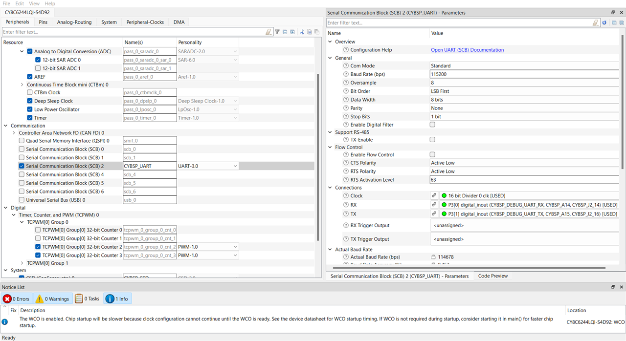
This has most of the configurations handy and I set the peripherals to be initialized and their specifications from the first panel and then going to the Pins tab to select GPIO pins and their functionality feature. For this project, UART to do the sensor data transmission serially and multiple GPIOs for driving the LED bar are needed to be initialized(extras exist to be ignored as I am extending the project from there)
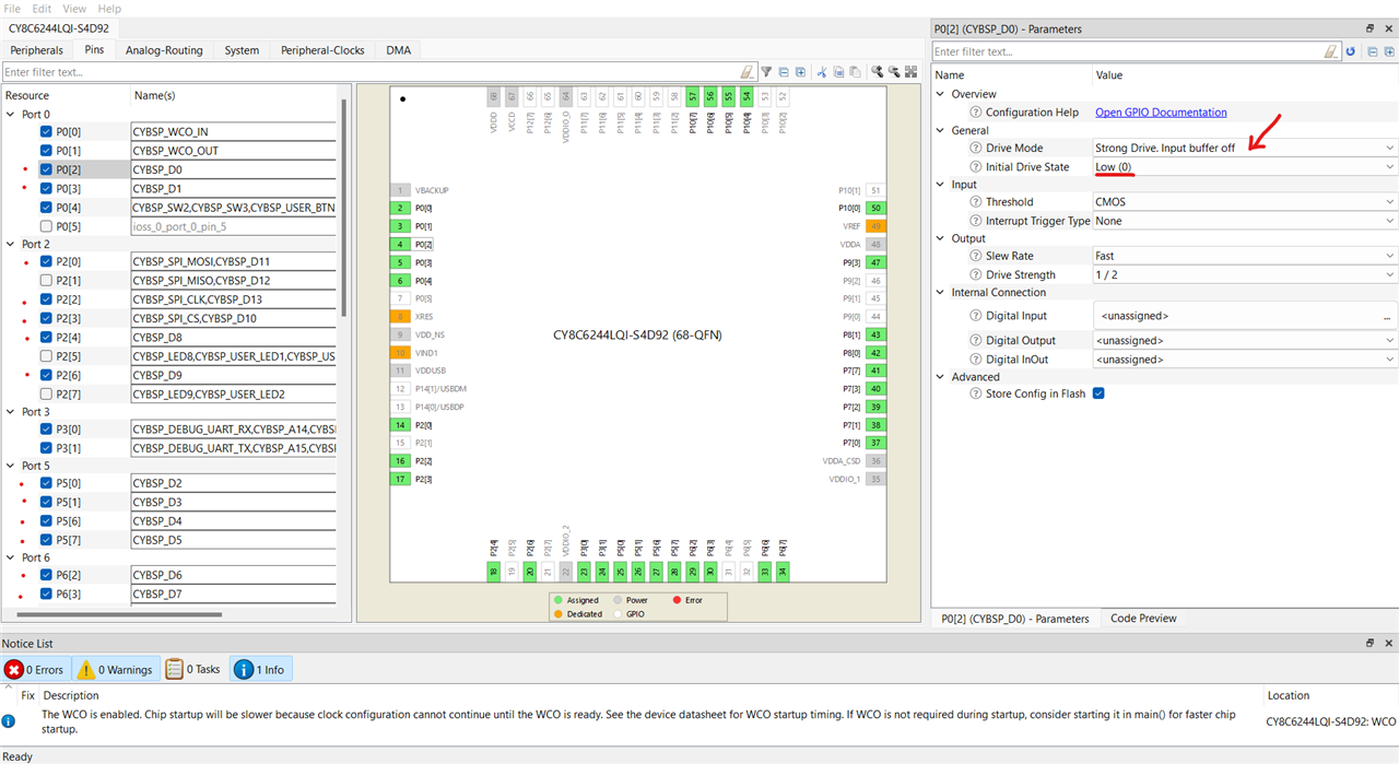
10 IOs are initialized with Strong Drive, default 0 state from D0 to D13 pins(arduino header) as some of them were preoccupied with other functions.
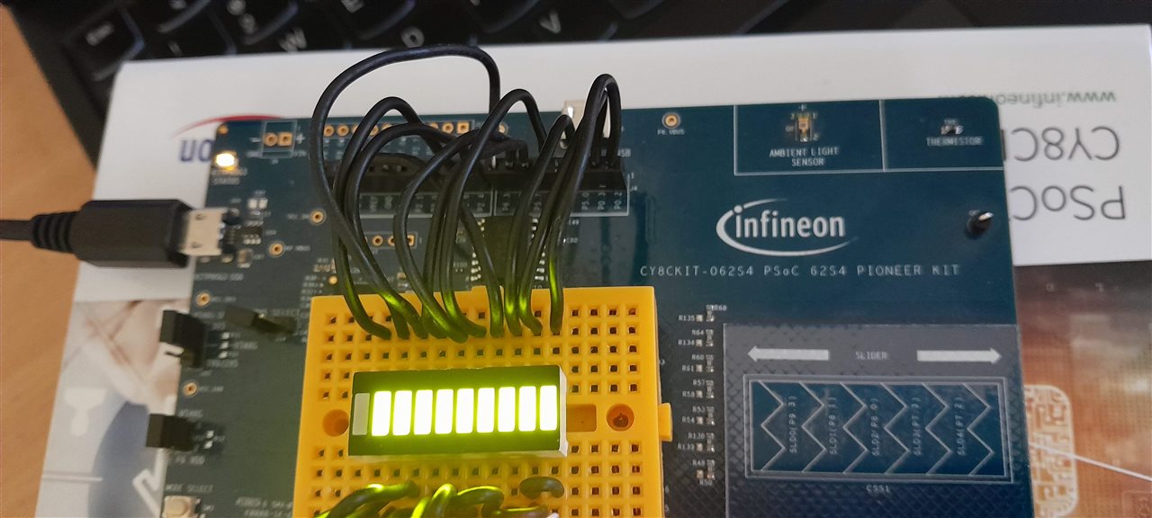
All the configurations here got updated immediately and reflected in the project as soon as it is saved with ctrl+S. We now are all set to go ahead with hefty wiring for the 10-segment LED bar and test out the code.
Interfacing LED Bar and Testing
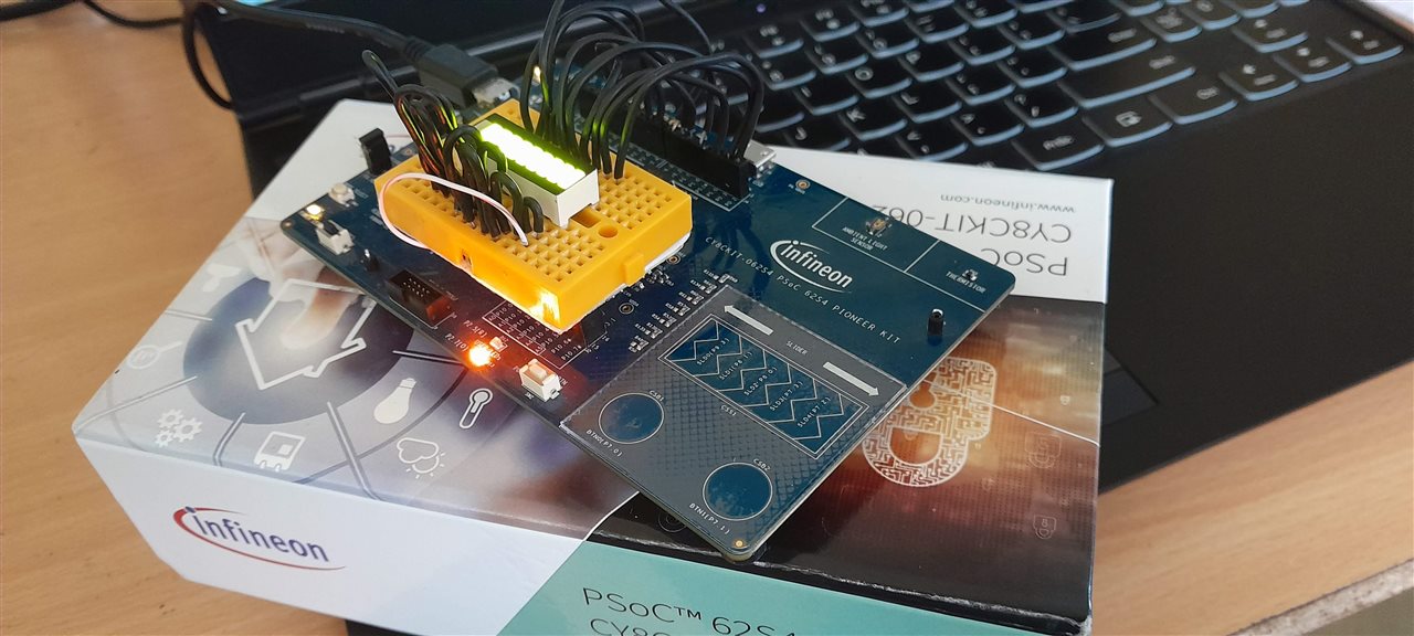
Videos
This being one of the modules running on CM4 with sensor data acquisition, LED interface and display happening from here in CM4, the other CM0+ core involves Capsense buttons and a slider for controlling a 2-channel PWM generated for motor control which we'll discuss in the next blog. Thanks for reading through and would love to know your thoughts. Thank you :)
Also Read:

