


| Previous posts | Description |
|---|---|
| BIBoP 1 - Introduction, game plan and rationale | Introduction to the project and overview, creators bios |
| BIBoP 2 - Writing Arduino code with C++ and C (Makefiles) | Using a custom Makefile for development of Arduino code, flashing and debugging code |
| BIBoP 3 - Blood Pressure Inference - Machine Learning | The process of creating a Machine Learning model for Blood Pressure estimation, data cleaning and training the model |
| BIBoP 4 - AWS Lambda deployment and MQTT communication | Deploying the trained model on the AWS Lambda and sending secure requests from the Arduino |
| Next posts | Description |
|---|---|
| Assembly and debugging | Assembly, 3D designing and debugging of the project |
| Galvanometer creation | Process of creating my own galvanometer |
| Final product and testing | Presentation of finished product and some results |

Introduction
Hello! In case this is your first time with BIBoP it is a smart armband designed for remote patient monitoring and overall health assessment. It is based on Arduino Nano 33 IoT and some external sensors (PPG, Galvanometer and IMU).
Be sure to regularly check the official repository of this project!
In this blog post we will go through the power management of our device, different states, generating and handling interrupts on register level and discuss some issues we had along the way. Let's get started!
Why use less power?
Since we want our device to run on battery and want this battery to last longer than an hour, we need to make the power consumption lower than usual. amgalbu in his blog post measured the current consumption of the Arduino under different circumstances, which helped us assess how much power reduction we require in order to have at least 2-3 days on a single charge and we can have even more assuming we use the device less extensively. It all boils down to tradeoffs we are willing to pay and to the voltage and current of our device  . It is no wonder why the medical-grade embedded devices or smartwatches run on microAmp current with voltages as low as under 1V.
Basing on Ambrogio's measurements and adding our own, we came up with following estimates for battery expectancy on a single charge:
| State | Current consumed | Time (minutes in hour) |
|---|---|---|
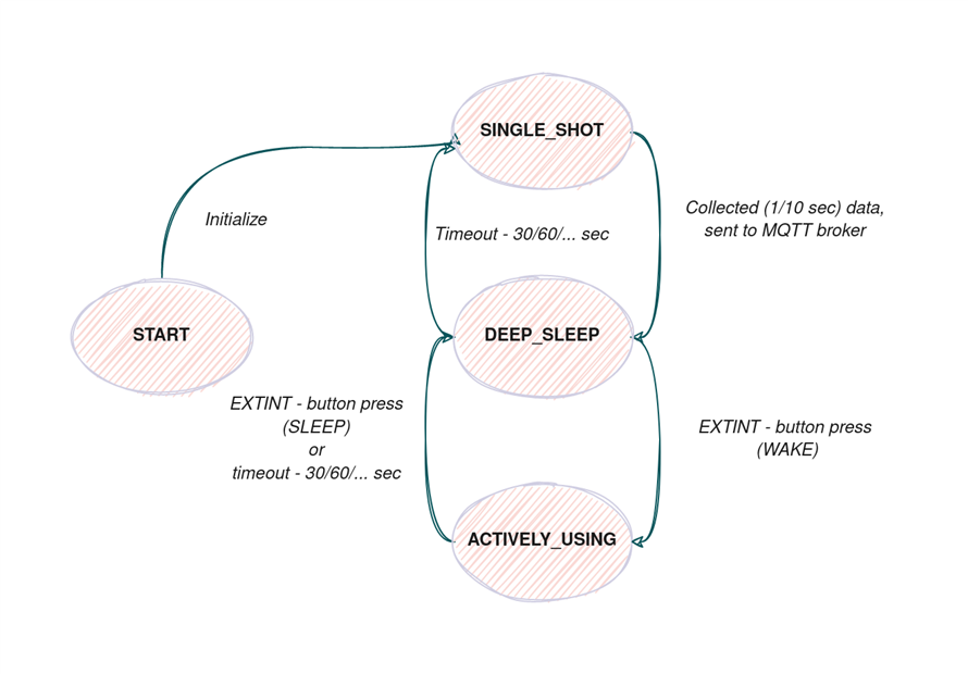
| SINGLE_SHOT | 50 | 5 min (5s every 60 seconds) |
| DEEP_SLEEP | 5 | 52 min |
| ACTIVELY_USING | 200 | 3 min |
NOTE: these are only estimates and the accurate measurements will follow once we finish assembling the device.
Hence, the estimate working time for 600mAh battery is around 32 hours, which is non-ideal but good enough for a prototype (we wouldn't be working in 3.3V but with much less ideally).
The power states of the system look as follows:
We can have the main loop running more or less frequent depending on the clients desire.
Battery and powering
For powering the system we are using raw Arduino pins (we could also use a limiting circuit so we don't accidentally fry our Arduino  - it is always good to have some kind of protection - boards are expensive, passive components not so much!
Initially we planned to use a Li-Po battery cell akin to those used in RC cars and drones, but it had too big voltages and we found out that there exists a type of battery providing us with the just right voltage most of the time - LiFePO4! It boasts recharge-ability and better efficiency than Li-ion ones. Also the voltage is mostly flat when the battery discharges, only decaying rapidly when the battery is almost empty which is desired for our application. The graph below shows exemplary battery charge curves over time:
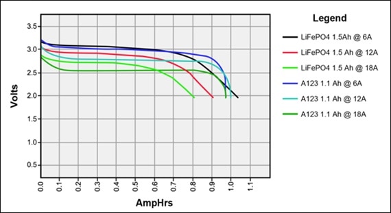
Credit: quora
As you can see, the graphs are very flat and this is what we need! Most of the devices onboard the Arduino need up to 3.6V and the LiPo battery would provide 3.7V when full. Maybe the only disadvantages are that charging these batteries is quite difficult and they have lower capacities (or I could not find bigger for less money).
I also found a simple DIY battery charger on hackaday.com which I will have to construct once the battery dies out!
The charger is making use of a popular element from TI - a programmable shunt regulator. The only problem with this charger is that you have to remember to switch it off to not overcharge the battery. It could be alleviated but as mentioned this is mostly a hack!
Using the RTC for sleeping
In his post amgalbu used the RTC onboard the SAMD21 for sleeping arbitrary time values in increments of 30.5 us (the tick value of the MCU). We tried the code and observed that somehow it sleeps 10 times less than asked for? So for now we are just inputting 10 times the value I need to sleep. In the blog post Ambrogio explains details behind the creation of the Generic Clock Generator (GCLK), however after spending considerable time reading the datasheet we think more explanation is needed!
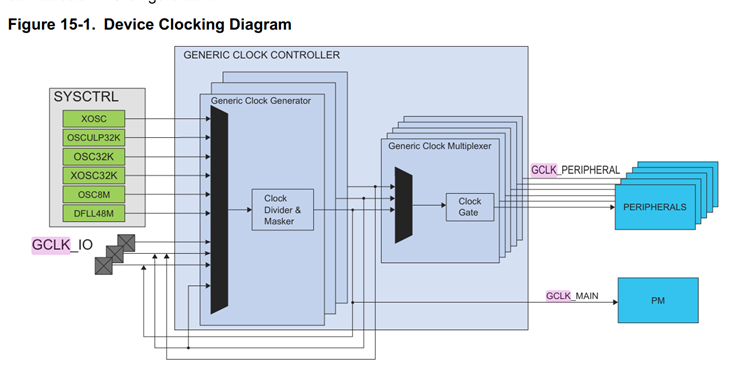
This research is motivated with a need for an external interrupt (button press) which will wake up the MCU even if it is in the DEEPSLEEP mode and the CPU is not running. In order to do so we need to dig deeper into several components of the system (GCLK, EXTINT) which are visible below:
First we need to create the GCLK and connect it to the External Interrupt Controller (EIC).
Onboard our MCU we have 9 GCLKs we can enable and then connect to peripherals. The code below creates one of them and connects it to the EIC:
    // create a generic clock generator for the EXTINT peripheral system
    GCLK->GENDIV.reg = GCLK_GENDIV_ID(3) |
                       GCLK_GENDIV_DIV(0);
    while (GCLK->STATUS.bit.SYNCBUSY);

    GCLK->GENCTRL.reg = GCLK_GENCTRL_ID(2) |
                        GCLK_GENCTRL_GENEN |
                        GCLK_GENCTRL_SRC_OSCULP32K;
    while (GCLK->STATUS.bit.SYNCBUSY);

    GCLK->CLKCTRL.reg = (uint32_t) (GCLK_CLKCTRL_CLKEN |
                        GCLK_CLKCTRL_GEN_GCLK3 |
                        (EIC_GCLK_ID << GCLK_CLKCTRL_ID_Pos));
    while (GCLK->STATUS.bit.SYNCBUSY);
As you can see there are three registers we need to configure: GENCTRL, GENDIV and CLKCTRL.
GENCTRL - Controls the generator and clock source
GENDIV - Controls the prescaler of the clock
CLKCTRL - Controls the Generic Clock Multiplexer
If you seek even more information about GCLK, be sure to check out this blog post and the official datasheet!
This is exactly how Arduino implements the interrupts and in the end I decided to use their wrapper functions. Nevertheless research I made is useful if you want to do all of this in a bare-metal environment (without Arduino libraries).
Knowing your MCU is useful if you want to assume control over it Oh and you don't have to go through the datasheet to figure everything by yourself!
Do interrupt me!
So now we know what the GCLK is and how to create them and register them for different peripherals in the MCU. Next we can use this knowledge to our benefit and enable the External Interrupt peripheral, which allows for setting IO pins to serve as interrupt lines. It even allows for supplying the NMI (non-maskable interrupt) to the MCU which is a big advantage - this interrupt cannot be masked (ignored by the MCU). We will not need it in this case, but it is good to have various options.
Basing on the graph above, we can start activating and configuring the necessary peripherals basing on EXTINT's requirements:
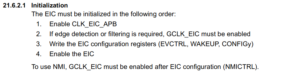
The first precondition is by default satisified, the second one we just configured, so now we will focus on the third one!
We are using a GPIO as an external interrupt so we have to configure it beforehand (This was probably the most difficult thing to set up for me!)
We are using pin Digital 9 - which corresponds to the PA20 in the GPIO peripheral.
    PORT->Group[PORTA].DIRCLR.reg |= PORT_PA20; // input
    PORT->Group[PORTA].OUTSET.reg |= PORT_PA20;
    PORT->Group[PORTA].PINCFG[20].reg = PORT_PINCFG_INEN | // enable input
                                       PORT_PINCFG_PMUXEN | // enable port muxing
                                       PORT_PINCFG_PULLEN;
    PORT->Group[PORTA].PMUX[20 >> 1].reg |= PORT_PMUX_PMUXE_A;
We first have to declare our pin as input by clearing a flag - writing 1 to DIRCLR for PA20. Then we enable internal pull-up to prevent the pin from floating (alternating between 0 and 1) by writing to OUTSET.
We then set up the PINCFG which sets up the settings for a given PIN, enabling PIN muxing which is responsible for setting alternative functions for the PIN, such as external interrupt.
With this done, we can setup EIC!
    // set up EXTINT
    // Pin Digital 9 = PA20 - connected to EXTINT4
    EIC->INTENSET.reg |= EIC_INTENSET_EXTINT;

    EIC->CONFIG[0].reg |= //EIC_CONFIG_FILTEN0 |
                          EIC_CONFIG_SENSE2_FALL_Val;

    EIC->WAKEUP.reg |= EIC_WAKEUP_WAKEUPEN4;
We can check which functions our PIN has by examining the variant.cpp file which shows our configuration for Arduino Nano 33 IoT.
We enabled external interrupt 4 which is connected to PA20 and set up the FALL detection meaning it triggers upon driving the pin LOW. We also enable it as a WAKE UP PIN.
Nested Vectored Interrupt Controller
The last part we need to set up is NVIC which enables the interrupts to the CPU from other peripherals in our MCU. The EIC line is tied also as NMI but we won't be using this functionality and just enabling the IRQs from EIC.
// set up NVIC
    NVIC_DisableIRQ(EIC_IRQn);
    NVIC_ClearPendingIRQ(EIC_IRQn);

    NVIC_SetPriority(EIC_IRQn, 0);
    NVIC_EnableIRQ(EIC_IRQn);
We have nice functions which abstract details of setting it from us and we can happily call them!
We also have to declare a handler for this interrupt like this:
void EIC_Handler(void)
{
     // handle it!
}
NVIC abstracts all the details from us, but in short, when an interrupt line (hardware connection to a peripheral like EIC) is driven high, it calls a function it has registered in the appropriate slot in its interrupt vector.
More details about it can be found here - you are in for a ride about weak functions and startup of SAMD21
Debouncing hell
It is also a good place to talk about debouncing, as even though we have prevented floating we still get intermittent states of the pin. There are various techniques on how to do this, be it hardware or software, but since we don't really care about whether our interrupt is acknowledged exactly when it came we can use software for that:
void buttonIrq()
{
    wakeUpMillis = millis();

    // needs debouncing in the button case
    if (wakeUpMillis - debounceMillis > BUTTON_PRESS_DELAY)
    {
        pressAcknowledged = true; // needs handling for OLED display changes
    }
    debounceMillis = wakeUpMillis; //millis don't advance in IRQ
}
Nevertheless, it is worth looking at various techniques of doing it: Part 1, Part 2.
Troubles along the way!
With the theory away, we could try implementing the actual handling in our code! Interrupts worked just fine, interrupting the device whether it was in the DEEPSLEEP or powered on.
However, as it turned out we soon stumbled upon big problem: when communicating with the MQTT broker, we could not gather data from our sensor and communicate with the OLED on the I2C bus. After several hours of debugging, it turned out that the ECCX08 is hogging our I2C bus with the amount of traffic it creates.
Without the regular hardware I2C bus we had to find a way around this problem.
Enter SAMD21 capabilities: creating new busses!
Creating new I2C bus
In order to create a new bus in SAMD21, some research has to be done beforehand about the pins we want to utilize and their capabilities. The ultimate guide to Arduino Nano 33 IoT mentions creating a hardware serial and the Sparkfun article explains how to create any bus we want.
We used pins Digital 5 and 6 for that and all we had to do was create a new TwoWire object tied to a free SERCOM instance:
// add a new serial because original one (pins A4 and A5) is hogged by the ECC
// D5 - SCL - pad 1
// D6 - SDA - pad 0
TwoWire sensorI2c(&sercom0, 5, 6);
And setup the pins:
// setup the second I2C bus

sensorI2c.begin();

pinPeripheral(5, PIO_SERCOM_ALT);

pinPeripheral(6, PIO_SERCOM_ALT);
We also have to tie devices to this bus and surprisingly some drivers do not have such capabilities.
One tweak I had to do to external libraries is also worth mentioning:
ArduinoMqttLibrary has hardcoded message callback format and when the MqttClient object is encapsulated, it is very hard to create this callback. I had to modify the library as follows:
And then tweak my NetworkManager class to handle the callback accordingly (I had to make some dancing around to make the function call properly). C++ classes make callback game much more difficult, so instead of just passing the member function I had to create a static function which in turn calls the member function.
If you are curious about how to do it differently, have a look here.
Summary
In this post we went through the power management system and different power states in our device. We also described some issues we had along the way and necesary modifications to some external libraries. In the penultimate post (next one ) we will describe a small addition to the device (Galvanometer) which was soldered on a small experimental board by us. Ideally it would be an SMD component but we lack SMD design capabilities at the time of writing this post (hopefully soon we will learn these arcanas!) Also we will show how the casing of BIBoP was designed and assembled and show our testing results.
Case sneak-peek(s)
Below is a sneak-peek of the casing for BIBoP, designed in fusion 360 by us!
| {tabbedtable} Tab Label | Tab Content |
|---|---|
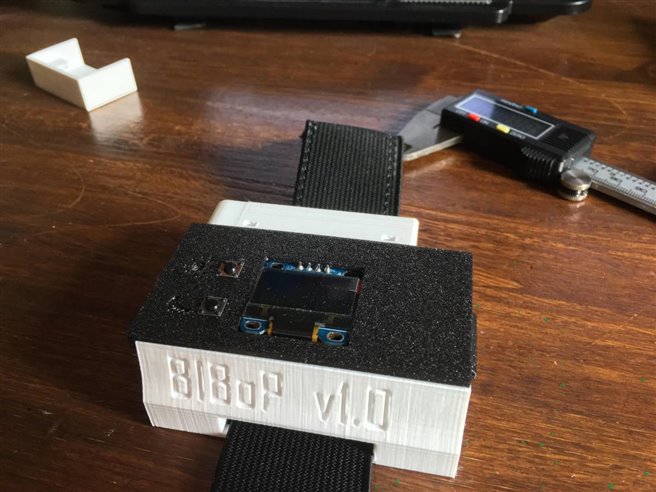
| Rendered 3D model | 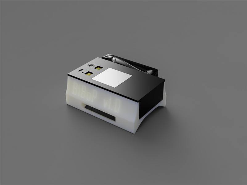 |
| assembled 3D print |
|
Jakub & Szymon & Michał
| Next post |
|---|
| Galvanometer creation |
Top Comments