element14 Community
element14 Community
    Register Log In
  • Site
  • Search
  • Log In Register
  • About Us
  • Community Hub
    Community Hub
    • What's New on element14
    • Feedback and Support
    • Benefits of Membership
    • Personal Blogs
    • Members Area
    • Achievement Levels
  • Learn
    Learn
    • Ask an Expert
    • eBooks
    • element14 presents
    • Learning Center
    • Tech Spotlight
    • STEM Academy
    • Webinars, Training and Events
    • Learning Groups
  • Technologies
    Technologies
    • 3D Printing
    • FPGA
    • Industrial Automation
    • Internet of Things
    • Power & Energy
    • Sensors
    • Technology Groups
  • Challenges & Projects
    Challenges & Projects
    • Design Challenges
    • element14 presents Projects
    • Project14
    • Arduino Projects
    • Raspberry Pi Projects
    • Project Groups
  • Products
    Products
    • Arduino
    • Avnet Boards Community
    • Dev Tools
    • Manufacturers
    • Multicomp Pro
    • Product Groups
    • Raspberry Pi
    • RoadTests & Reviews
  • Store
    Store
    • Visit Your Store
    • Choose another store...
      • Europe
      •  Austria (German)
      •  Belgium (Dutch, French)
      •  Bulgaria (Bulgarian)
      •  Czech Republic (Czech)
      •  Denmark (Danish)
      •  Estonia (Estonian)
      •  Finland (Finnish)
      •  France (French)
      •  Germany (German)
      •  Hungary (Hungarian)
      •  Ireland
      •  Israel
      •  Italy (Italian)
      •  Latvia (Latvian)
      •  
      •  Lithuania (Lithuanian)
      •  Netherlands (Dutch)
      •  Norway (Norwegian)
      •  Poland (Polish)
      •  Portugal (Portuguese)
      •  Romania (Romanian)
      •  Russia (Russian)
      •  Slovakia (Slovak)
      •  Slovenia (Slovenian)
      •  Spain (Spanish)
      •  Sweden (Swedish)
      •  Switzerland(German, French)
      •  Turkey (Turkish)
      •  United Kingdom
      • Asia Pacific
      •  Australia
      •  China
      •  Hong Kong
      •  India
      •  Korea (Korean)
      •  Malaysia
      •  New Zealand
      •  Philippines
      •  Singapore
      •  Taiwan
      •  Thailand (Thai)
      • Americas
      •  Brazil (Portuguese)
      •  Canada
      •  Mexico (Spanish)
      •  United States
      Can't find the country/region you're looking for? Visit our export site or find a local distributor.
  • Translate
  • Profile
  • Settings
Design For A Cause 2021
  • Challenges & Projects
  • Design Challenges
  • Design For A Cause 2021
  • More
  • Cancel
Design For A Cause 2021
Blog Smart Exhibit: Blog #4: Electronic schematic, system building and sanity checks
  • Blog
  • Forum
  • Documents
  • Polls
  • Files
  • Mentions
  • Sub-Groups
  • Tags
  • More
  • Cancel
  • New
  • Share
  • More
  • Cancel
Group Actions
  • Group RSS
  • More
  • Cancel
Engagement
  • Author Author: alexandru.cohal
  • Date Created: 9 Apr 2021 9:16 PM Date Created
  • Views 637 views
  • Likes 4 likes
  • Comments 4 comments
  • sanity check
  • smart exhibit
  • system building
  • schematic
  • design for a cause
Related
Recommended

Smart Exhibit: Blog #4: Electronic schematic, system building and sanity checks

alexandru.cohal
alexandru.cohal
9 Apr 2021

Hello!


As explained in my previous blog post ( Smart Exhibit: Blog #3: The hardware components ), I need some extra components (temperature, humidity, light, sound and motion sensors, speaker, push-button, battery and battery charger) for my project, Smart Exhibit. Last week I received these components together with the Arduino Nano 33 IoT board image So, I started playing with them and this is the summary of what I did:

  • I tested the functionality of all these components together with the Arduino Nano 33 IoT board
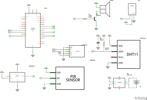
  • I designed the electronic schematic of my system using Fritzing. I pushed this schematic to my repository (https://github.com/alexandru-cohal/SmartExhibit). Below you can see it.


image

  • I implemented for each component a Sanity Check short program. I know from my previous projects that it is always useful to have such programs for testing different functionalities with each component in particular and also to verify that the respective component is actually working fine (for the moments when I am in doubt that something might have happened with the component or with the connection between the component and the board image)
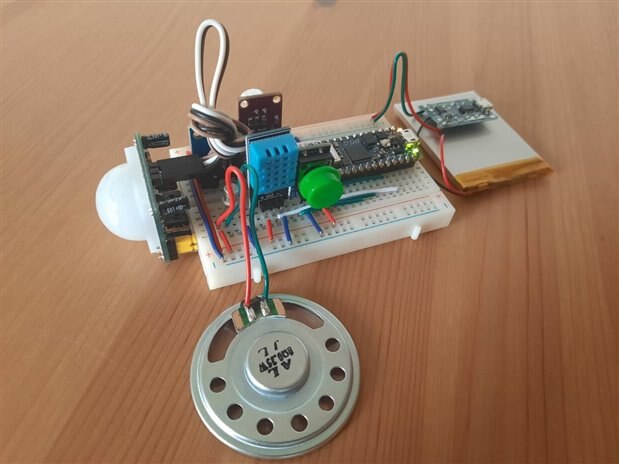
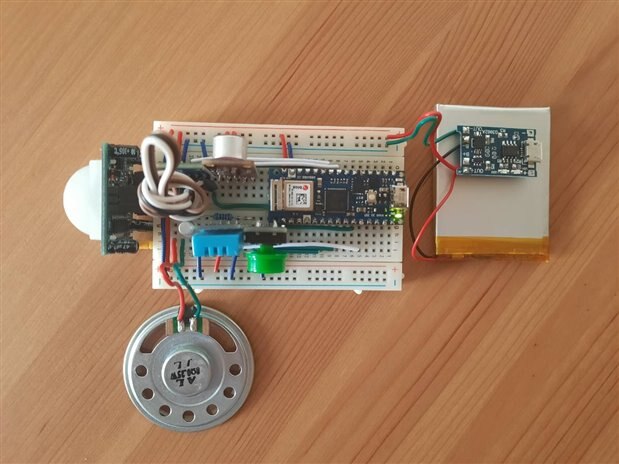
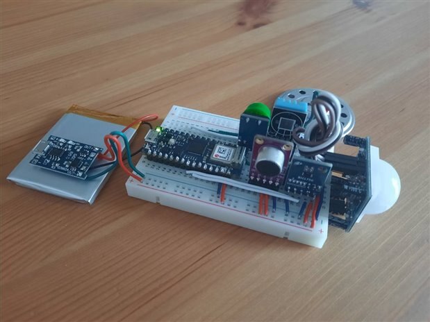
  • I connected all the components and the Arduino board together using a breadboard (I spent some time with my obsession of very clean and neat wirings but in the end it worth the effort image). Below you can see some photos of how the system looks. Pretty good, right? imageimage

image

image

image

  • I implemented a Sanity Check program for the whole system (the Arduino board + all the components). Again, this is for checking that all the components are working when connected together with the board at the same time and all the connections are fine (Rule number 1: There are never enough tests and checks image)
  • I pushed all the Sanity Checks programs to my repository (https://github.com/alexandru-cohal/SmartExhibit)
  • I kept my Trello board updated (https://trello.com/b/qwcDuQMy/smartexhibit).


I had a lot of fun playing with all the components and the Arduino Nano 33 IoT board but I am pretty sure that this is only the beginning image

  • Sign in to reply

Top Comments

  • alexandru.cohal
    alexandru.cohal over 4 years ago in reply to javagoza +2
    Hi! I was also a bit skeptical in the beginning if this will work or not. But until now, based on the tests I did, I didn't notice any problems (e.g. slowness, glitchy analogue pins) when I power the Arduino…
  • javagoza
    javagoza over 4 years ago +1
    Hi, I am curious. You're powering the board with only 3.7 volts. The MPM3610 Step Down Converter specifications indicate an input range between 4.5V and 21V. Have you noticed any problems in your tests…
  • alexandru.cohal
    alexandru.cohal over 4 years ago in reply to makervanlabs +1
    Thank you I will tell you the secret of how I managed to make the breadboard to look like this I used the wires from a general breadboard jumper wire set (like this one, for example) but I cut them in…
  • alexandru.cohal
    alexandru.cohal over 4 years ago in reply to makervanlabs

    Thank you image I will tell you the secret of how I managed to make the breadboard to look like this image I used the wires from a general breadboard jumper wire set (like this one, for example) but I cut them in order to be the perfect length and to stay parallel with the breadboard image


    I used the DHT11 temperature and humidity sensor which comes into a module with built-in filtering capacitor and pull-up resistor. So I didn't choose the values for the capacitor and resistor, they were already set image. I know that the pull-up resistors in the Arduino based projects should be around 10kΩ based on the general ranges of the current and voltage values but, to be honest, I never actually checked and calculated this. On this page I found a nice discussion about the range of values for the pull-up resistor.

    • Cancel
    • Vote Up +1 Vote Down
    • Sign in to reply
    • More
    • Cancel
  • makervanlabs
    makervanlabs over 4 years ago

    That breadboard really does look very neat   . I should seriously start working on my breadboard technique (which would benefit from buying proper wire as a start).


    Out of curiosity: I normally see a 10kΩ pullup on the DHT11's data line, any particular reason you went with less than that?

    • Cancel
    • Vote Up 0 Vote Down
    • Sign in to reply
    • More
    • Cancel
  • alexandru.cohal
    alexandru.cohal over 4 years ago in reply to javagoza

    Hi!


    I was also a bit skeptical in the beginning if this will work or not. But until now, based on the tests I did, I didn't notice any problems (e.g. slowness, glitchy analogue pins) when I power the Arduino Nano 33 IoT board with a LiPo 3.7V battery.


    Though, the battery's nominal voltage is 3.7 V, but when it is fully charged it reaches 4.2 V. Based on the MPM3610's datasheet, the range between 4.5V and 21V is the recommended input, so I guess it is not a strict limitation but a limitation for guaranteeing the functionality. These 2 aspects also count.


    I will do more tests with the whole range of the battery's voltage and I will see if I will notice some problems. I will also write here what will be the results image

    • Cancel
    • Vote Up +2 Vote Down
    • Sign in to reply
    • More
    • Cancel
  • javagoza
    javagoza over 4 years ago

    Hi,

    I am curious. You're powering the board with only 3.7 volts. The MPM3610 Step Down Converter specifications indicate an input range between 4.5V and 21V. Have you noticed any problems in your tests?


    image

    image

    Arduino nano 33 IoT Schematics:


    https://content.arduino.cc/assets/NANO33IoTV2.0_sch.pdf


    MPM3610 Step Down Converter Datasheet


    https://www.monolithicpower.com/en/documentview/productdocument/index/version/2/document_type/Datasheet/lang/en/sku/MPM3…

    • Cancel
    • Vote Up +1 Vote Down
    • Sign in to reply
    • More
    • Cancel
element14 Community

element14 is the first online community specifically for engineers. Connect with your peers and get expert answers to your questions.

  • Members
  • Learn
  • Technologies
  • Challenges & Projects
  • Products
  • Store
  • About Us
  • Feedback & Support
  • FAQs
  • Terms of Use
  • Privacy Policy
  • Legal and Copyright Notices
  • Sitemap
  • Cookies

An Avnet Company © 2025 Premier Farnell Limited. All Rights Reserved.

Premier Farnell Ltd, registered in England and Wales (no 00876412), registered office: Farnell House, Forge Lane, Leeds LS12 2NE.

ICP 备案号 10220084.

Follow element14

  • X
  • Facebook
  • linkedin
  • YouTube