


When designing the wearable device, we need to make some functional decisions, namely
- where to wear the device
- how to power the device (how many batteries? with which capacity?)
- how to keep costs down
Let' start from the most important topic: where the device should be wore to best detect the conditions the uniquely identifies a fall
Wearable position
The accelerometer and gyroscope are two types of sensors that are frequently used in fall detection. The project uses the Arduino Nano 33 IoT board, which is equipped a 6 DOF accelerometer, which measures the acceleration for each of the three axes x; y; z and the angular velocity around the three axes. The measured acceleration values are expressed in units corresponding to the acceleration of gravity. The value 1.0 corresponds to an acceleration of 9:8m/s22 in a given direction. Depending on the direction of movement, acceleration can have either a positive or negative value. The integrated gyroscope measures the angular velocity of the device for each of the axes. The measured values are expressed in radians per second and can be positive or negative depending on the direction of rotation.
Both types of sensors allow detecting various phases of the fall event and visualize the fall with the use of signal obtained from both sensor
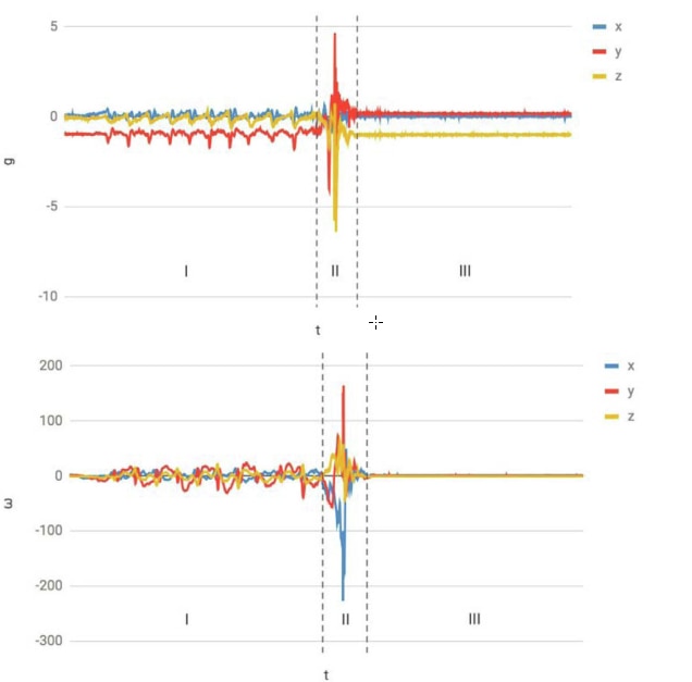
Typically, we can observe cyclic movements of the device in the first phase (phase I – performing the activity preceding the fall) corresponding to walking. Then, in the second phase (phase II – the fall), during the fall, we can see a rapid increase in both acceleration and angular velocity. In the third phase (phase III – after the fall), the person is at rest, and the readings from the sensors are fairly even, not counting the low-volume noise. In phase IV, which can happen after some time (therefore, not visualized), a person recovers, may get up alone or can be aided by a third party.
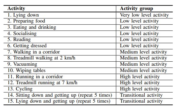
Since IMU provides the readings our analysis is based on, it's of paramount importance to place the accelerometer in the most suitable position, where the peculiar accelerations of a fall are sort of "amplified". There are many studies and proposals about the best position where a system that can detect body posture and movements should be placed. The most cited is the article "Sensor Placement for Activity Detection using Wearable Accelerometers". This work analyses the best sensor placement to detect the following activities. Activities have been grouped in five main categories, depending on the intensity of the activity itself
Data was collected by sensors placed in different positions
- ear
- arm
- wrist
- waist
- chest
- leg
Although significant care was taken to place all the wearable accelerometers at similar positions for all subjects, there were inevitable variations while attaching the sensors. Thus, the features extracted were chosen to be features that would not be highly affected by changes in orientation. These features include standard features that are generally used for activity recognition including variance, entropy and frequency features. The windows used for feature extraction were selected to be 5 sec each with no over-lap.
Collected data has been rated depending on the possibility to reliably detect the activity. The results are the following
- for "Very low level activities", wrist and ear worn sensors provides reasonable precisions
- for "Low level activities", waist sensor is the one providing maximal precision
- for "Medium level activities", chest and wrist sensor provide the best precision rates
- for "High level activities", the ear worn sensor collects the best data, because it measures changes in body posture while walking and running
- for "Transitional activities", the waist, chest and knee sensors reflect the parts of the body that are moving most
Since we want to discriminate a "transitional activity" (a fall) from any other activity, the options we have to evaluate are
- waist
- chest
- knee
I think the best option is to wear the device at the waist, because it can be kept in place by a simple clip (no belts or laces are needed) and, for this reason, it's easy to put on and off
As we will see in future posts, to develop this project I took a dataset of falls where both linear accelerations and angular velocities have been recorded and organized in a set of files that can be easily preprocessed and analyzed. Because such a dataset assumes that IMU axis are oriented in very specific directions, I will try to place Arduino Nano 33 IoT with the IMU oriented in that specific way. This requires the board to be placed as shown in pictures below
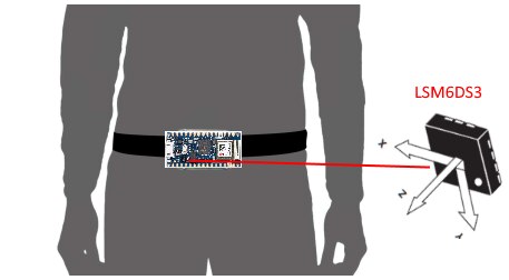
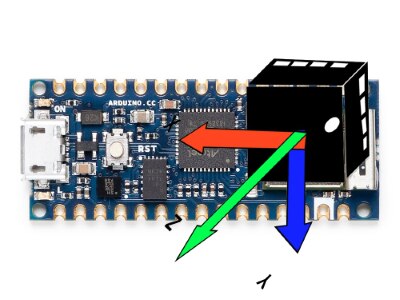
Note that the USB port faces the left (when seen from the front): this is to make the IMU axis to be oriented as expected.
This position has two more advantages
- I can use the built-in LED to signal the status of the device (if it is running properly or any error condition has been detected, if Wifi or BLE is connected, etc.) with no extra hardware. This is great both to keep final cost down and to save energy
- the reset button can be easily pressed. This is good in case of an activity has been mistakenly detected as a fall. User can press the reset button and cancel the alert message. This, again, is good to keep cost down because no external hardware has to be added
However, in future I think I will add an "emergency" button the senior may push in case he or she wants to report any emergency condition to the caregivers
Selecting the battery
The minimum requirement for a wearable should be to run on battery for at least one day, so one can plug the charger before going to bed and have the batteries fully charged the next morning.
Power consumption analysis
The first thing is to make an analysis of the current consumption of the Arduino Nano 33 IoT board for different use cases. I am particularly interested in the following scenarios
- I2C active: the I2C bus is used to communicate with the accelerometer, so I have to keep this peripheral active all the time
- WiFi active / inactive
- BLE active / inactive
- USB active / inactive: USB interface is required only to download and debug the application. In the final version, the USB version could be switched off to save energy
I measured current consumption with a multimeter with a resolution of 10uA. Here are the values I collected
| Condition | Power consumption (mA) min/max @ 6V |
|---|---|
| Empty sketch | 12,72 / 12,88 |
| LED Blink | 15,94 / 28.72 |
| Access to IMU | 13,78 / 13,86 |
| WiFi on (ping) | 33,16 / 71,08 |
| BLE on | 33,82 / 34,38 |
| WiFi + BLE on | 46,54 / 70,10 |
From this experiments, I can see that WiFi is very energy hungry. When tx-ing, power consumptions have peaks up to 70 mA and more. For this reason, the wearable I am going to build will have IMU always active and the connectivity will be switched on only when required. As a matter of fact, I don't need the Wifi or BLE connectivity to be active all the time: I need connectivity only to report a very rare event like a fall. So, to save power, I can keep the Wifi module off and switch it on only when I need to alert the caregivers.
A think I need to investigate is the reason why the "LED blink" test shows such a big difference between minimum and maximum current consumption. I suspect this is due to the delay() functions (which are nothing else than a busy loop) but I will make some further tests when I have some spare time
Power save modes
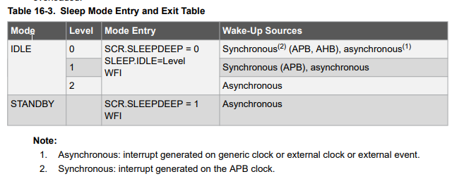
To further save the battery, I can eventually put the SAMD21 microcontroller (i.e. the microcontroller the Arduino Nano 33 IoT is built around) to sleep. SAMD21 has basically two power save modes
- standby mode: turns everything off, except low power clock and any module you specify to keep on (the peripherals configured with the RUNSTDBY bit set continue to run). Internal voltage regulators goes to low power mode
- idle mode: certain module continue to run, internal voltage regulator operates in normal mode
I will probably sample the IMU with a frequency of 50Hz (i.e. every 20 ms). I can put the SAMD21 processor to sleep for 20 ms, then wake it up to read the IMU, put it back to sleep for 20 ms (or slightly less than 20 ms) and so on. If reading the IMU takes 2 ms, and assuming that consumption in sleep mode is negligible when compared to the consumption in active mode, the average power consumption can be reduced by a factor of 10.
Arduino has a library for low-power modes. However, this library has a major limitation: the minimum sleep time is 1 second, even if the "sleep()" function takes a parameter expressed in milliseconds. This is because the LowPower library uses, internally another library (RtcZero) to handle the SAMD21 RTC.
The Real-Time Counter (RTC) is a 32-bit counter with a 10-bit programmable prescaler that typically runs continuously to keep track of time. The RTC will continue to operate in any sleep mode where the selected source clock is running. A counter in the RTC is increment at each clock cycle. When the RTC counter reaches a user-programmable value, an interrupt is generated and the microcontroller exits the current power mode to return to active mode. RTC can also generate periodic wakeup interrupts. The SAM21D has an internal low-power oscillator running at 32 kHz, which stays active in all power modes
The RTC can function in one of these modes:
- Mode 0 - COUNT32: RTC serves as 32-bit counter
- Mode 1 - COUNT16: RTC serves as 16-bit counter
- Mode 2 - CLOCK: RTC serves as clock/calendar with alarm functionality
RtcZero library only supports Mode 2 and it sets the prescaler to 1024, which leads to a resolution of 1 second. The prescaler is a value the RTC input clock frequency is divided by. For example, RTCZero library divides the input clock frequency (1024 Hz) by 1024. This means the RTC internal counters are increment every 1024 clock cycles, or, in other words, with a frequency of 1 Hz. The RTC input clock frequency comes from the SAMD21D's GCLK peripheral, which is configured to divide the 32 kHz by a factor of 32
Here is the code of RtcZero that configures GCLK to
- divide general clock source 2 as a source - GCLK_GENDIV_ID(2)
- divide the clock frequency by 32 (i.e. 2 ^ (4+1)) - GCLK_GENDIV_DIV(4)
GCLK->GENDIV.reg = GCLK_GENDIV_ID(2)|GCLK_GENDIV_DIV(4);
This is the code from the RtcZero library that shows how the RTC is configured
  tmp_reg |= RTC_MODE2_CTRL_MODE_CLOCK; // set clock operating mode
  tmp_reg |= RTC_MODE2_CTRL_PRESCALER_DIV1024; // set prescaler to 1024 for MODE2
  tmp_reg &= ~RTC_MODE2_CTRL_MATCHCLR; // disable clear on match

  //According to the datasheet RTC_MODE2_CTRL_CLKREP = 0 for 24h
  tmp_reg &= ~RTC_MODE2_CTRL_CLKREP; // 24h time representation
I wrote a specific function to put the SAMD in idle or standby mode and to make the RTC wake up the microcontroller every 20 ms. I will eventually make an Arduino library out of this function so that can be easily imported in an existing project
Here is how the function works
Configuring the clock
First of all, we need to configure the 32 kHz clock that is the input for the RTC peripheral module. As we already said, the RTC is typically clocked by the 1.024kHz output from the 32.768kHz High-Accuracy Internal Crystal Oscillator(OSC32K or OSCULP32K), because the 32 kHz clock is divided by a factor of 32 by settings the GENDIV.DIV register to 4 and the DIVSEL bit in the GCLK's GENCTRL register (the generic clock generator equals the clock source divided by 2^(GENDIV.DIV+1)).
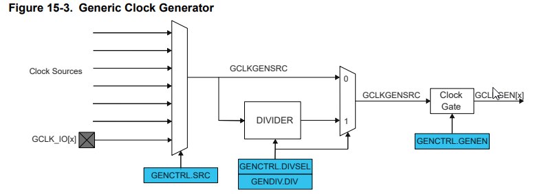
This lead to a timer resolution of 1 second. To get a better resolution, I divided the clock source by 1 by setting GENDIV.DIV to 1 and the DIVSEL bit to 0 (the generic clock generator equals the clock source divided by GENDIV.DIV)
GCLK->GENDIV.reg = GCLK_GENDIV_ID(2)|GCLK_GENDIV_DIV(0);
Next step is to select generic clock source n.2 and enable the clock
  GCLK->GENCTRL.reg = (GCLK_GENCTRL_GENEN | GCLK_GENCTRL_SRC_OSCULP32K | GCLK_GENCTRL_ID(2));
  GCLK->CLKCTRL.reg = (uint32_t)((GCLK_CLKCTRL_CLKEN | GCLK_CLKCTRL_GEN_GCLK2 | (RTC_GCLK_ID << GCLK_CLKCTRL_ID_Pos)));
Configuring RTC for MODE0
Configuration registers are enable-protected, meaning that they can only be written when the RTC is disabled (CTRL.ENABLE=0). So the first thing to do is disable the RTC
  // disable RTC
  RTC->MODE0.CTRL.reg &= ~RTC_MODE0_CTRL_ENABLE;
Next, we need to make a software reset of the RTC peripheral
RTC->MODE0.CTRL.reg |= RTC_MODE0_CTRL_SWRST;
Next, we can set the RTC for mode 0. A prescaler of 1 will be applied. The timer resolution is 30,5 microseconds
// configure RTC in mode 0 (32-bit)
RTC->MODE0.CTRL.reg |= RTC_MODE0_CTRL_PRESCALER_DIV1 | RTC_MODE0_CTRL_MODE_COUNT32;
Now let's set the value we want to counter be reach before the microcontroller is woken up.
When the RTC Operating Mode bits in the Control register are zero (CTRL.MODE=00), the counter operates in 32-bit Counter mode.
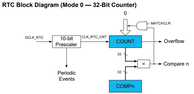
When the RTC is enabled, the counter will increment on every 0-to-1 transition of CLK_RTC_CNT. The counter value is continuously compared with the 32-bit Compare register (COMP0). When a compare match occurs, the Compare0 interrupt flag in the Interrupt Flag Status and Clear register (INTFLAG.CMP0) is set on the next 0-to-1 transition of CLK_RTC_CNT. If the Clear on Match bit in the Control register (CTRL.MATCHCLR) is '1', the counter is cleared on the next counter cycle when a compare match with COMP0 occurs. This allows the RTC to generate periodic interrupts or events with longer periods than are possible with the prescaler events.
After this explanation, we can say that, to have a 20 milliseconds sleep time, the comparison value to set is
20000 microseconds / 30,5 microseconds = 656
// initialize counter/compare values
RTC->MODE0.COUNT.reg = 0;
RTC->MODE0.COMP[0].reg = 656;
Now enable the CMP0 interrupt. This means an interrupt will be triggered when the counter reaches the COMP register
// enable the CMP0 interrupt in the RTC
RTC->MODE0.INTENSET.reg |= RTC_MODE0_INTENSET_CMP0;
If we now enable the RTC...
// enable RTC
RTC->MODE0.CTRL.reg |= RTC_MODE0_CTRL_ENABLE;
and go to sleep...
SCB->SCR |= SCB_SCR_SLEEPDEEP_Msk;
__DSB();
__WFI();
the application will be resumed in about 20 ms.
I wrote a very simple sketch to test a bare minimum skeleton of the final application. In this sketch, I simply read the IMU and put the SAMD21 microcontroller to sleep for 20 ms. Since it's important to learn from past errors, I added a 20 seconds delay at startup in order to have time to download a different application from Arduino IDE in case of issues. Here is the full code
#include <Arduino.h>
#include <Arduino_LSM6DS3.h>

int status = 0;

void setup() {
  pinMode(LED_BUILTIN, OUTPUT);

  // put your setup code here, to run once:
  GCLK->GENDIV.reg = GCLK_GENDIV_ID(2)|GCLK_GENDIV_DIV(0);
  GCLK->GENCTRL.reg = (GCLK_GENCTRL_GENEN | GCLK_GENCTRL_SRC_OSCULP32K | GCLK_GENCTRL_ID(2));
  GCLK->CLKCTRL.reg = (uint32_t)((GCLK_CLKCTRL_CLKEN | GCLK_CLKCTRL_GEN_GCLK2 | (RTC_GCLK_ID << GCLK_CLKCTRL_ID_Pos)));

  IMU.begin();
  delay(20000);
}

void loop() {
  float aX, aY, aZ, gX, gY, gZ;

  // put your main code here, to run repeatedly:
  RTC->MODE0.CTRL.reg &= ~RTC_MODE0_CTRL_ENABLE; // disable RTC
  RTC->MODE0.CTRL.reg |= RTC_MODE0_CTRL_SWRST;

  // configure RTC in mode 0 (32-bit)
  RTC->MODE0.CTRL.reg |= RTC_MODE0_CTRL_PRESCALER_DIV1 | RTC_MODE0_CTRL_MODE_COUNT32;

  // initialize counter/compare values
  RTC->MODE0.COUNT.reg = 0;
  RTC->MODE0.COMP[0].reg = 656;

  // enable the CMP0 interrupt in the RTC
  RTC->MODE0.INTENSET.reg |= RTC_MODE0_INTENSET_CMP0;

  // enable RTC
  RTC->MODE0.CTRL.reg |= RTC_MODE0_CTRL_ENABLE;

  SCB->SCR |= SCB_SCR_SLEEPDEEP_Msk;
  __DSB();
  __WFI();

  digitalWrite(LED_BUILTIN, HIGH);
  if (IMU.accelerationAvailable() && IMU.gyroscopeAvailable()) {
    // read the acceleration and gyroscope data
    IMU.readAcceleration(aX, aY, aZ);
    IMU.readGyroscope(gX, gY, gZ);
  }
  status = !status;
  digitalWrite(LED_BUILTIN, LOW);
}
As you can see from the video, current consumption drops to an average of 5 mA after the startup delay 20 seconds. The minimum value detected by the multimeter is 2.44 mA, which is, in my opinion, the current absorbed by the ICs on the Arduino Nano 33 IoT board and, as such, this should be considered the limit to current consumption
Battery selection
To be on the safe side, I will consider an average current consumption of 20 mA and, assuming that we want the wearable to work for 24 hours between recharges, a battery of at least 500 mAh is required. I have a couple of 3.7 V Li-Ion batteries I recycled from some old smartphones. The capacity is 2100 mAh: that's enough to power the device for about 4 days.
I tried to find a reliable solution to power the Arduino Nano 33 IoT with a single 3.7 V battery, but that was going to be completely unreliable. First, battery voltage may go up to 3.8 V, which is higher than the maximum voltage the SAMD CPU and uBlox Wifi module are rated for. Further more, the uBlox WiFi module requires a minimum of 3 V and battery voltage may drop below that level very quickly.
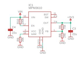
So the solution is to connect the two batteries in series and power the Arduino Nano 33 IoT board from the Vin pin, which is connected to an MPM3610 synchronous step-down converter. This solution should allow the wearable to work even if the voltage of the battery pack drops to 4.5 V, which is minimum input voltage the MPM3610 is rated for
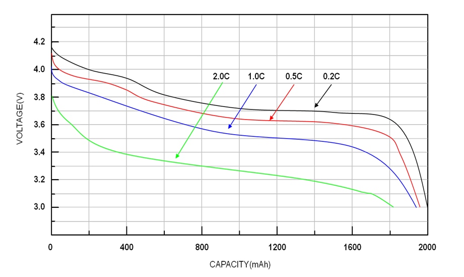
Each battery could drop to a mere 2.25 V, which is well below the minimum voltage Li-Ion are typically considered completely discharged when voltage is 3V (see curve below, which show the typical discharge curve for a 2000 mAh Li-Ion battery, from fully charged -at 4.2V- to fully discharged -at 3.0 V). This means that we can use all the batteries capacity without and risk of dropping below the minimum input voltage allowed by the MPM3610 step-down converter
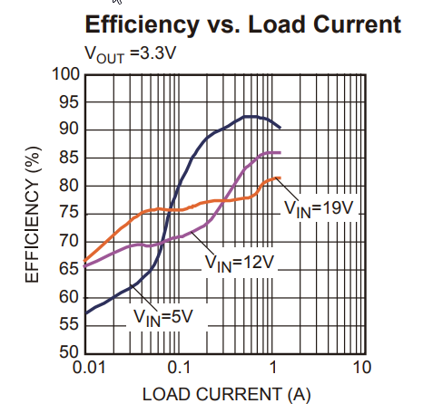
After all, as one can see from the step-down converter datasheet, the efficiency of the step-down converter is not so bad: at 200 mA and 7 V, the efficiency is about 80% (this is just my educated guess: the correct value is somewhere between the black line and the purple line)
Other considerations
As a side note, It's a shame the Arduino Nano 33 IoT does not have the INT signals of the LSM6DS3 connected (see schematic below)
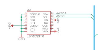
The LSM6DS3 has a really great set of features, including the ability to generate an interrupt when a specific configurable event is detected. Events the LMS6DS3 can detect include
- free-fall
- wakeup
- 6D orientation
- tap and double-tap sensing
- activity / inactivity recognition
Should the INT signal be connected, I would have been able to put the SAMD11 microcontroller to sleep for extended period of time (for example during the night or when the person is sitting or) and let the SAMD21 to be woken up by the LSM6DS3 when activity only when activity is detected.
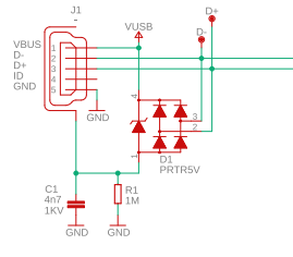
Another point to note is that connecting the power supply to the USB port is different, because the VBUS pin of the USB port is connected to a Zener diode (I think it's a 5V Zener diode), which causes an extra current to flow through the diode and thus leads to an higher power consumption
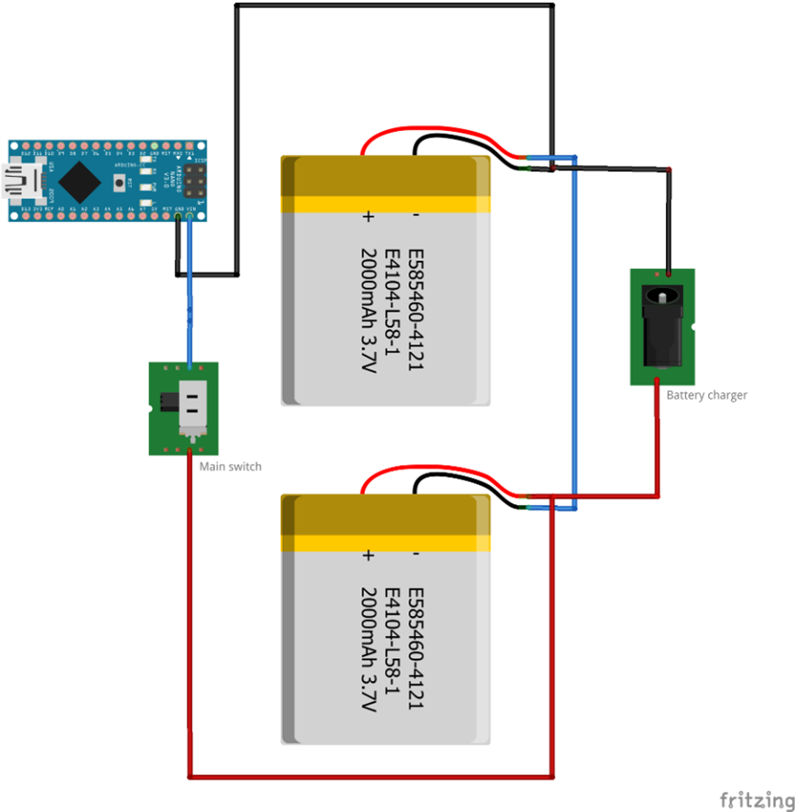
Connection schematic
The connections are super easy. There are just two 3.7 V Li-Ion batteries in series which power the Arduino Nano 33 IoT board, a switch and a female strip where the battery charger will be connected
Building the wearable
Why not use recycled material to build the wearable sensor? This it the very short bill of materials required
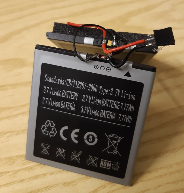
- two 3.7V 2100 mAh Lion batteries. I had two batteries recovered from some old smartphones that were perfect for the purpose
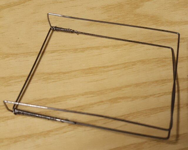
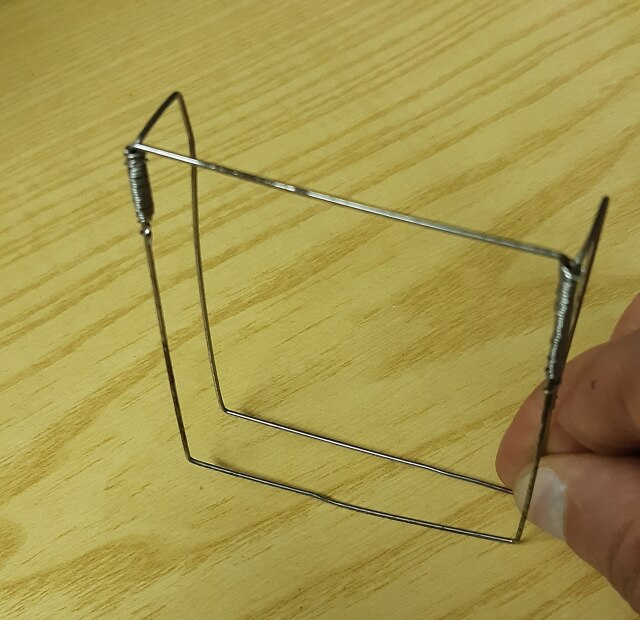
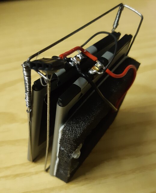
- harmonic steel wire to build the cradle for the batteries and the electronic board. The cage will be U-shaped in order to be easily clipped to the belt or to the trousers
- some foam to protect the Arduino Nano 33 IoT board. In this case, I reused the foam that I found in the shipping box of the Arduino Nano 33 IoT itself
- to connect the battery charger, I used a female strip header with three poles. Vcc is connected to the middle pin and the ground is connected to both the lateral pins, to that you can connect the charger without any risk to invert polarity
- a sock to cover everything up
Regarding the required tools, I think you will just need
- pliers, to shape the harmonic steel
This is the U-shaped cage (or cradle) made from a single piece of harmonic steel. An extra bar has been added to make the cradle more rigid and to provide support for the connector for the battery charger. The U-shaped cradle has been thought to be clipped to trousers waist or belts
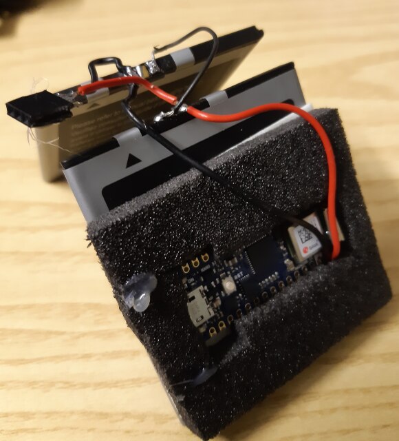
This is the board protected by the foam and fixed one of the battery with double sided tape
The Arduino Nano 33 IoT will face forward. Note that the USB connector must be n the left (when looked from the front) to maintain the correct orientation of the IMU axis
And here are the batteries mated with the cradle
| Previous post | Source code | Next post |
|---|---|---|
| ACE - Blog #1 - Project description | https://github.com/ambrogio-galbusera/ace2.git | ACE - Blog #3 - Sending notifications |
Top Comments