


In this post I will explained how ACE can send notifications to the rescuers in case of fall
Twilio
I want ACE to send notification through SMS because this is probably the most reliable way of sending alarm notifications: they work wherever there is a 2G coverage, and are not affected by application out-of-services (for example, I experienced Whatsapp black-out even recently). Also, receiving SMS is nowadays a "abnormal" event, because we are mainly focused on messages and notification coming from social applications. So an SMS is more likely to be noticed and read promptly.
Since the Arduino Nano 33 IoT does not have a modem on-board, we must rely on an external service. I selected Twilio because we can send SMS worldwide and provides a convenient trial account. So the first thing is to register on Twilio and request a phone number (number with US prefix are free, other prefixes may be charged)
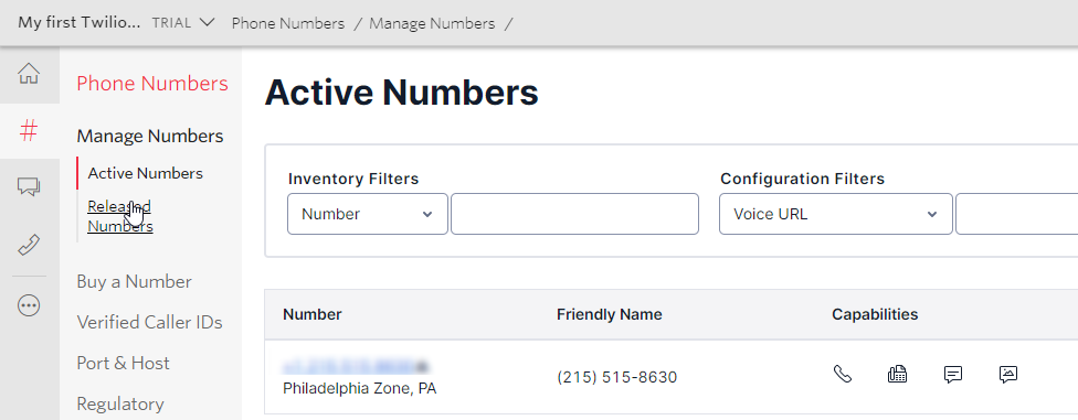
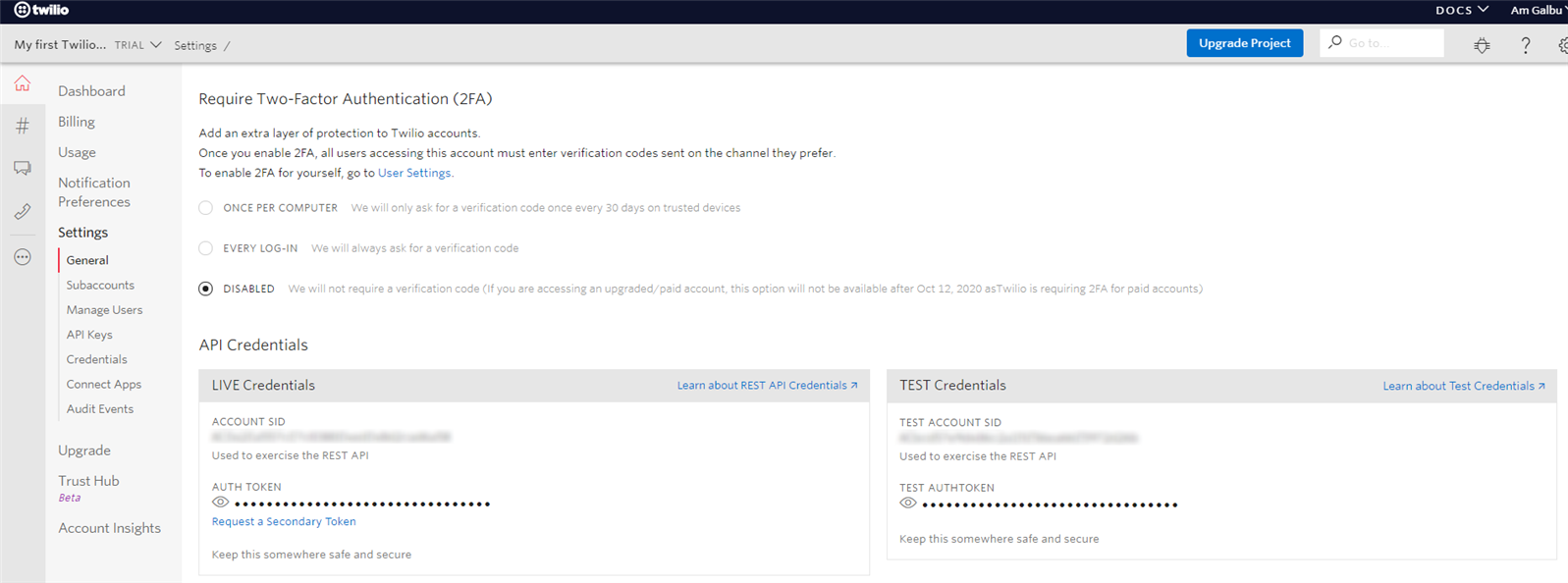
Next step, is to find the Account SSID and the Account token. Both are required to invoke Twilio's APIs
Sending SMS through REST API
I will invoke Twilio's API using plain simple C code.
Twilio allows only HTTPS connections. For this reason, we need to use class WiFiSLLClient class, which is included in WiFiNINA library. The URL we need to connect to is api.twilio.com, port number is 443
  const char* host = "api.twilio.com";
  const int   httpsPort = 443;

  WiFiSSLClient client;
  if (!client.connect(host, httpsPort)) {
  }
To send a messages, we have to make an HTTP POST request. The body of the request is prepared by this code
  // URL encode our message body & picture URL to escape special chars
  // such as '&' and '='
  String encoded_body = urlencode(message_body);

  String post_data = "To=" + urlencode(to_number) + "&From=" + urlencode(from_number) + \
                     "&Body=" + encoded_body;
Next, we have to prepare the HTTP POST request header. Twilio requires Basic authentication, which means that username and password are base64-encoded and included in the HTTP request header. To create the basic authentication data, the _get_auth_header is invoked
String auth_header = _get_auth_header(account_sid, auth_token);
The _get_auth_header uses base64 encoding to encode the string <account sid>:<auth_token>.
  snprintf(toencode, toencodeLen, "%s:%s", user.c_str(),vpassword.c_str());

  char encoded[toencodeLen];
  base64_encode(encoded, toencode, toencodeLen - 1);
  String encoded_string = String(encoded);

  return "Authorization: Basic " + encoded_string;
Note that base64 encode and decode functions are not included in the Arduino standard libraries, but you can download file base64.h and base64.c from this repository and copy to the sketch folder. The only change is to remove the "PROGMEM" directive from base64.c file
The HTTP POST can now be created...
  String http_request = "POST /2010-04-01/Accounts/" +
                        String(account_sid) + "/Messages HTTP/1.1\r\n" +
                        auth_header + "\r\n" + "Host: " + host + "\r\n" +
                        "Cache-control: no-cache\r\n" +
                        "User-Agent: Arduino Nano 33 IoT\r\n" +
                        "Content-Type: " +
                        "application/x-www-form-urlencoded\r\n" +
                        "Content-Length: " + post_data.length() + "\r\n" +
                        "Connection: close\r\n" +
                        "\r\n" + post_data + "\r\n";
... and sent
client.println(http_request);
Smartphone connectivity
SMS are sent using Twilio REST API when a Wifi network is available. When the elder is not at home or whenever a Wifi network is not working properly, ACE relies on connectivity provided by a smartphone to send notifications. The wearable device sends alarm notifications to the smartphone app using BLE and the app, in turn, sends an SMS to the caregivers
BLE on Arduino
Implementing the BLE connectivity on Arduino is very easy thanks to the ArduinoBLE library. In your sketch, you have just to define services and characteristics
BLEService posService("95ff7bf8-aa6f-4671-82d9-22a8931c5387");
BLEFloatCharacteristic posX("95ff7bf8-aa6f-4671-82d9-22a8931c5387", BLERead | BLENotify);
BLEFloatCharacteristic posY("f49caa00-17f8-4e92-b5fd-d27137ca4515", BLERead | BLENotify);
BLEFloatCharacteristic posZ("84f9b003-6d14-44d7-8db1-d574d29c10c3", BLERead | BLENotify);
initialize the BLE
  if(!BLE.begin()) {
    // Failed to initialize BLE, blink the internal LED
    Serial.println("AceBle: Failed initializing BLE");
    return false;
  }

  // Set advertised local name and services UUID
  BLE.setDeviceName("Arduino Nano 33 IoT");
  BLE.setLocalName("ACE");

  posService.addCharacteristic(posX);
  posService.addCharacteristic(posY);
  posService.addCharacteristic(posZ);
  BLE.addService(posService);


  hbService.addCharacteristic(hb);
  BLE.addService(hbService);

  // Start advertising
  BLE.advertise();
and update accelerometer values every time a new accelerometer value is available
  // Write values on BLE
  posX.writeValue(x);
  posY.writeValue(y);
  posZ.writeValue(z);
Smartphone application
A custom Android application has been developed to connect to the wearable device.
I started the development of this application from the experiences I made during the "1 Meter of Pi challenge", so you can find useful information about implementation of BLE connectivity here and here.
However, this application has some new features, namely
- it subscribes to BLE notifications instead of continuously asking for data. This means the Arduino Nano 33 IoT board will send data to the smartphone as soon as new data is available
- it shows a realtime graph of the accelerometer values. This can be very useful during application development. A "ruler" has also been developed, to measure peak values and time distances
Getting BLE notifications
To enable BLE notifications, we have to invoke the setCharacteristicNotifcation function of the BluetoothGatt class. The setCharacteristicNotifcation takes two parameters
- the BluetoothGattCharacteristic whose notifications we want to enable/disable
- a boolean that says whether we want to enable or disable notifications
The second step is to set the value of the only BluetoothGattDescriptor with the value ENABLE_NOTIFICATION_VALUE
All the code is invoked in the onServiceDiscovered callback, which is invoked by the BluetoothManager when a new BLE device has been discovered
@Override
public void onServicesDiscovered(BluetoothGatt gatt, int status) {
   for (BluetoothGattService service : gatt.getServices()) {
     if ((service == null) || (service.getUuid() == null)) {
       continue;
  }

   if (BleUuid.POS_SERVICE.equalsIgnoreCase(service.getUuid().toString())) {
     List<BluetoothGattCharacteristic> chars = service.getCharacteristics();
     for (BluetoothGattCharacteristic characteristic : chars) {
       if (BleUuid.POS_VALUE.equalsIgnoreCase(characteristic.getUuid().toString())) {
         mConnGatt.setCharacteristicNotification(characteristic, true);

         List<BluetoothGattDescriptor> descriptors = characteristic.getDescriptors();
         descriptors.get(0).setValue(BluetoothGattDescriptor.ENABLE_NOTIFICATION_VALUE);
         mConnGatt.writeDescriptor(descriptors.get(0));
      }
    }
  }

   else if (BleUuid.ALARM_SERVICE.equalsIgnoreCase(service.getUuid().toString())) {
     List<BluetoothGattCharacteristic> chars = service.getCharacteristics();
     for (BluetoothGattCharacteristic characteristic : chars) {
       if (BleUuid.ALARM_VALUE.equalsIgnoreCase(characteristic.getUuid().toString())) {
         mGattAlarmChar = characteristic;
       }
     }
  }
  }
After this initialization, out application should start getting values from the BLE peripheral. When a new value is received, function onCharacteristicChanged of the BluetoothGattCallback interface is invoked
Here, we simply invoke method drawSurfaceView.drawPoints to draw the new values on the real-time chart
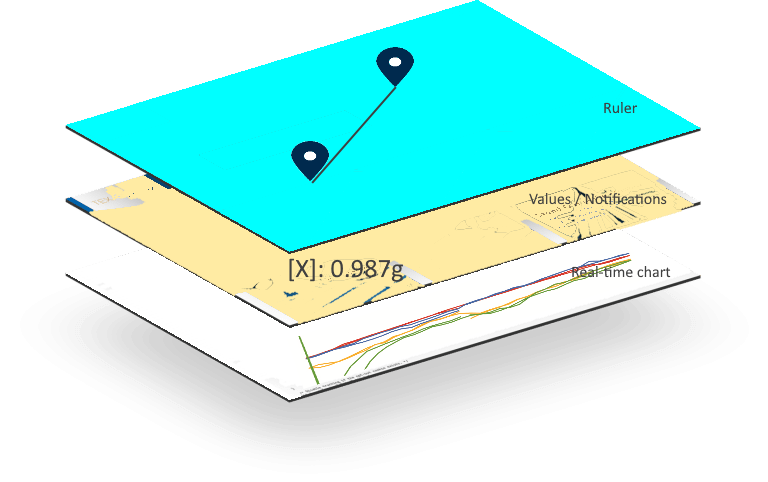
Real-time chart
Values received from oscilloscope are visualized in a real-time chart. This is probably not very useful for the final user, but it's absolutely invaluable when evaluating the performances of the fall detection algorithm
Real-time has been created by leveraging the Android's SurfaceView class. The SurfaceView class is used to create custom views because it gives you full access to the underlying Canvas object.
Basically, the Canvas is a class that performs 2D drawing onto the screen. So a canvas is an empty space where the developer can draw everything he wants. The SurfaceView provides convenient access to the canvas through the SurfaceHolder class. The main role of this class is to provide a controlled access to canvas, so that the application can prepare an hidden canvas asynchronously in a dedicated a thread and leave the UI responsive to the user inputs. When canvas is ready, application notifies the Android's graphics system which, in turns, renders the canvas content on the screen
In this application, I created three overlapping SurfaceView objects:
- one to draw the real-time chart
- one to draw values and notifications (for example, in case of a fall)
- one to draw the ruler
Probably this concepts are more clear if you go through a demo video
Building the real-time chart and all the other features is just a matter of properly composing the very basic drawing functions of the Canvas class (drawLine, drawRect. etc)
You have only to keep in mind two things:
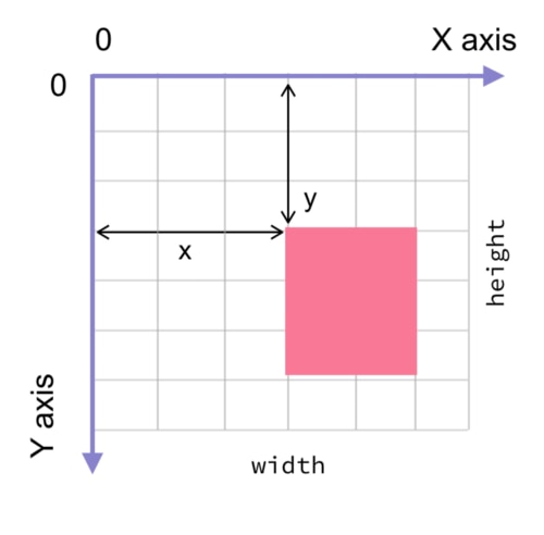
- the canvas coordinate system. The coordinate system of the Android Canvas starts in the top left corner. The Y axis is positive downwards and the X axis is positive towards the right. All element drawn on a canvas are placed relative to the origin point at coordinate (0, 0)
- canvas draw commands will draw over previously drawn items. The last draw command will be the topmost item drawn onto your canvas. So it's important to order draw primitives to have the foremost elements drawn after all other elements.
That said, the first think is to create the layout with the three overlapping SurfaceView objects
<RelativeLayout xmlns:android="http://schemas.android.com/apk/res/android"
   xmlns:tools="http://schemas.android.com/tools"
   android:layout_width="match_parent"
   android:layout_height="match_parent"
   android:orientation="vertical"
   tools:context=".DeviceActivity">
<SurfaceView
   android:id="@+id/rulerView"
   android:layout_width="match_parent"
   android:layout_height="match_parent" />
  <SurfaceView
   android:id="@+id/tagView"
   android:layout_width="match_parent"
   android:layout_height="match_parent" />
  <SurfaceView
   android:id="@+id/surfaceView"
   android:layout_marginTop="60px"
   android:layout_width="match_parent"
   android:layout_height="match_parent" />
</RelativeLayout>
You have three SurfaceView and their Canvas. Before drawing, you have to lock the Canvas
canvas = drawViewHolder.lockCanvas(new Rect(x - deltaX, 0, x + 100, height));
Note that you can lock just one section of the Canvas (for example, in the previous code, we are locking a vertical band of 100 pixels. This clears the area on the right of the last value drawn and creates a sort of "oscilloscope" effect).
Next step is to draw a line from the last point we draw to the new point. This is accomplished by the following code
canvas.drawColor(Color.WHITE);
for (int i=0; i<NUM_CHANNELS; i++) {
  pen.setColor(COLORS[i]);
  canvas.drawLine(x - deltaX, lastYs[i], x, ys[i], pen);
}
When done, you have to unlock the Canvas
drawViewHolder.unlockCanvasAndPost(canvas);
Here we called unlockCanvasAndPost, which unlocks the canvas and notifies the Android's graphic system that a buffer is ready to be rendered on the screen
If you are interested in how the real-time chart has been created, you can have a look at file DrawSurfaceView.java.
A notable mention goes to this fantastic library I integrated in the source code and that makes you create rounded filled polygons very easily
Sending the SMS
When the ACE wearable device is connected to the smartphone, it relies to the smartphone itself to send the SMS to the caregivers in case of emergency. Sending SMS is quite easy in Android because Android provides a very handy service called SmsManager
SmsManager smsManager = SmsManager.getDefault();
smsManager.sendTextMessage(RESCUE_NUMBER, null, text, mSentIntent, mDeliveredIntent);
The problem here is to detect whether the SMS has been delivered successfully to the operator's SMS center (SMSC). The "life" of an SMS goes through different phases, namely
- Sent: the mobile device has sent the SMS to the SMSC and the SMSC has confirmed that it has received the SMS
- Delivered: the mobile device has received a SMS-DELIVER message (delivery notification) from the SMSC, which typically means that the SMS has reached the destination mobile. Note however that, sometimes, SMSCs will say that an SMS as delivered when it has actually just been relayed to another SMSC and not the destination mobile device.
To implement this checks, we can leverage the Android's BroadcastReceiver features. The BroadcastReceiver is a dormant component that listens to system-wide broadcast events (aka intents int the Android jargon). When one of this events occur, it notifies the application(s) that have registered itself to receive that specific event. Applications typically extend the BroadcastReceiver class to create a custom implementation of the onReceive method, where application logic required to handle the event is executed. As one can read in the Android developers documentation, method sendTextMessage has two parameters called sentIntent and deliveryIntent. These are exactly the events the BroadcastReceiver can handle. When the SmsManager's sendTextMessage method is called, the SmsManager sends out the SMS message and notifies applications that SMS has been sent by broadcasting the Intent passed as sentIntent.
What we have to in our application is to
1. create the Intents
mSentIntent = PendingIntent.getBroadcast(DeviceActivity.this, 0, new Intent(SENT), 0);
mDeliveredIntent = PendingIntent.getBroadcast(DeviceActivity.this, 0, new Intent(DELIVERED), 0);
2. register to receive that same Intents
registerReceiver(mDeliveredSMSRcvr, new IntentFilter(DELIVERED));
registerReceiver(mSentSMSRcvr, new IntentFilter(SENT));
SENT and DELIVERED can be any strings that uniquely identify the event. In this case I set their values to
private final String SENT = "SMS_SENT";
private final String DELIVERED = "SMS_DELIVERED";
Last step, is to override onReceive method of the abstract class BoradcastReceiver class to implement the application-specific logic required to handle the events
class SentSMSBroadcastReceiver extends BroadcastReceiver {

   @Override
   public void onReceive(Context arg0, Intent arg1) {
   switch (getResultCode()) {
   case Activity.RESULT_OK:
     Toast.makeText(DeviceActivity.this, "SMS sent",
     Toast.LENGTH_SHORT).show();
     drawSurfaceView.updateCountDownStatus(0, DrawSurfaceView.COUNT_STATUS_SENT);
     break;
   case SmsManager.RESULT_ERROR_GENERIC_FAILURE:
     Toast.makeText(DeviceActivity.this, "Generic failure",
     Toast.LENGTH_SHORT).show();
     break;
   case SmsManager.RESULT_ERROR_NO_SERVICE:
     Toast.makeText(DeviceActivity.this, "No service",
     Toast.LENGTH_SHORT).show();
     break;
   case SmsManager.RESULT_ERROR_NULL_PDU:
     Toast.makeText(DeviceActivity.this, "Null PDU",
     Toast.LENGTH_SHORT).show();
     break;
   case SmsManager.RESULT_ERROR_RADIO_OFF:
     Toast.makeText(getBaseContext(), "Radio off",
     Toast.LENGTH_SHORT).show();
     break;
    }
  }
}

class DeliveredSMSBroadcastReceiver extends BroadcastReceiver {
   @Override
   public void onReceive(Context arg0, Intent arg1) {
   switch (getResultCode()) {
   case Activity.RESULT_OK:
     Toast.makeText(DeviceActivity.this, "SMS delivered",
     Toast.LENGTH_SHORT).show();
     drawSurfaceView.updateCountDownStatus(0, DrawSurfaceView.COUNT_STATUS_DELIVERED);
   break;
   case Activity.RESULT_CANCELED:
     Toast.makeText(DeviceActivity.this, "SMS not delivered",
     Toast.LENGTH_SHORT).show();
     break;
   }
  }
}
As you can see, in this case I just handle the scenario when the SMS is sent and delivered successfully. The error conditions should be handled as well. In case of error the application could retry to send the SMS until the SMS itself is reported as successfully delivered to the SMS centre
| Previous post | Source code | Next post |
|---|---|---|
| ACE - Blog #2 - Building the wearable | https://github.com/ambrogio-galbusera/ace2.git | ACE - Blog #4 - The neural network |
