


Now that I have a much better understanding of how to “talk” to the MAX40080 and the performance limitations of the combination with Python and the Raspberry Pi 3 B running 64-bit Raspberry Pi OS Lite, it would be nice to get an understanding of how well the MAX40080 itself performs in the Mikroe Current 6 Click implementation. To do this, I challenged it with my test equipment to verify its measurement accuracy and noise characteristics.
Table of Contents
Update
Please note that the cause of the unusual results was identified and new results are presented in Blog #5. The methodology presented here is correct and also applies to Blog #5, thus the original blog posting is preserved in its entirety but does not reflect the expected performance of the MAX40080 and the Mikroe Current 6 Click board.
Test Program and Expectations
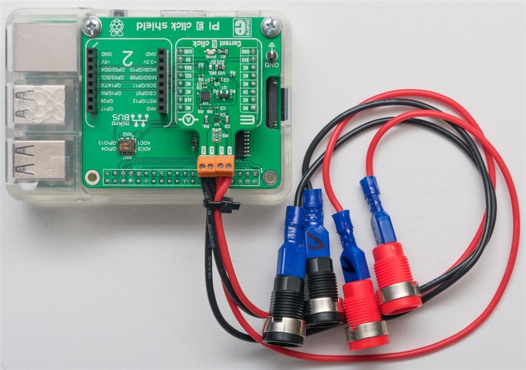
In order to run the tests, the Click was attached to short 16AWG silicone wire pigtails, ending in spade crimps that were attached to shrouded banana sockets which were used to connect standard 4mm banana test leads to the test equipment.
The original test program was then modified to incorporate SCPI commands to drive the test instrument, either to sweep through the range of currents or voltages, or to generate a fixed level. In the case of a sweep, the MAX40080 was configured to operate at 1MSa/s, 128-sample averaging, of which 1024 samples for each point were analysed for the mean, maximum and minimum. For the case of a fixed level noise measurement, the mid-point of the range was generated by the test instrument and the MAX40080 was configured to operate at 500Sa/s, with no averaging, of which 1 million data points were captured for analysis. An example of the former program is listed below, but as modifications are trivial for the other cases, I will not list all the variations of the program.
import RPi.GPIO as GPIO
from smbus import SMBus
import time
import pyvisa

GPIO.setwarnings(False)
GPIO.setmode(GPIO.BOARD)
GPIO.setup(8,GPIO.OUT)
GPIO.output(8,GPIO.HIGH)

i2cbus = SMBus(1)
i2caddress = 0x21
reglist = [0x00,0x02,0x04,0x05,0x06,0x07,0x08,0x0A,0x0C,0x0E,0x10,0x14]
regwidth = [2,2,1,1,1,1,2,2,2,2,4,1]

resource_manager = pyvisa.ResourceManager()
ins_k2450 = resource_manager.open_resource('TCPIP0::192.168.80.19::inst0::INSTR')
ins_k2450.timeout = 20000

print("Gough's MAX40080 Verification Program")
print("-----")
print("Initial Register Values:")
for i in range(0,len(reglist)) :
  regres = i2cbus.read_i2c_block_data(i2caddress,int(reglist[i]),int(regwidth[i]))[::-1]
  res = 0
  for x in range(0,len(regres)) :
    res = res << 8 | regres[x]
  print("Register "+hex(reglist[i])+": "+hex(res))
print("---")
print("Disable PEC ...")
i2cbus.write_i2c_block_data(i2caddress,0x00,[0x00,0x00,0xB7]) # PEC Byte is ITU
print("Configure active mode ...")
i2cbus.write_i2c_block_data(i2caddress,0x0A,[0x00,0xB4]) #34
i2cbus.write_i2c_block_data(i2caddress,0x00,[0x43,0x5E])
i2cbus.write_i2c_block_data(i2caddress,0x0A,[0x00,0x34])
print("---")
print("Running Register Values:")
for i in range(0,len(reglist)) :
  regres = i2cbus.read_i2c_block_data(i2caddress,int(reglist[i]),int(regwidth[i]))[::-1]
  res = 0
  for x in range(0,len(regres)) :
    res = res << 8 | regres[x]
  print("Register "+hex(reglist[i])+": "+hex(res))
print("---")
print("Opening a logfile ...")

f = open("exwcsaverif-"+str(time.time())+".csv","a")

print("Setting Up - K2450")
print(ins_k2450.query("*IDN?")) # Assume SCPI command set
ins_k2450.write("OUTP 0")
ins_k2450.write("DISP:DIG 6")
ins_k2450.write("SOUR:FUNC CURR")
ins_k2450.write("SOUR:CURR:RANG 1")
ins_k2450.write("SOUR:CURR:VLIMIT 2")
ins_k2450.write("SOUR:CURR 0")
ins_k2450.write("OUTP 1")
ins_k2450.query("*OPC?")

input("Press any key to begin ...")

for i in range (0,10001) : # Positive Currents
  ins_k2450.write("SOUR:CURR "+str(i/10000.0))
  ins_k2450.query("*OPC?")
  time.sleep(0.05)
  rb = ins_k2450.query_ascii_values("READ?")[0]
  mcount = 0
  mcum = 0
  mmax = -4096
  mmin = 4096
  mavg = 0
  # Flush FIFO
  i2cbus.write_i2c_block_data(i2caddress,0x0A,[0x00,0xB4])
  i2cbus.write_i2c_block_data(i2caddress,0x0A,[0x00,0x34])
  i2cbus.read_i2c_block_data(i2caddress,0x0c,2)
  while(mcount < 1024):
    fifod = i2cbus.read_i2c_block_data(i2caddress,0x0c,2)[::-1]
    val = 0
    for x in range(0,2) :
      val = val << 8 | fifod[x]
    dvalid = val & 0x00008000
    dsign = val & 0x00001000
    dvalue = val & 0x00000FFF
    if dsign != 0 :
      dvalue = dvalue - 4096
    if dvalid != 0 :
      mcount = mcount + 1
      dvalue = dvalue / 4095.0
      mcum = mcum + dvalue
      if dvalue > mmax :
        mmax = dvalue
      if dvalue < mmin :
        mmin = dvalue
  mavg=mcum/mcount
  f.write(str(time.time())+","+str(rb)+","+str(mavg)+","+str(mmax)+","+str(mmin)+"\n")
  f.flush()

for i in range (0,-10001,-1) : # Negative Currents
  ins_k2450.write("SOUR:CURR "+str(i/10000.0))
  ins_k2450.query("*OPC?")
  time.sleep(0.05)
  rb = ins_k2450.query_ascii_values("READ?")[0]
  mcount = 0
  mcum = 0
  mmax = -4096
  mmin = 4096
  mavg = 0
  # Flush FIFO
  i2cbus.write_i2c_block_data(i2caddress,0x0A,[0x00,0xB4])
  i2cbus.write_i2c_block_data(i2caddress,0x0A,[0x00,0x34])
  while(mcount < 1024):
    fifod = i2cbus.read_i2c_block_data(i2caddress,0x0c,2)[::-1]
    val = 0
    for x in range(0,2) :
      val = val << 8 | fifod[x]
    dvalid = val & 0x00008000
    dsign = val & 0x00001000
    dvalue = val & 0x00000FFF
    if dsign != 0 :
      dvalue = dvalue - 4096
    if dvalid != 0 :
      mcount = mcount + 1
      dvalue = dvalue / 4095.0
      mcum = mcum + dvalue
      if dvalue > mmax :
        mmax = dvalue
      if dvalue < mmin :
        mmin = dvalue
  mavg=mcum/mcount
  f.write(str(time.time())+","+str(rb)+","+str(mavg)+","+str(mmax)+","+str(mmin)+"\n")
  f.flush()

f.close()
ins_k2450.write("OUTP 0")
ins_k2450.close()
GPIO.cleanup()
The test equipment used to challenge the MAX40080 was the Keithley 2450 SMU which I had previously RoadTested. This would be good to exercise the full voltage range and the 1A current range. For the higher current range of 5A, I used the Rohde & Schwarz NGM202 PSU which is a specialty, high-precision power supply. As these units have relatively small errors (1A – 0.03%, 5A – 0.05%, 36V – 0.015%) for sourcing compared to the current sense amplifier set-up (0.2%), their contributions to errors are deemed negligible and have been ignored.
The MAX40080 is listed in the datasheet as having an ultra-low 5µV input offset voltage and very-low 0.2% gain error which sounds pretty impressive. An offset of 5µV would translate into an error of 0.5mA given a 10mΩ resistor, thus the current measurement specification could be (theoretically) expressed as 0.2% ± 0.5mA. However, these headline values deserve a little more scrutiny, as the maximum input offset of CSA+ADC is listed at 55µV, while the gain error of CSA+ADC is listed as 1.05% when considering the full temperature range. Considering very unfavourable conditions, this would translate to a 1.05% ± 5.5mA which is perhaps less impressive. This still only considers the contribution of the IC itself, as the external current shunt provided will have an impact on accuracy as well. Voltage measurements will not have the contribution of a shunt, but is listed with a maximum offset voltage of 35mV when including the voltage buffer and ADC, while the gain error is listed with a maximum of 1.2%, also including the voltage buffer and ADC. Considering that this is a digital current-sense amplifier, I feel that focusing on values that do not include the ADC contribution seems moot and even borderline misleading, as the chip is not providing an analog output independent of the ADC so any inaccuracies due to the ADC will be incurred by the user.
To better understand the contribution of the shunt resistor to the resulting error, I contacted Mikroe technical support via their contact form, and within a day, was told the shunt resistor was a Susumu RL2720WT-R010-F. This appears to be a 1W resistor with a 1% tolerance and a 0 to +350ppm per °C temperature coefficient. As a result, with current measurements, it seems that the error induced from the shunt resistor and its self-heating will probably dominate over the intrinsic error of the MAX40080. The only way around this is to specify a more expensive resistor, perhaps with a 0.1% tolerance and even lower temperature coefficient.
As a result, based on the datasheet and information I have to hand, I am expecting the current sensing accuracy to be around 1% to 2%, and voltage sensing accuracy to be about 0.2% to 1.2%.
Current Measurement Accuracy – 1A Range
The first test analyses the current measurement accuracy in the 1A range.

The result is somewhat unexpected. First concentrating on the “average” of 1024 readings in blue, the error seems to mostly be gain error with some non-linearity around +800mA. The maximum and minimum values of the 1024 readings, however, seem to imply a systematic under-reading of the current magnitude which increases with the magnitude of the current. Therefore, you are more likely to read a value below that of the actual current than you are to read a value above the actual current. This behaviour is not expected.

Focusing on the average of 1024 readings (which, each are an average of 128 values), the result is mostly linear. The gain error measures about 1.71% with an offset of 0.2mA which is within the range I was expecting, but reminds us that the solution’s accuracy is more than just the accuracy of the integrated circuit.
Current Measurement Accuracy – 5A Range

Repeating the same for the 5A range, it was interesting to see the same systematic under-reading behaviour recurring. There is also a slight non-linearity around +4A as well, suggesting this behaviour is not a result of oscillation of test equipment but perhaps represents an actual error contribution from the chip itself.

Again, the result is roughly linear although it seems to flatten at the extremes which may be due to heating of the shunt resistance and the thermal coefficient. The gain error appears to be about 1.5% with an offset of 2.3mA which is still within the range of my expectations.
Voltage Measurement Accuracy
For all the strangeness that I had observed with current measurements, to see the same sort of code operate on voltage measurements produce such a steady result somewhat vindicates my suspicion that the results I was seeing with the current measurements are actually real.
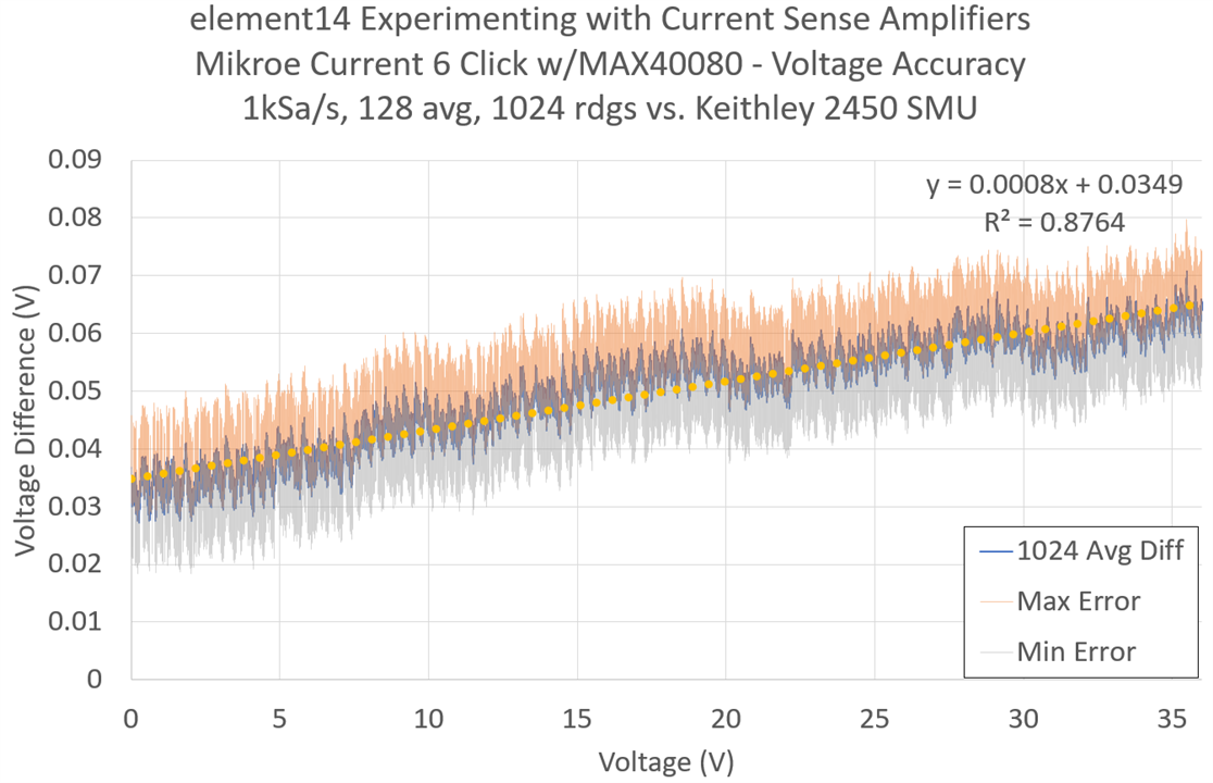
On the whole, voltage measurements were extremely accurate with a linear fit of average result giving an incredible 0.08% gain error with a 34.9mV offset which is just fractionally below the maximum offset stated in the datasheet. A small amount of this may have come from thermal EMFs, with a greater portion of up to 10mV due to offset from the SMU. This result is excellent.
Current Measurement Noise – 1A Range
Current measurement noise was measured to see just how “quiet” the readings are. The less noisy they are, the more likely a system can capture small changes in current with greater certainty.

Testing at the 1A range with a current of 0.5A in the middle of the range resulted in this rather noisy signal. The readings seemed to span from about 0.42A to 0.52A which is quite a bit of noise.

In spite of this, zooming into a 1s snippet of time, it seems the correct reading is being read most of the time, but there is a burst of downward blips, at a rate of 3-4Hz which are corrupting the reading. This is almost certainly what is the cause of the observed asymmetry in error readings. At first, I thought this may have been a result of enabling “both Voltage and Current” mode, but in my case, the configuration of the FIFO’s Store_IV value is clearly 00 which is current only.

As a result, the reading histogram reflects exactly what was observed earlier in terms of likelihood of under-reading versus over-reading the actual value.
Current Measurement Noise – 5A Range

Stepping up to 5A range, using a middle-range 2.5A test current, the readings ranged from about 1.9A to 2.6A which is still a significant amount of noise. My expectation was that the lower amplification necessary in this range may have reduced the amount of noise in the output readings, but this does not appear to be the case.

The same 3-4Hz downward blips were observed in the measured data when zoomed into 1s of the recording. The cause is not understood at this time.

The histogram shows a similar shape overall, again indicating a greater likelihood of under-reading rather than over-reading the current.
As a final attempt to remove any doubt surrounding the current measurement results, I did try repeating the test with the bus at 100kHz and at 400kHz and received nearly identical results. The strange “blips” do not seem to be caused by communication errors, but perhaps may be caused by other factors that only affect the current reading. What those may be are still unclear, but its effect is to cause a nearly-periodic under-reading of current magnitude.
Voltage Measurement Noise
As evidenced previously, voltage measurements seemed quite accurate with a very small range of noise values. A closer look at the noise performance appears as follows –

It seems that the readings mostly clustered around four ADC values with a few spikes up and down which appear to be random noise. Perhaps it is a result of the USB supply to the Raspberry Pi, internal clock jitter affecting the ADC or external EMI affecting the input. Regardless, the result is still quite good.

Zooming in to just one second of data, there was no clear periodicity or pattern to the signal, so it seems unlikely that mains noise would be a significant contributor to the variations seen. Regardless, the voltage measurements seem very reliable, but this is not the primary use of a current-sense amplifier!
Conclusion
In this chapter, I tried to characterise the performance of the Mikroe Current 6 Click containing the MAX40080 which proved interesting. While the MAX40080 itself headlines very attractive offset and gain-error values, the datasheet’s maximum values when inclusive of the ADC are much less attractive. From my perspective, as there is no analog output involved, values exclusive of the ADC are of limited value to the designer and could be a bit misleading. The solution itself will also suffer from the tolerance of the shunt resistor used for current measurement. In this case, through directly contacting Mikroe, it was determined to be a 1% tolerance with a 0 to +350ppm per °C temperature coefficient.
Measured current accuracy in the 1A range had a gain error of 1.71% with an offset of 0.2mA, at 5A this was 1.5% with an offset of 2.3mA which was within my expectations and understanding. The voltage measurement accuracy was significantly better with a gain error of 0.08% and a 34.9mV offset, a significant chunk of the latter could be attributed to the test equipment itself.
Unfortunately, the current measurement behaviour seems problematic with a significant amount of noise that often results in under-reading of the current magnitude. This seems to be concentrated in “blips” that occur at a 3-4Hz interval, the cause of which is not understood. The fact that the voltage measurements did not have this characteristic suggests it is not a code data handling problem, and the mode was verified to be “current only”. Re-attempting the experiment at lower bus rates of 400kHz and 100kHz was still showing the same distribution of values and under-reading, although at the slower bus rate, FIFO overflows were also occurring resulting in lost values and thus “irregularities” in the dip frequency as a result. All of this suggests to me that the reading noise and behaviour observed is characteristic of this particular unit’s operation, rather than something I have done wrong, but I am still willing to be proven wrong.
Another finding was the non-linearity in current measurement around the 0.8A/4A region where it seems the under-reading dips were more significant resulting in the average reading being pulled down. This did not affect negative current of the same magnitude, however.
If time permits, I will try to find some good applications for the MAX40080, however, the noise seen in the measurements really does put a bit of a spanner in the works for my original proposal, as the noise is significant and makes it harder to use the current sense amplifier for current profiling where small subtle changes may happen. If time permits, I’ll still give it a try, but otherwise I might also try using the Click on a different platform in case I can eke out some more performance or improve noise results.
---
This is part of the Experimenting with Current Sense Amplifiers Design Challenge – A Current-Sensing PSU Upgrade Blog Series:
- Blog #1: A Current-Sensing PSU Upgrade - Introduction
- Blog #2: A Current-Sensing PSU Upgrade - Unboxing
- Blog #3: A Current-Sensing PSU Upgrade – Setting Up
- Blog #4: A Current-Sensing PSU Upgrade – Accuracy & Noise Performance
- Blog #5: A Current-Sensing PSU Upgrade – Arduino Gets Involved, Ground to Raspberry Pi … Alien Signal Identified!
- Blog #6: A Current-Sensing PSU Upgrade – PSU Logging, CSA & FastLog Comparison, a Sound Check & an Overall Summary

