


While I had intended for a steady stream of blogs to feature in this particular design challenge, a last-minute pile-up of commitments saw me being sent on a 4.5-hour trip interstate for over a week to perform some data collection. After returning home, I had all the usual post-holiday things to do, along with another review which I’m working on concurrently. Nevertheless, I still found some time to return to the project, although I’m probably firmly out-of-the-running when it comes to the prizes.
Now that the unit has been unboxed and plugged together, now comes the tricky part – setting things up to get it all running.
Table of Contents
Setting Up the Raspberry Pi
The world is suffering a bit of a Raspberry Pi shortage at the moment, but thankfully, I have a Raspberry Pi 3 B board which I have borrowed from my Octopi setup for this project.
Using a fresh microSD card, I imaged the latest version of Raspberry Pi OS manually. For this, I chose to use Raspberry Pi OS Lite 64-bit, released 4th April 2022, as I did not require any desktop and intended to work heedlessly as much as possible.
Because of updates to security, set-up is easiest performing it interactively as the default username and password is no longer used. Unfortunately, I encountered an issue with the graphics hanging and not showing the terminal correctly, which needed some editing of the config.txt file to change the video driver to vc4-fkms-v3d. Walking through the setup process interactively, I was able to setup a “pi” user account anyway with a password of my own choosing.
From here, it is always a good idea to have it connected to the network. In case of using Wi-Fi, this also means setting the Wi-Fi Country and entering the SSID/passphrase which can be done through raspi-config. It is also good to set the language locale, time-zone, enable SSH and I2C access and hostname as well. Next step is to ensure the software is up to date, using the good ‘ol sudo apt-get update, sudo apt-get upgrade and sudo apt-get dist-upgrade.
Once that is done, then we can install the necessary packages. For convenience, I decided to install python3-pip, python3-smbus, i2c-tools, git and screen. As I will also be working with networked SCPI instruments, I also ran pip3 install pyvisa pyvisa-py.
Where’s the Software?
Unfortunately, while the Mikroe Current 6 Click has some software support in the form of a C-based library, it is mostly intended for use with their development boards, which we are not using. We could derive some inspiration from the code, but I felt this would take more time than it is worth.
Being rather late to the game, I noticed that misaz had developed a Python library in addition to a C-based library. For newcomers, perhaps this is the easiest way to get started, although I only discovered this after I had started my own hacky efforts. In trying it, I found some strange behaviour especially with seemingly incorrect handling of negative current values. This is no surprise – Python is absolutely annoying with its “arbitrary” width “integer” values such that simple masks and shifts don’t have the intended sign-extension effect. UPDATE: See comments as it has now been fixed!
As a bit of a hacky weekend job, I decided to go direct from the datasheet and schematics and try and work this out on my own.
Getting Up and Running
The first step in getting up and running was to enable the current sense amplifier itself.
#!/bin/sh
echo "8" > /sys/class/gpio/export
echo "out" > /sys/class/gpio/gpio8/direction
echo "1" > /sys/class/gpio/gpio8/value
echo "8" > /sys/class/gpio/unexport
The enable line is connected to a GPIO, so I wrote a short shell script to enable it. Upon executing this, it then became possible to see the MAX40080 on the bus using i2cdetect.
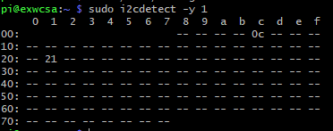
From there, it was a case of writing code to try and read all the registers, configure the registers and read values from the FIFO. I managed to write a simple logger, although the configuration values are computed manually from the datasheet. As I was aiming for performance (with Python – the irony!) and couldn’t care less about flexibility, this would be a quick and dirty way forward. As usual, the endianness needs to be taken into consideration.
import RPi.GPIO as GPIO
from smbus import SMBus
import time

#GPIO.setwarnings(False)
GPIO.setmode(GPIO.BCM)
GPIO.setup(8,GPIO.OUT)
GPIO.output(8,GPIO.HIGH)

i2cbus = SMBus(1)
i2caddress = 0x21
reglist = [0x00,0x02,0x04,0x05,0x06,0x07,0x08,0x0A,0x0C,0x0E,0x10,0x14]
regwidth = [2,2,1,1,1,1,2,2,2,2,4,1]

print("Gough's MAX40080 Test Program")
print("-----")
print("Initial Register Values:")
for i in range(0,len(reglist)) :
  regres = i2cbus.read_i2c_block_data(i2caddress,int(reglist[i]),int(regwidth[i]))[::-1]
  res = 0
  for x in range(0,len(regres)) :
    res = res << 8 | regres[x]
  print("Register "+hex(reglist[i])+": "+hex(res))
print("---")
print("Disable PEC ...")
i2cbus.write_i2c_block_data(i2caddress,0x00,[0x00,0x00,0xB7]) # PEC Byte is ITU
print("Configure active mode ...")
i2cbus.write_i2c_block_data(i2caddress,0x0A,[0x00,0xB4]) # Clear FIFO
i2cbus.write_i2c_block_data(i2caddress,0x00,[0x03,0x5E])
i2cbus.write_i2c_block_data(i2caddress,0x0A,[0x00,0x34]) # Enable FIFO
print("---")
print("Running Register Values:")
for i in range(0,len(reglist)) :
  regres = i2cbus.read_i2c_block_data(i2caddress,int(reglist[i]),int(regwidth[i]))[::-1]
  res = 0
  for x in range(0,len(regres)) :
    res = res << 8 | regres[x]
  print("Register "+hex(reglist[i])+": "+hex(res))
print("---")
print("Opening a logfile ...")

f = open("exwcsalog-"+str(time.time())+".csv","a")

''' # This block of code relies on the FIFO Status Register
while(True):
  statusr = i2cbus.read_i2c_block_data(i2caddress,0x02,2)
  fifon = statusr[1]
  fifox = (statusr[0] & 0x80)
  if fifon > 0 or fifox :
    if fifox :
      i2cbus.write_i2c_block_data(i2caddress,0x02,statusr)
      fifon = 64
    while fifon > 0 :
      fifod = i2cbus.read_i2c_block_data(i2caddress,0x0c,2)[::-1]
      val = 0
      for x in range(0,2) :
        val = val << 8 | fifod[x]
      dvalid = val & 0x00008000
      dsign = val & 0x00001000
      dvalue = val & 0x00000FFF
      if dvalid == 0 :
        print("Invalid Data!")
      else :
        if dsign != 0 :
          dvalue = dvalue - 4096
        f.write(str(time.time())+","+str(dvalue)+","+str(fifon)+","+str(fifox)+"\n")
      fifon=fifon-1
    f.flush()
'''
# This block of code doesn't give a toss about the FIFO Status Register
while(True):
  fifod = i2cbus.read_i2c_block_data(i2caddress,0x0c,2)[::-1]
  val = 0
  for x in range(0,2) :
    val = val << 8 | fifod[x]
  dvalid = val & 0x00008000
  dsign = val & 0x00001000
  dvalue = val & 0x00000FFF
  if dvalid != 0 :
    if dsign != 0 :
      dvalue = dvalue - 4096 # Two's complement
    f.write(str(time.time())+","+str(dvalue)+"\n")
    f.flush()

GPIO.cleanup() # Won't be called though ...
My code takes care of the GPIO enable line, enumerates the initial register values, performs some configuration, clears the FIFO, opens a log file and has two different ways of handling the chip. One is just to read the status register and only read values from the FIFO when there are values to be read. The shorter and perhaps more optimal way seems to be to hammer the FIFO instead, only accepting values when the 15th bit (Data Valid) is set.

The FIFO itself is 64-cells deep, with a single overflow bit and a “warning” level as well. A quirk is that the number of values is zero when overflow occurs – this is noted in the datasheet and my code can handle that but it was initially confusing. While the FIFO is nice to have, there does not seem to be a facility to run repeated burst-reads of the FIFO register and ensure we are getting valid FIFO values. The datasheet seems to recommend against performing long transactions entirely, which is not ideal as this leads to additional bus overhead in needing a start-address-register cycle for each FIFO value read.

Tuning for Performance!
While the code works, it’s hardly optimal as it stands. For one, we’re not even pushing the I2C as fast as it can go. The chip supports the 3.4MHz HS mode, but unfortunately, I haven’t got anything that will support that as it’s an entirely different beast, being a current-mode bus and neither does the level-shifting hardware on the Click. By default, we are running at 100kHz standard mode speeds, but we can easily push this to 400kHz fast mode on most microcontrollers and even 1MHz fast mode plus.
In order to do this, a modification is needed to the config.txt file to add the following line:
dtparam=i2c_baudrate=1000000
A reboot is necessary to apply this setting. Unfortunately, after rebooting, I found a number of errors which stopped the I2C bus from working at all.

Curiously, a full shutdown, removing power and plugging back in again seems to avoid this error on a speed change.
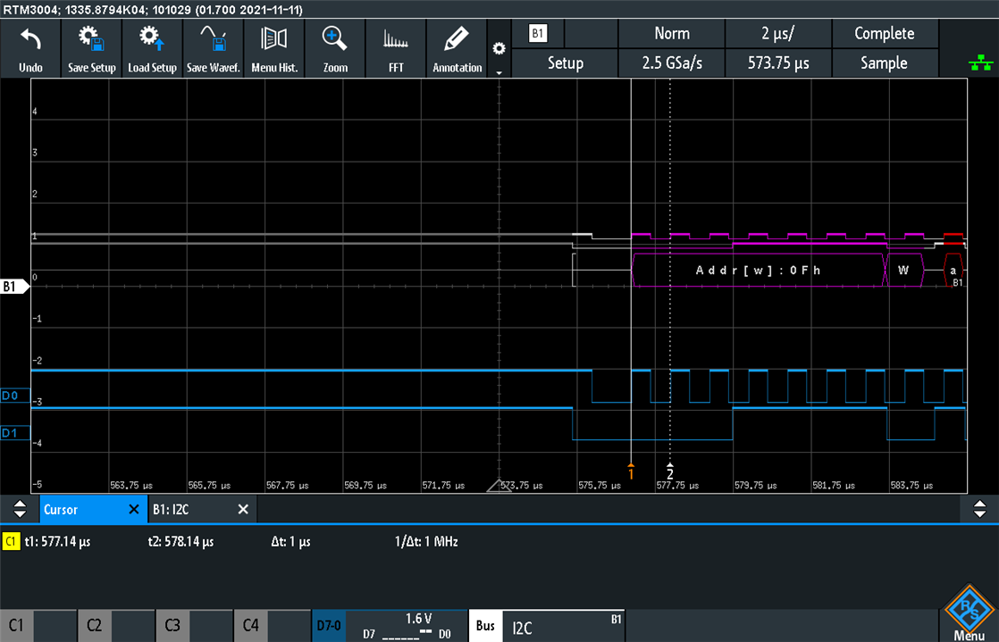
Using the digital probe on the Rohde & Schwarz RTM3004, I verified that we were indeed signalling at 1MHz.
The MAX40080 also features the SMBus ability of using a packet error check byte with each transmission. This can be important in ensuring data integrity as the I2C bus does not feature any error detection or correction – things will just silently go flaky. Unfortunately, this adds one extra byte to every transaction which means more bus time, while also requiring some “horsepower” to compute the CRC-8 (ITU variant, which I discovered the hard way) that is used.
To do this, my Python code basically sets the configuration register to all zeroes with a pre-computed PEC byte. I initially didn’t realise the PEC byte covers address and register bytes and had no idea which variant of CRC-8 was used, so I had to do some head-scratching to figure it out. Thankfully, the chip will NACK anything that doesn’t make sense, but after disabling the PEC byte, we can basically skip the error checking with the potential for occasional errors creeping in. As our bus length is short and well-controlled, this was a risk I was willing to take.
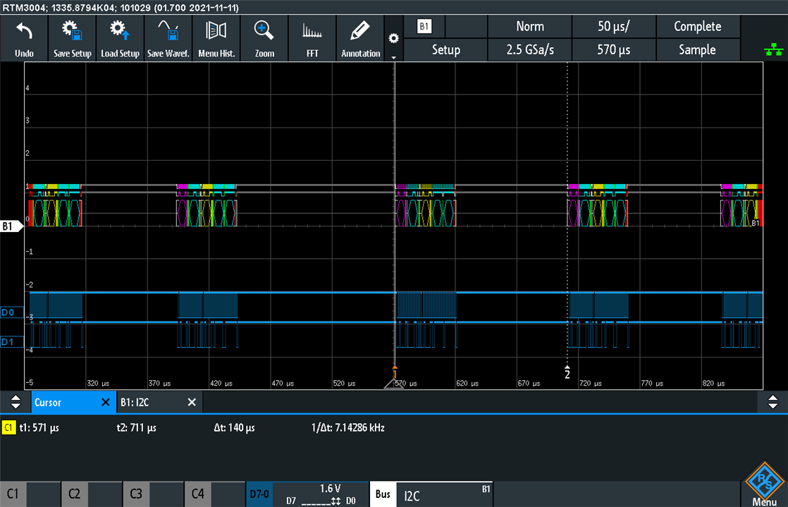
Unfortunately, with the FIFO status checking version of the code, we were only hitting the registers at a rate of about 7kHz which is way too slow for my liking.
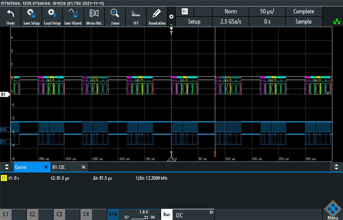
With the non-status-checking version that just looked at the data valid bit, it was possible to increase this to a rate of 12kHz. This was better, but still meant that the second-lowest sample rate of 15kHz could not be achieved!
So, while Table 9 in the datasheet has a nice colour-coded table that implies that we can probably push even 18.75kSa/s of readings, in reality, this is also constrained by the time taken by the host to process the data and turnaround the next transaction. Using a microcontroller with separate offload hardware or FPGA would probably be able to meet this level of performance, but the Raspberry Pi seems a bit distracted and Python is not ideal for performance either.
In a last-ditch attempt to push a bit more performance, I tried overclocking the I2C bus even further, but by 1.05MHz, I was already getting corrupted readings and unacknowledged writes, so that is not a possibility.
Instead, doing a bit of thinking, I settled on the optimum mode as the highest sample rate of 1MSa/s with the maximum averaging filter of 128 samples, knocking the actual data output rate to 7.8125kSa/s. This should be within the ability of the Raspberry Pi based on the experiments above, but would maximise the CSA’s ability to measure and average out noise at the cost of energy consumption (which is not particularly an issue in this application).
Testing out this sample rate, I captured around a minute of data, dividing the number of data points recorded by the amount of time elapsed based on the Raspberry Pi’s internal clock read out through the time.time() function. The result measured 7492Sa/s, which is not the 7812.5Sa/s expected but not that far from it either (-4.1%). For now, this seems good enough for me! Perhaps if I were not logging as ASCII-based CSV, the Raspberry Pi could save some time as well.
Conclusion
It took a bit of work, but it seems that it is not all that difficult to work with the MAX40080 just on the datasheet alone. The datasheet is relatively short and dense, with some things needed to be worked out by trial-and-error. In the end, I did manage to get there in terms of writing some software that worked for my proposed case where performance was a paramount concern. In spite of the CSA’s high sample rate capabilities, the I2C bus connectivity proves to be an Achille’s heel as there are not many HS-mode capable controllers and fast-mode-plus while offering decent bandwidth on-paper for some of the sample rates, actually becomes insufficient when data processing delays are taken into account. For the maximum data output, perhaps a dedicated hardware offload or FPGA with HS-mode is desirable. However, the high sample rates are undeniably an advantage when it comes to ensuring more stable measurements at the cost of power consumption, as it enables the use of an internal averaging filter of up to 128 samples.
In the next blog, I will be seeing just how accurate this Click module using the MAX40080 is at measuring currents and voltages, by challenging it with my SMU and PSU arsenal.
---
This is part of the Experimenting with Current Sense Amplifiers Design Challenge – A Current-Sensing PSU Upgrade Blog Series:
- Blog #1: A Current-Sensing PSU Upgrade - Introduction
- Blog #2: A Current-Sensing PSU Upgrade - Unboxing
- Blog #3: A Current-Sensing PSU Upgrade – Setting Up
- Blog #4: A Current-Sensing PSU Upgrade – Accuracy & Noise Performance
- Blog #5: A Current-Sensing PSU Upgrade – Arduino Gets Involved, Ground to Raspberry Pi … Alien Signal Identified!
- Blog #6: A Current-Sensing PSU Upgrade – PSU Logging, CSA & FastLog Comparison, a Sound Check & an Overall Summary


