This is my last extra credit blog.
Solar Module Assembly
I've had all of the solar panel components hooked up and running with the exception of operating with the actual load of the CM4 and sensor assemblies. The two final integration steps are to package the battery and charge controller for outdoor use and then connection to the enclosure electronics.
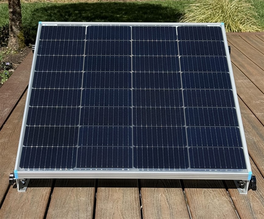
Here is the bifacial solar panel attached to the tilt mounting brackets. It is springtime so I'll probably set the panels pretty much as shown with a south facing orientation and 30-45 degrees inclination from horizontal. Maybe some position tweaking as I get data. For summer I may switch to fully horizontal, but there should be enough sun intensity that it probably won't matter.
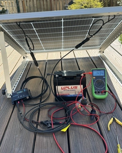
The backside of the panel with short cable pigtails with quick disconnect IP67 rated MC4 connectors for +/- terminals. I have a 10 foot extension cable to the charge controller (way too long for an outdoor installation but I may want to use it with the charge controller, battery, and load indoors also). The battery has an SAE 2 pin quick disconnect cable assembly which is also IP67 rated. The load +/- and the RS-232 TX/RX will be on a 4 conductor cable wired directly to the 4 pin Amphenol connector mated to the enclosure panel connector.
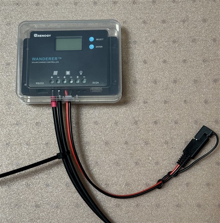
This is my initial test setup. The charge controller will be mounted in a ventilated plastic case attached to one of the brackets on the underside of the panel. The battery will be housed in a plastic ammo case.
Here is a quick video of the charge controller sequencing through its status displays.
It is displaying
- Solar Panel Voltage
- Solar Panel Current
- Battery Voltage
- Battery Current
- Controller Load Mode - 15 means that it requires manual turn on
- Load is off so there is no Load Voltage/Current displayed
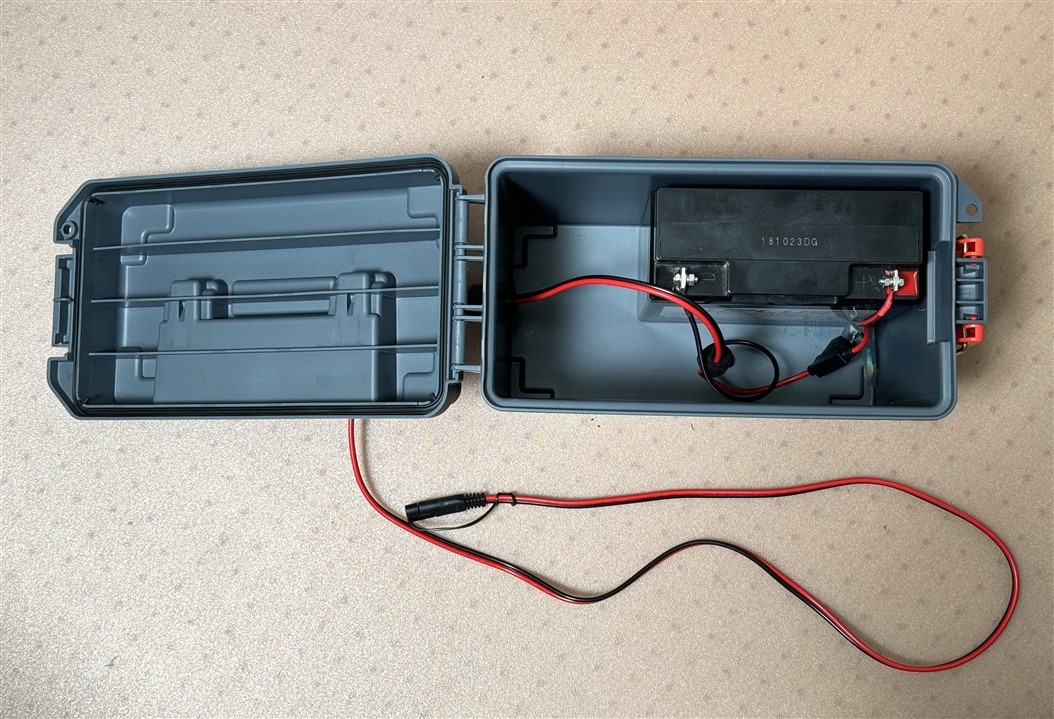
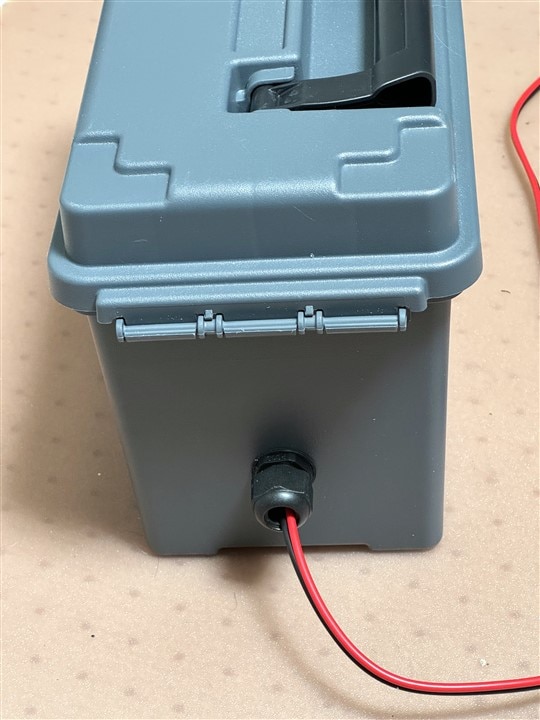
Here is the battery in the waterproof ammo case. The case is a bit oversize because smaller cases could not fit the battery height. It will be handy to carry other accessories in case I need to make the setup portable in an emergency. The cable gland is also a bit oversize because I didn't want to cut off and reterminate the waterproof connector or fuse holder. It was easier to get one large enough to pass the SAE connector and to pack the gland opening to seal the cable..
The charge controller case is going to require quite a bit of customization for cable access and ventilation, so I think I'm going to defer it until after the challenge because I'm short on time. I'll just need to manage the water exposure which I would have had to do to some extent anyway even with the case.
CM4 and CM4 IO Assembly
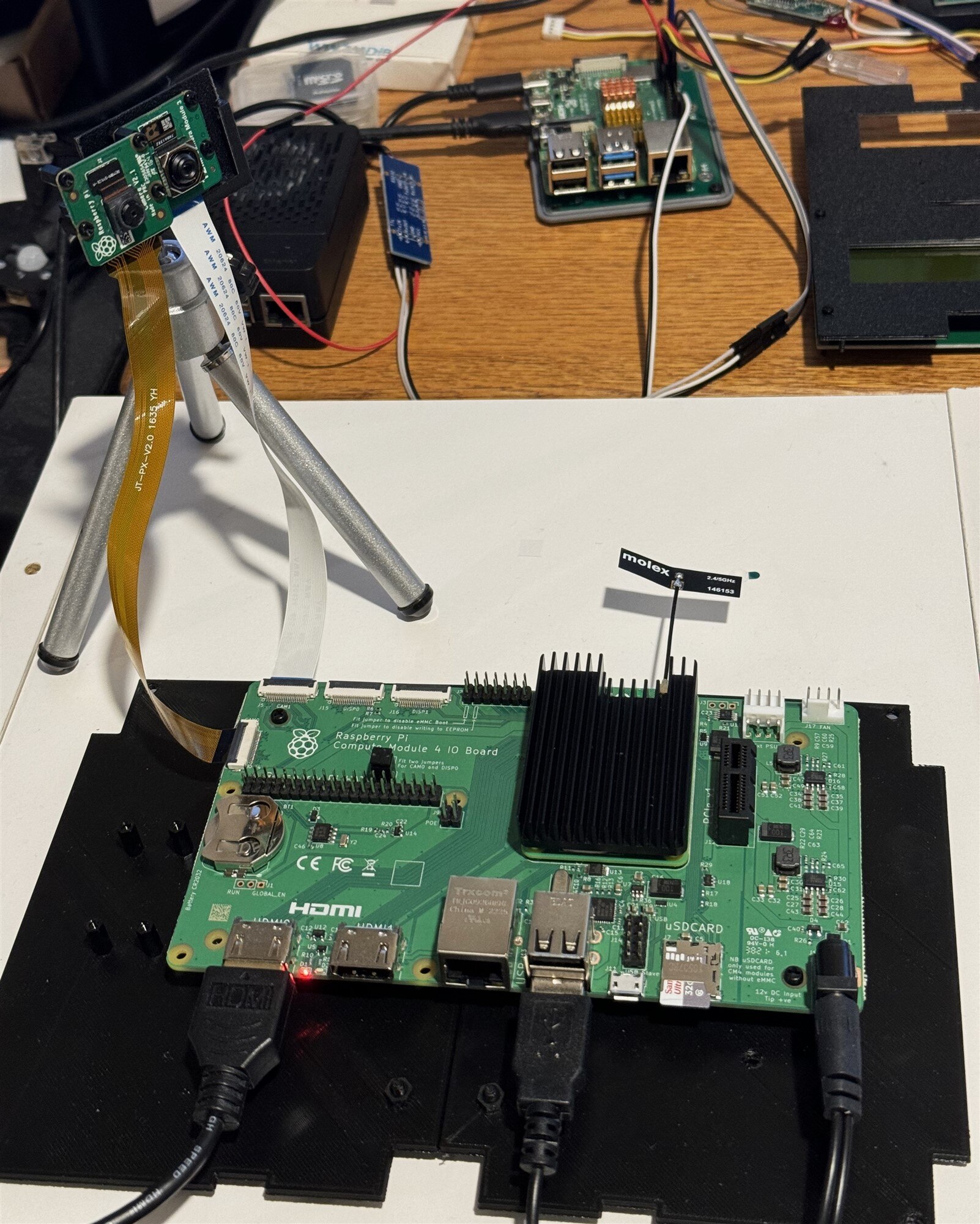
I initially started software development on an RPi4 with 8GB of memory. I have started the transition to the CM4 + CM4 IO board assembly. This will initially be powered with a +12V power adapter and will transition to being powered by the charge controller when the enclosure is moved outdoors.
Here is a view of my current setup. I have the CM4 mounted on the CM4 IO board. The WiFi antenna and heatsink are attached. You can see the RPi4 that I was using for initial development in the background. I have added a CR2032 battery for the RTC and am currently playing with a dual camera setup. A V2.1 is on the left and a V3 is on the right. I will only use the V3 in the final project.
So far, moving from the RPi4 to the CM4 setup has been fairly straightforward. No issues with the software, just moved the SD card over. I did have to change the cable on the V3 camera because the CM4 IO board uses a 22p 0.5mm pitch CSI connector like the RPi Zero instead of the 15p 1.0mm pitch connector on the RPi4. Adding new features like the RTC and second camera did require adding device tree overlays to /boot/firmware/config.txt.
Dual Camera Operation
Here is a comparison of the two cameras running object detection in artifical light (2700K). The V3 has wider FOV, autofocus, and better color rendering.
The two cameras running "simultaneously" - just individual rpicam-hello preview windows running from separate terminal processes. The performance should improve a lot when I figure out how to run multiple threads. It's hard to read the banner on the window, but both windows are running 30fps most of the time. One of the windows will sometimes drop to 15 fps and you can also see an occasional tear in the video. This is with natural daylight through a skylight. The windows are sized at 960x720. Performance is more consistent at 30 fps with windows 640x480 and smaller.
RTC
The RTC and the second camera required the following additions to the config.txt:
dtoverlay=imx219,cam0
dtoverlay=i2c-rtc,pcf85063a,i2c_csi_dsi
The imx219 is the sensor used on the V2 camera.
The RTC overlay was a bit harder to figure out. It would have been nice if the CM4 IO manual would have just specified what was required. There are quite a few I2C buses on the CM4 and muxing of peripherals onto those buses so the specific overlay syntax is dependent on the PCB implementation. In this case the RTC used on the CM4 IO is a pcf85063a and it is sharing an I2C bus with the second (cam0) camera.
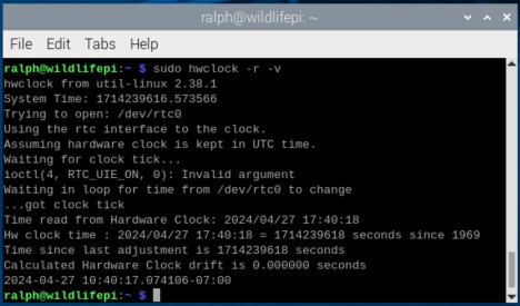
The other gotcha is that the Linux hwclock command requires root permission. If you don't use sudo it doesn't complain, just doesn't work.
Here is a verbose response to a query. Interesting that I didn't have to specify that I wanted local time.
Front Panel Assembly
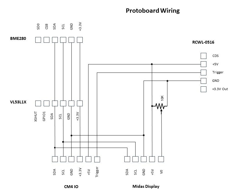
The front panel holds the sensors (BME280, VL53L1X, and RCWL-0516), the RPi Camera Module 3, and the Midas Display. The sensors will be mounted on a protoboard that aggregates the I2C bus and +3.3V (BME280, VL53L1X) and +5V (RCWL-0516, Display) power.
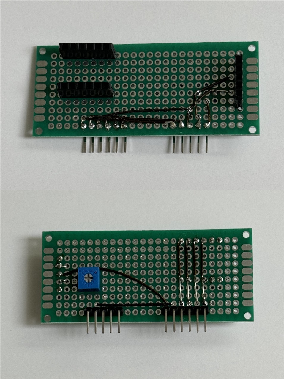
I find it easier to use a physical layout rather than a schematic when wiring and debugging a protoboard. I have socket headers for the sensors and right angle pin headers for the cable down to the CM4 IO and across to the Midas Display. I also added a potentiometer for the display contrast adjustment.
The completed protoboard. Not my best work. I was struggling to solder the wires and I realized that my trusty 30+ year old Weller WTCPN soldering station appears to be having problems maintaining temperature. And unfortunately in an earlier attempt at cleaning and organization I have managed to misplace my spare soldering station and spare Weller tips. Never grow old as my mother used to say...
Anyway, I managed to finish and the connections buzz out okay.
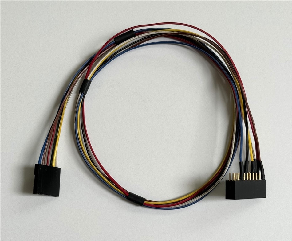
Then I made a wire harness to connect the Protoboard to the CM4 IO GPIO connector. I used a 1x6 socket connector with crimped pins on the protoboard end and a 2x10 socket connector with soldered connections (I didn't have one that used crimped pins) for the CM4 IO GPIO connector.
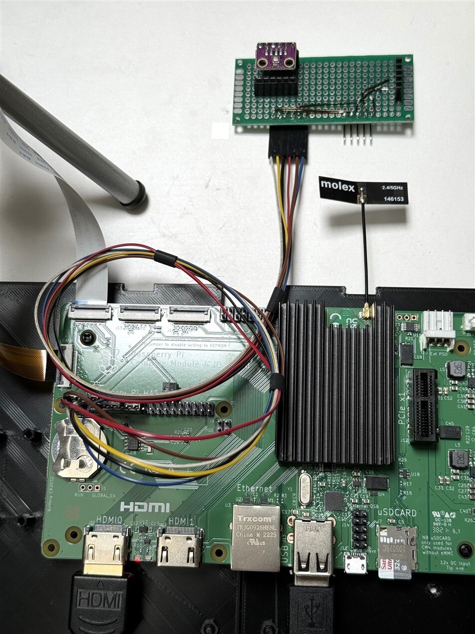
I believe in baby steps so I did a quick test of the connected boards only using the BME280 and that was successful.
Enclosure Assembly
4 pin Amphenol connector
I needed to wire the mating halves of the 4 pin connector pair. The external connector terminates the load cable from the charge controller. This cable carries the +/- load outputs (nominally the switched battery voltage and ground). I use the other 2 conductors for the TX/RX outputs of the controller RS-232 UART. I'm using a 4 conductor 16 AWG cable. Bit of an overkill for TX/RX but it fits snugly into the connector backshell gasket and makes a nice tidy assembly. The solder cups on the connector just barely fit the 16 AWG stranded wire.
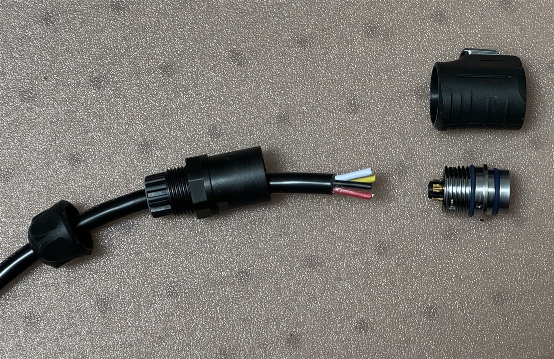
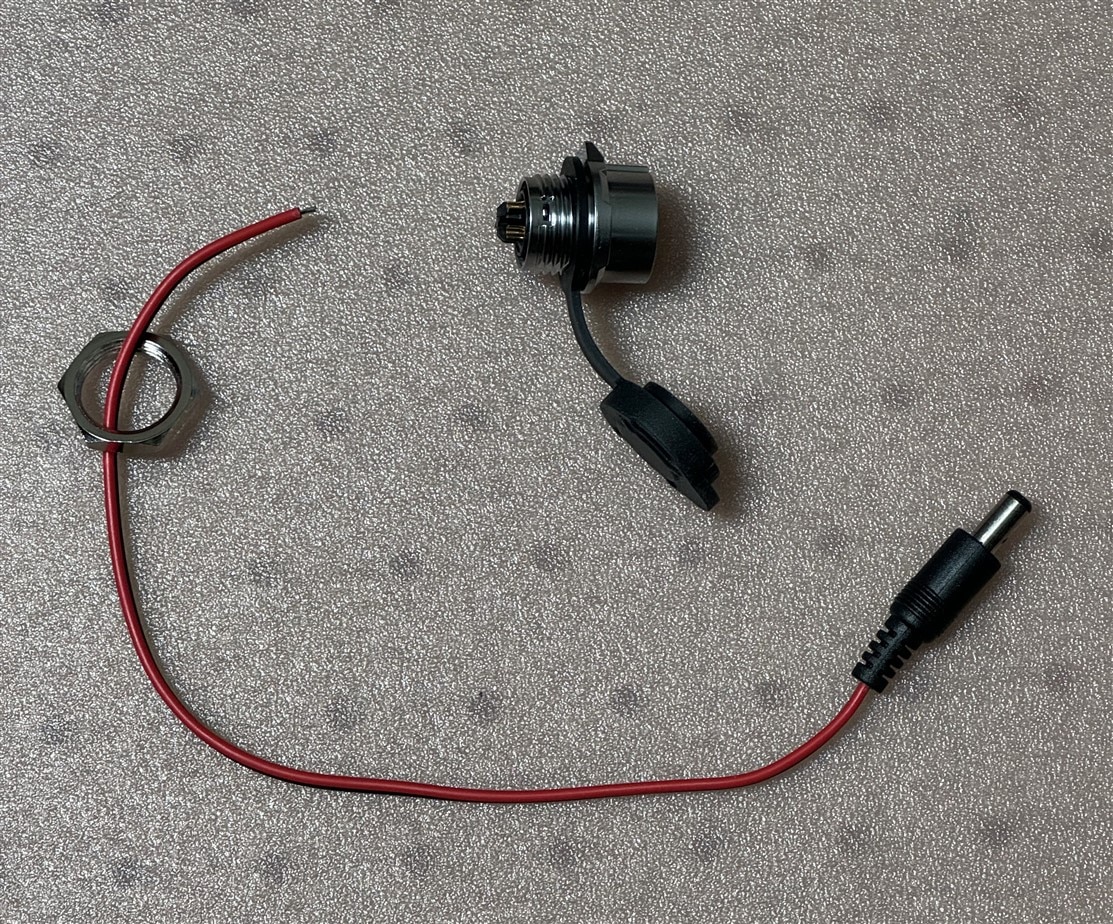
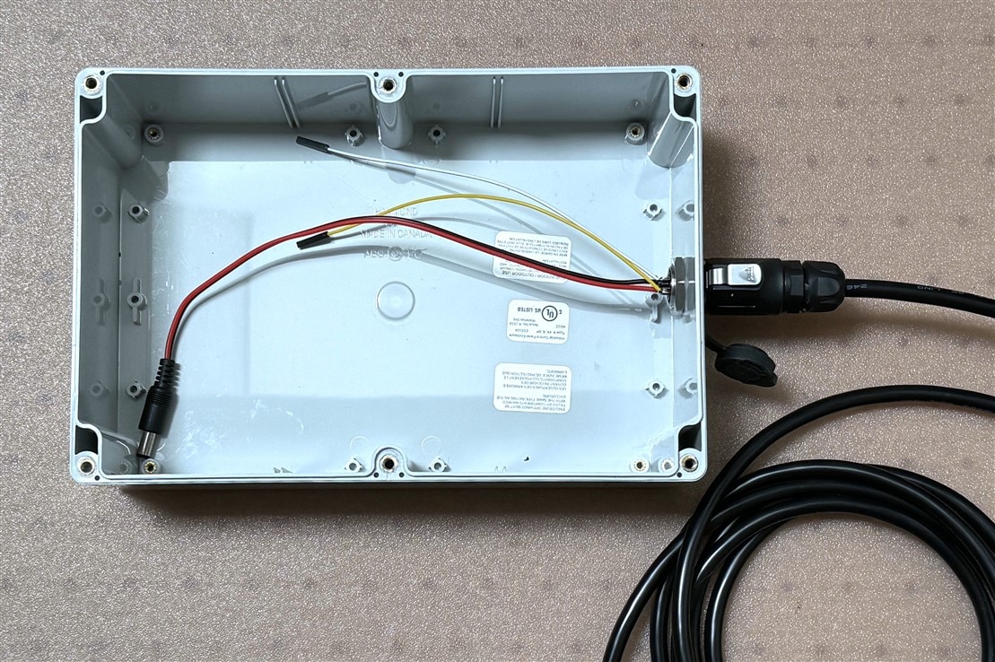
On the enclosure side the mating panel connector is wired to a barrel plug pigtail to the power jack on the CM4 IO. And the TX/RX pins are connected to a 2 pin jumper pigtail to the RS-232 to TTL level shifter mounted next to the CM4 IO.
The completed assemblies mated together.
Summary
There is still a lot of work to be done. I need to finish the rest of assembly and test and to do lots of software work and data collection and testing. I am going to wait to document the finished project until the final challenge blog post. Due to lack of free time in the next few weeks, I'm a little concerned that I will be able to complete all that I had intended by May 20. Seems like it's just around the corner...
Links to other Project Blogs
| Blog 1 - Introduction | |
| Blog 2 - Unboxing and Parts Description | |
| Blog 3 - Enclosure Modification | |
| Blog 4 - Software Development |
