Hello everyone. Last week I received my MAX25405 Evaluation Kit which we use as part of Experimenting with Gesture Sensors Design Challenge. Because It is very advanced evaluation kit I will describe my first thoughts about it in multiple blog posts. In my first blog I described my plans as part competition. In this blog post I will show the hardware part. Later I will describe software part. Currently I spend first few hours with kit and TLDR version (spoiler alert!) is that MAX5405 is very capable gesture sensor and is better than I originally expect. 60 pixels are enough for very cool features which I will show in later project.
Box
Kit come packed in white non-branded white box with multiple labels. One label come from Maxim. It is similar label which is on all Maxim EVKITs and second label come from Farnell store. Whole content of box was protected by antistatic foam. After removing first (two) layers of antistatic foam Kit contained multiple other antistatic packs containing PCBs. There were totally five antistatic packs. Three contains PCBs and remaining two contains cable and power adapter.

First PCB is the main sensor board.

Almost all passives are on back side. Board is approximately 17.6 cm long. Before receiving I expected it slightly longer, but I am not good in size estimations. You may notice that board is asymmetrical, and one side contains one LED more. It is because the one LED is connected to sensor differently. Also note that only 4 of 9 LED is placed.

This board contains MAX25405 optical gesture sensor. Let’s look at hero of this design challenge in more details.

As you can see it is optical sensor so we can partially see into it. We can see some optics, optical filters, and lens as part of package. From the top we can see some layers and at the bottom we can see very small part of die.
Next board which we received is MAX32620FTHR board. It is board with microcontroller which is programmed with algorithm for (not only) detecting gestures. It is low-power microcontroller, and it is from the same family as MAX32625 which I reviewed as part MAX31343 RTC Shield RoadTest. If you are interesting in more details about this similar microcontroller then you can read my Review of MAX32625 MCU and MAX32625PICO board blog post. Most information which I wrote as part of that review apply to MAX32620 also.

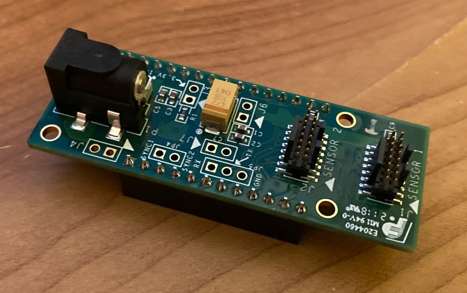
The last PCB is shield for interconnecting MAX32620FTHR microcontroller board with sensor board.

For interconnection shield and MCU board, we received 2x8 pins ribbon cable. We received approximately 15.5 cm long one:

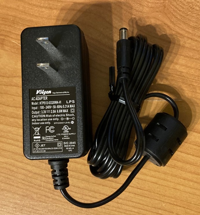
And finally, we received power adapter for converting AC voltage from outlet to DC 3.3 volts.

The only issue is that it is used for American plugs but I am located in Europe and in Europe we use different plugs.
Powering the MAX25405 Evaluation Kit without US socket
For this reason, I had to deploy alternate way of powering this kit. Note that board requires external power supply because MAX32620FTHR from its 3.3V branch cannot source required amount of current for powering IR LEDs. They are quite a hungry LEDs. Every LED is designed to handle as much as 100 mA. Murphy laws apply and I have lot of 24V, 12V and 5V adapters but no 3.3V. Because I did not find any suitable 3.3V adapter with barrel jack I decided to check shield schematics for alternative way of powering. Note that this schematic is not public, but Maxim Tech Support kindly send it me without need to sign any NDA. I found that power jack supply is directly connected to JP3. So, I soldered JP3 jumper pinhead. It is red pinhead on following image and was not on previous image in unboxing section.

For making 3.3V I used myself designed DC/DC module with MAX16935 Step down regulator (I also chosen it because it contains Maxim’s DC/DC Step-Down Regulator and Maxim sponsored this contest). It is the same regulator which I use when Experimenting with MAX40080 as part of previous contest and the same module I used and shown in my Project14 Digitally Adjustable Power Supply project. This module I used from converting 12V from power adapter to 3.3V on pinheads:

After connecting and powering it looked like this:

And in this setup my sensor worked.
Closing
Thank you reading this blog. In this blog I shown my first steps with MAX25405 Kit from Hardware side of view. In next blog post I will show “unboxing” from software side of view. I will show program with GUI which Maxim offers for evaluating this the kit and allows us to use MAX2405 without any programming need. It is nice tool for first evaluation on sensor performance.
Thank you again for reading this blog post and stay tuned to next parts. If you have any question or feedback, feel free to comment below.
Next blog: Blog #3: Experimenting with MAX25405 EVKIT GUI Program


-

DAB
-
Cancel
-
Vote Up
0
Vote Down
-
-
Sign in to reply
-
More
-
Cancel
Comment-

DAB
-
Cancel
-
Vote Up
0
Vote Down
-
-
Sign in to reply
-
More
-
Cancel
Children