


Table of Contents
Introduction
As explained in my introductory blog, my design challenge is to evaluate whether I can get the MAX25405 gesture sensor platform to behave as a touch free gesture mouse, which can plug into a computer or TV USB port.
In my first experiment blog, I confirmed that I could get the MAX32620FTHR to behave as a USB mouser using the MbedOS USBmouse API. So that was a good start.
For this, my second experiment, I now wanted to evaluate how well the gesture sensor reacts to my own gestures using the Windows only GUI demo software provided by Maxim Integrated. This desktop PC software only works with the firmware that comes embedded on the MAX3260FTHR board. So all experiments shown are based on this embedded firmware. To undertake this experiment, I set up some goals:
- My first goal was to determine whether the sensor would perform well in the 10cm to 20cm range, which is the distance I estimated as the most likely for hand gestures when sitting down in front of a computer.
- My second goal was to evaluate whether your body would interfere with the results if you are sitting about 40cm away.
- Finally, my third goal was to determine how easy it is to replicate different gestures and what methods work better than others versus which methods are problematic.
In all cases I was pleasantly surprised by the results.
Let me now explain the process.
Windows PC GUI Software
A Windows 7/10 installation package is available on the MaximIntegrated website for download. Clicking on this downloaded executable file will install the GUI software and the serial port drivers for you in a predefined directory or a folder of your choice.

When opened, the software Graphic User Interface (GUI) provides three output modes, namely: Heat Map, Gesture and Proximity. To connect with the MAX32620FTHR board, you click on the bottom right (shown in red) or use the menu toolbar and click on Device to reconnect.
For purposes of my second experiment, I only focused on the Gesture mode option.
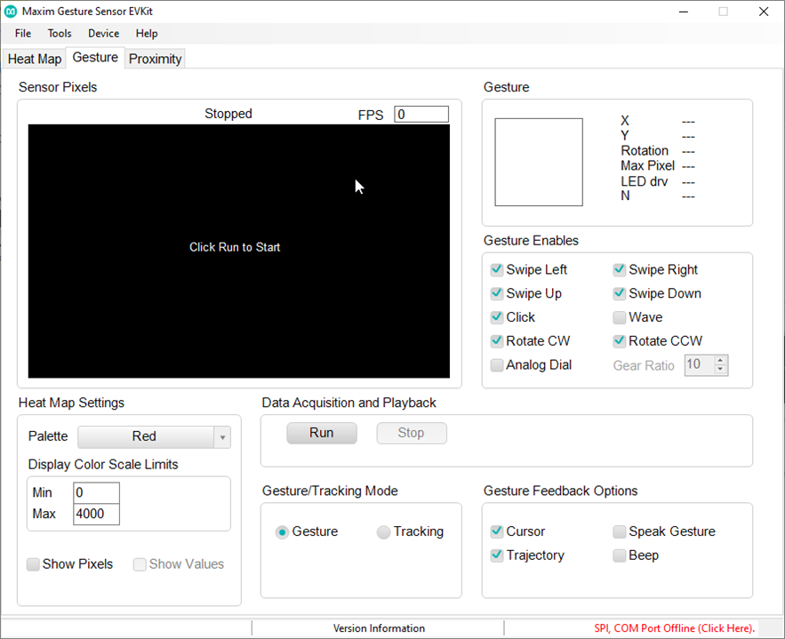
In this mode, the software interprets your gestures and responds based on what it recognises. So if you move your hand from left to right across the sensor’s field of view, it will respond with a “Swipe Left” icon etc. If it does not recognise the movement, it will show an X in the gesture icon box (shown top right).
After having played with the sensor and the software a bit, it quickly became apparent that I would get more value from the Sensor Pixels map output, than whether the enabled Gestures (as shown on the right) were being detected, or otherwise, with my hand gesturing. Hopefully this is demonstrated in my test videos (see below).
Test Apparatus

(image source: Maxim ir-gesture-recognition-for-auto-displays-solution-guide.pdf)
The max25405 sensor board includes the necessary infrared LED’s and the sensor itself. The PCB itself is connected via a ribbon cable to a “feather” shield, which includes a separate power source for the LED’s. The shield is then connected to the MAX32620FTHR using the header connectors. The sensor evaluation kit does not include a stand for the printed circuit board (PCB).
As such, I had to come up with a suitable test apparatus that would suit the sensor parameters (as shown below), in particular the field-of-view (FOV) angle for the MAX25405 sensor.
(table source: Maxim ir-gesture-recognition-for-auto-displays-solution-guide.pdf)

From this table we can see that the FOV for the MAX25405 is 30 degrees, which means that if you gesture at a distance of 40cm away from the sensor, the sensor detection radius is about 22cm.
However, the sensor itself is not square but is actually rectangular, which is made up of a matrix of 6 by 10 IR detectors, as illustrated below. So the height range is slightly less than the width of the FOV. It’s interesting to note that there is a good degree of overlap of the FOV of each detector cell in the matrix. Hence, the detection algorithm in determining the gesture movement will become quite important in correctly determining one gesture from the next. Anyway, worrying about algorithms comes later in the project.

For now, I just need a suitable test apparatus.
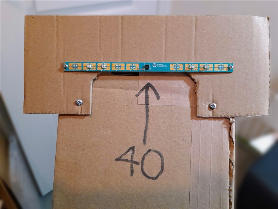
Well, I for one am a great believer in recycling, and as my apparatus will be temporary and likely to change, the best material to use is in fact cardboard. The important criteria in this case is height. So I used a long 40cm long box, as shown below, with a cardboard cutout attached on top.
| {gallery:autoplay=false}Test Apparatus |
|---|
|
|
|
|

Please note that you’ll probably get a better view of the test apparatus in the videos.
Gesture Tests
My test procedure was based on free-form experimentation so as to get a feel for how the sensor detects movement. The results from these experiments are of course heavily biased on the configuration parameters used in the demo software, which are not available for review - so I’ll have to figure that out later.
Still, I was very happy with what I observed and this gives me sufficient confidence that a gesture mouse is still very much achievable, even if it turns out to be rather rudimentary.
Here are two videos capturing some of my tests, which helped answer my questions. Please note that two video captures were taking place so some timings may be slightly off. In the second video, I actually used playback where data is first logged in a file and then afterwards you can open and play back the results. In this case I did notice variations in timings due to different rates etc.
Video 1: Test of basic gesture movement at different distances
Here I was able to answer my first two test goals.
Yes, the sensor definitely worked well in the 10cm to 20cm range and the distances for different gestures to work reliably seemed to tally with those given in Table 1 (Gesture Selection Guide), as shown in the previous section. I did notice that at 40cm, you had to use the palm of your hand for basic movement to be detected. The good news for my application was that my body seldom interfered with the results and I foresee that this will be something that could readily be filtered out.
I also noticed that there were some timing delays between each gesture being correctly detected. For example, if you moved your hand from left to right and then went back (right to left) with delay it would very seldom detect the right to left gesture. You had to pause a moment for the second to be reliably detected.
I also noticed that vertical gestures were less consistently detected compared to horizontal gestures.
The big surprise for me was how well finger gestures worked compared to hand gesturing. At short distances (approx. 15cm) I could simply use my index finger and I achieved very good resolution and gesture detection. Using figure gestures for rotational gestures (CW/CCW) was very reliable.
Video 2: Test of random gesture movements together with data logging
In this test I tried random gestures to see how well the pattern would replicate on the pixel map. Here I discovered that diagonal movements worked pretty well. I was also able to capture a “U” and a “∩” too, although this needs more practice.
The data captured from the GUI software is intriguing as it provides individual pixel values for all 60 cells in the 6x10 matrix, frame by frame in a CSV file. You determine how many frames to capture, so it can be quite a lot of data. I will have yet to work out whether analysing this data in detail will help or hinder.

Next steps
As I have now discovered that the firmware provided is somewhat outdated and requires significant change, I am now planning on working on the code as well as trying to make sense of the configuration parameters to obtain valid gesture movements.
In the meantime, there is no harm coming up with other experiments along the way to help rule in / rule out options.
Fingers crossed we get there.
Addendum: Testing air clicks and flicks
While my core tests provided sufficient evidence that I could create a range of gestures, using gesture mode, which would be suitable for my gesture mouse project, I had not documented my tests for mouse clicks.

As such here is a short video showing a possible option for left and right button mouse clicks using Windows GUI software proximity mode. I also tested air flicks using the proximity mode.
While the test results seem reasonable, I must admit it just didn’t feel right doing air clicks (i.e. pushing palm of hand towards sensor). Mind you I was standing at the time and this action did not feel natural from where I was standing compared to doing gestures.
Now that I am sitting down typing this addendum and replicating the hand movement, it does feel better although I think air flicks might work better as mouse clicks. We will see as I suspect it will depend on where the sensor is placed.
Top Comments