In the previous blogs I have mentioned about the project I am doing for Experimenting with Industrial Automation in detail and getting started with the kit. Now in this blog I will mention the technical details of the project. This Blog mainly has two parts such as hardware installation of the devices and wiring and software development such as logic and other project related settings.
This is Blog 4 in five part Blog series.
-
Overhead tank monitoring for smart home/industry : BLOG 1
-
Overhead tank monitoring for smart home/industry : BLOG 2
-
Overhead tank monitoring for smart home/industry : BLOG 3
Table of Contents
- Overhead tank monitoring for smart home/industry : BLOG 1
- Overhead tank monitoring for smart home/industry : BLOG 2
- Overhead tank monitoring for smart home/industry : BLOG 3
- Safety information
- HMI and PLC communication
- Harmony Hub ZBRN2 and PLC communication
- Harmony Hub ZBRN2 and wireless receiver ZBRRH communication
- Controlling the relay
- ZBRA1 Antenna
- Sensor and PLC communication
- Reference Documentation
Safety information
Before starting to work with Schneider Electric devices it is required to note some safety related information. It is advice for uses to read the instructions carefully. Failure to do so can result in equipment damage, electric shocks or even death. So here I will deliberately post some dangers and warnings as mentioned in the user guide of Harmony hub(ZBRN2). It would be enough to read but one should consult respective devices' user guide for warnings and dangers that needs to be considered.
HMI and PLC communication
In order to have correct sensor data there needs to be a communication between HMI module and PLC itself. There are some methods to do that. One of them is using the nodename of the PLC and other is by using the IP address of the device. I will post more on this in my final blog post.
Harmony Hub ZBRN2 and PLC communication
Harmony Hub supports Modbus communication. ZBRN2 has only serial port to communicate to the PLC. Modbus protocol uses some registers to access data. Such as read/write bit values or register(byte) values. To my understanding it is similar to I2C and SPI protocols that I have used in the past. So the Harmony Hub registers can be accessed using Modbus RTU/ASCII protocol supported in EcoStructure Machine expert over serial connection to the PLC.
Following images shows the device on the EcoStructure project Device tree and Modbus channel configurations.
| {gallery}My Gallery Title |
|---|
|
EcoStructure Modbus device registers |
|
Adding ZBRN2 Harmony hub on serial port |
|
Modbus device channels |
|
|
Harmony Hub ZBRN2 and wireless receiver ZBRRH communication
ZBRRH is the wireless receiver module capable of receiving commands from the PLC through Harmony hub. How is that actually possible?
Harmony hub has input and output channels that can receive commands from push buttons as state of inputs and ZBRRH wireless receivers that can act as state of output channels on Harmony Hub. Using the jog-dial on the ZBRN2 one can associate output channels on the hub to the wireless receivers. As I showed in blog-3 already, push buttons can be associated with input channels on the Harmony hub. Similarly, in this blog I will mention how output channels can be associated with ZBRRH receivers.
One thing to mention here is that upto 60 ZBRRH receivers can be associated with Harmony Hub. Meaning that one can control so many devices(at least 60!) directly. But using some techniques in digital electronics one can control 60x4=240 discreet devices.
Following illustration from the user guide of Harmony Hub shows how to control different outputs of the receiver module. Once assigned output channel, Modbus request could be sent to the output registers of the Harmony Hub.
Before working with Modbus output registers following care must be taken(as per the user guide).
Controlling the relay
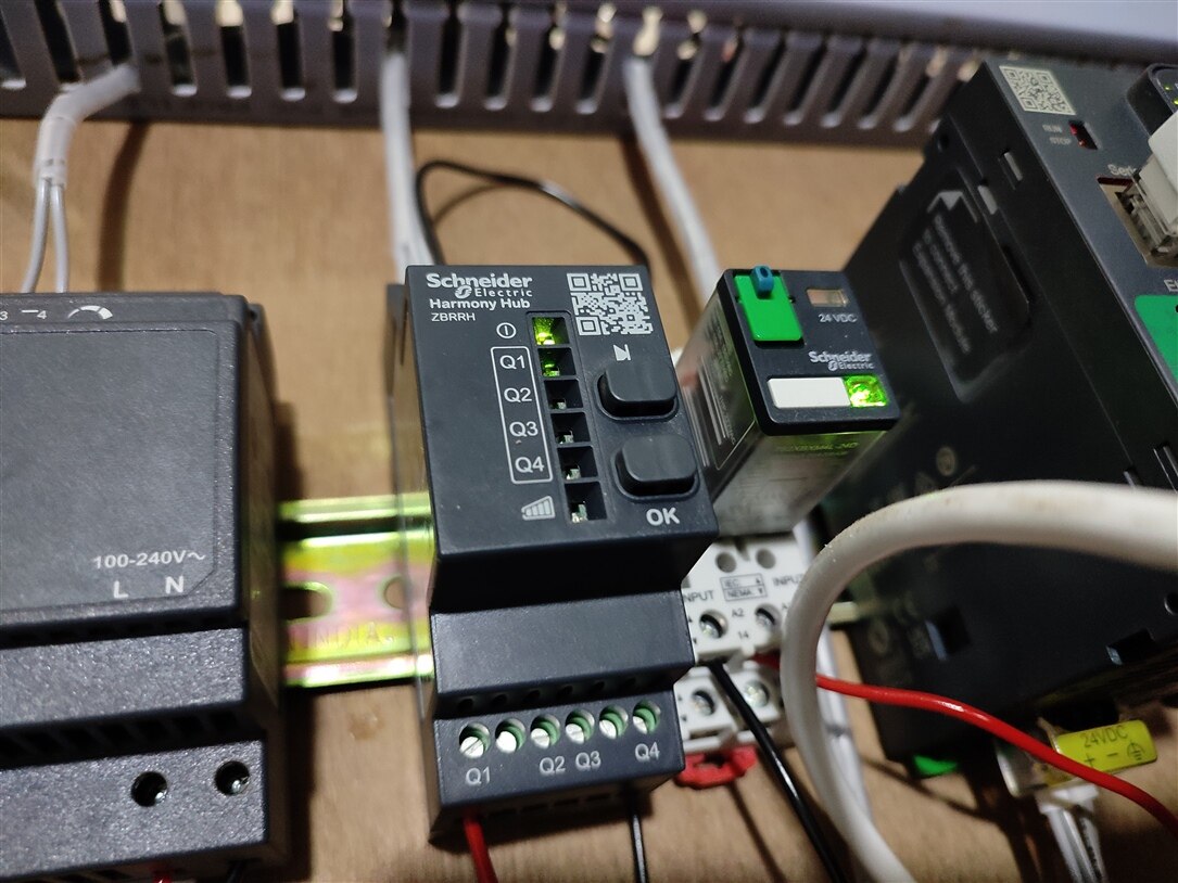
The 24V relay(782XBXM4L-24D) can be controlled remotely from PLC using Harmony hub receiver module(ZBRRH). This relay can eventually turn on/off the motor to control the water flow in the respective tank. It is possible to control upto 4 relay modules given that power supply can provide enough power to control these relay coils. The following image shows Q1 output of ZBRRH is turned on that is connected to the relay module.
The question here would be how one can turn ON/OFF respective outputs(Q1.....Q4)? These outputs can be turned ON/OFF by writing to respective Modbus registers.
The following values are possible as per the user's guide
- 0x00 -- Output off
- 0x5A -- Output blink
- 0xFF -- Output on

ZBRA1 Antenna
ZBRA1 is the antenna that can be used to increase the signal transmission range. The antenna is capable of handling varied voltage range from 24....240 vDC/AC. It comes with 5 meters of cable wire and can be easily mounted on to surface. Harmony Hub(ZBRN2) has association process to link the antenna to the RF channel.
Sensor and PLC communication
I will write about it in the final blog post.
Reference Documentation
Harmony Hub ZBRN2 user guide
ZBRA1 Antenna user guide

