I'm still learning more about image processing before I start building my Experimenting with Sensor Fusion Challenge project. In this blog I share my experiences rebuilding the Xilinx MIPI CSI-2 RX subsystem IP Core sample application. The application is a CSI-2 based image processing system that outputs images through DSI or HDMI outputs.
Here the end result. In less than 30 minutes of work I have the solution built and working. The response of the solution is impressive despite being a low-end HDMI monitor.

The Xilinx SP701 Evaluation Kit provides mechanisms to interface with high-performance cameras and display systems using the Mobile Industry Processor Interface (MIPI) Camera Specification Interface 2 (CSI-2) and Display Specification Interface (DSI).
Both interfaces are connected to a Spartan-7 FPGA which is capable of directly interfacing with the CSI-2 and DSI.
A short video of the final solution. The lighting is very bad just behind my head is the ceiling lamp so there is a second lamp in front to be able to illuminate my face a bit. At the end of the blog there are similar tests but capturing the image with an HDMI video grabber for PC instead of viewing the image on the portable HDMI monitor.
Table of Contents
- Hardware
- Digilent Pcam 5C
- Introduction to imaging solutions
- About the Mobile Industry Processor Interface (MIPI)
- About Image Sensor Processors (ISP)
- Building the Application Example Design
- Dissecting the example application module by module
- Building the Microblaze App
- Setup the system
- Using a USB Video Capture Dongle
- Block design in pdf
- Related documents and links
- Conclusions
- Next Steps
- The Complete "Sensor Fusion for Firefighters" Blog Series
The Complete "Sensor Fusion for Firefighters" Blog Series
- Sensor Fusion for Firefighters. Introductory blog
- Sensor Fusion for Firefighters. Getting Started with the AMD Xilinx SP701
- Sensor Fusion for Firefighters. AMD Xilinx SP701 - MIPI Video Pipe Camera to HDMI Display
- Sensor Fusion for Firefighters. Displaying heads-up video on the live feed
- Sensor Fusion for Firefighters. Environmental monitor heads-up display on Xilinx Spartan-7 SP701 development board
- Sensor Fusion for Firefighters. Compass and Environmental HUD monitor with the Spartan-7
- Sensor Fusion for Firefighters. Thermal Vision, Compass and Environmental HUD monitor with the Spartan-7
- Sensor Fusion for Firefighters. Summary Blog
Hardware
To build the system you need:
- ;AMD Xilinx SP701 evaluation board and power supply
- JTAG USB Platform cable or USB cable Type A to micro - B
- HDMI cable
- HDMI Monitor: ELECROW 7" HDMI IPS Monitor - 1024x600
- Digilent Pcam 5C sensor module
- Host PC (to program and communicate with the program via UART)
Digilent Pcam 5C
The sample application uses the Digilent Pcam 5C . The Pcam 5C is an imaging module meant for use with FPGA development boards. The module is designed around the Omnivision OV5640 5-megapixel (MP) color image sensor. The Pcam 5C comes with a 10 cm flat-flexible cable and a factory-installed fixed focus lens with M12 lens mount, so it is ready to use out of the box.
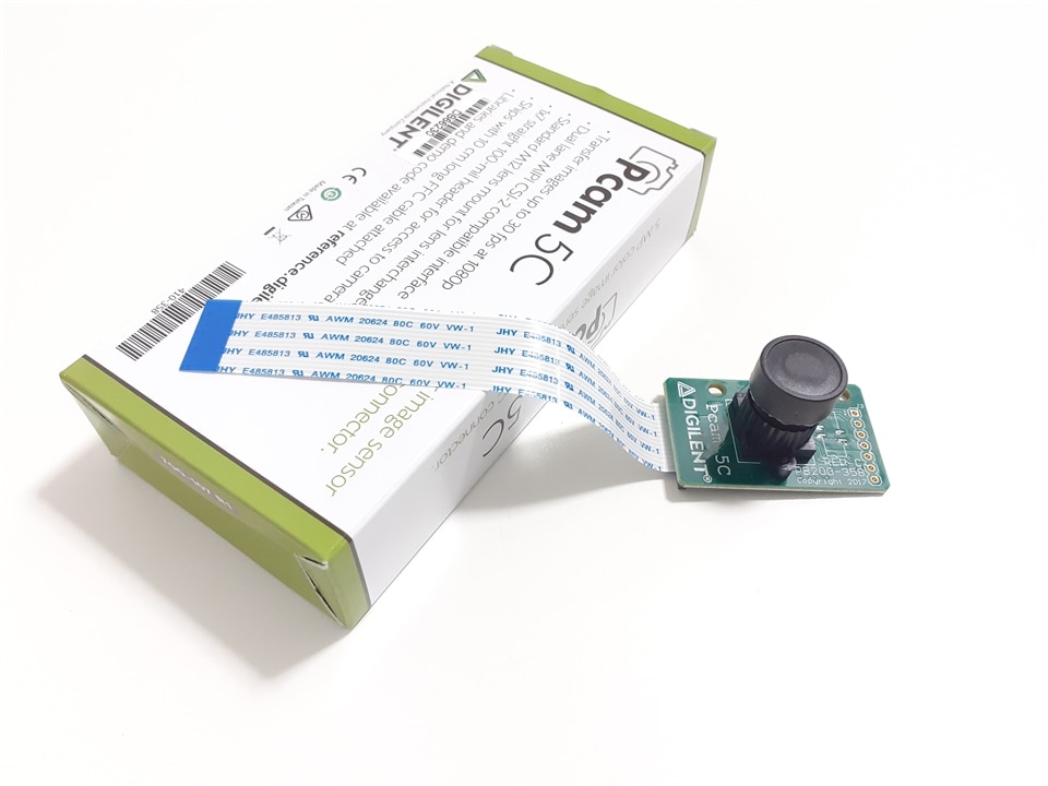
This sensor includes various internal processing functions that can improve image quality, including automatic white balance, automatic black level calibration, and controls for adjusting saturation, hue, gamma and sharpness.
Data is transferred over a dual-lane MIPI CSI-2 interface, which provides enough data bandwidth to support common video streaming formats such as 1080p (at 30 frames per second) and 720p (at 60 frames per second).
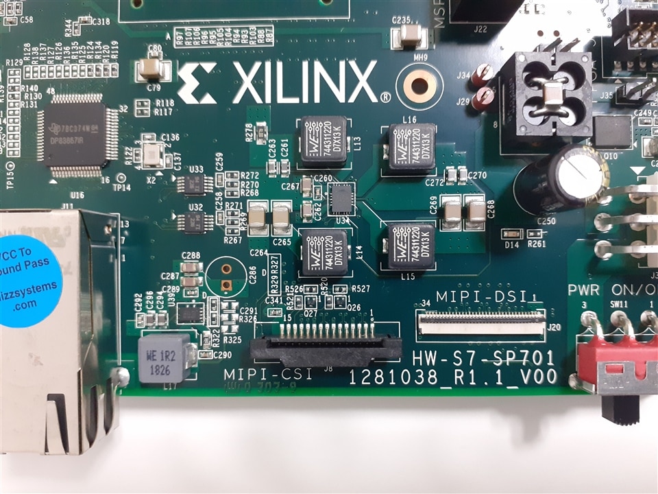
The module is connected to the MPI-CSI connector of the SP701 FPGA development board via a 15-pin flat-flexible cable (FFC) that is pin compatible with the connector found on the popular Raspberry Pi development board.
Each MIPI DPHY link may have between one and four high-speed serial links operating at up to 2.5 Gbps or 10 Gbps across all four lanes.
Data transfer over these lanes occurs at double the data rate and is synchronous to the clock lane.
Omnivision OV5640 5-megapixel (MP) color image sensor. See related links for specs.
Introduction to imaging solutions
Before going into detail with the example, I needed to learn about the video and image processing solutions offered by the development kit and some general knowledge about this technology that I did not know.
About the Mobile Industry Processor Interface (MIPI)
MIPI is a high-bandwidth, point-to-point protocol used to transfer image sensor or display information over several differential serial lanes.
It works on the OSI model with different layers of implementation.
The lowest level of the MIPI protocol is the DPHY, which defines the number of lanes, clocking, and the rather unique transition between differential (Scalable Low Voltage Swing - SLVS) and single-ended signaling (LVCMOS).
This combination of high-speed differential and low-speed, single-ended signaling enables the high-bandwidth transfer of the image/display data using a higher-level protocol such as CSI-2 or DSI. The low-speed communication enables the low-level protocol information to be communicated at lower power.
Xilinx MIPI cores
Xilinx provides several useful MIPI cores as
- CSI-2 Receiver and Transmitter Controller Subsystems
- and DSI Transmitter Controller Subsystem

ADV7511 - 225 MHz High-Definition Multimedia Interface (HDMI) transmitter
In addition to the Spartan-7 FPGA on the SP701, the board also have an HDMI - ADV7511 supporting HDMI 1.4 and MIPI CSI and DSI interfaces.

The ADV7511 is a 225 MHz High-Definition Multimedia Interface (HDMI) transmitter. The digital video interface contains an HDMI 1.4- and a DVI 1.0- compatible transmitter and supports all HDTV formats (including 1080p with 12-bit Deep Color). The ADV7511 supports the HDMI 1.4-specific features, HEAC (ARC), and 3D video. In addition to these features, the ADV7511 supports x.v.Color, high bit rate audio, and programmable AVI InfoFrames. The ADV7511 supports both S/PDIF and 8-channel I2 S audio.
About Image Sensor Processors (ISP)
Images captured by a CMOS/CCD image sensor are monochrome in nature. To generate a color image, three primary colors (typically red, green, and blue) are required for each pixel. Before the invention of color image sensors, the color image was created by superimposing three identical images with three different primary colors. These images were captured by placing different color filters in front of the sensor, allowing a certain bandwidth of the visible light to pass through.
Modern sensors capture images with only one color/pixel called Raw or Bayer Images. To reconstruct the image, Image Sensor Processors (ISP) interpolate the values of the three primary colors (RGB) for each pixel using a Debayer function.
Debayer is also called Demosaic and is the minimum function required of an ISP. Additional ISP image enhancement functions include: noise reduction, stuck pixel correction, 3A algorithm to adjust for light conditions, gamma and color correction.
The Bayer arrangement of color filters on the pixel array of an image sensor. Each two-by-two cell contains two green, one blue, and one red filter (Wikipedia)
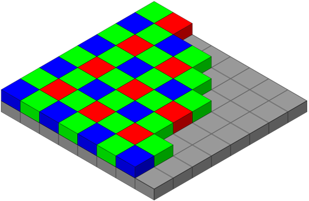
ISPs transform raw Image sensor output to a usable picture. All ISPs have tradeoffs according to application: Mobile phone ISPs are designed to enhance human attractiveness in selfies, traditional DSRL ISPs are optimized to produce images for a variety of subjects, automotive ISPs are designed to deal with difficult lighting conditions and PC and tablet ISPs are designed for video conferencing.
Using an ISP intended for another application further degrades performance. ISPs manipulate image data to produce images that appear more suitable for the task: color manipulations, local & global tone mapping, skin smoothing, sky enhancements, etc...
Xilinx Demosaic IP Core
Xilinx includes a Demosaic (Debayer), Color Correction and Gamma LUT useful for reconstructing raw images to RGB or YUV images (PG286 and PG285). It does not include advanced functions such 3A Algorithm or noise reduction. It comes with both Linux and Bare metal drivers.
3A Algorithm
- Auto Exposure (AE): According to the detected luminance conditions, diaphragm (lens iris), gain level, and shutter speed are controlled to keep the brightness of the image constant. Various types of exposure metering schemes are corresponded.
- Auto White Balance (AWB): Human eyes are color flexible and sense the original colors even when the illuminating light source changes. To acquire natural images, cameras need to have a similar function to human eyes, in other words, the function to correct the color depending on illuminating conditions. This is a so-called “White Balance” function.
- Auto Focus (AF): Contrast detection method that defines the focus position for the maximum contrast as the full focus. Eliminating signal noises as much as possible, auto focus function is effective even for difficult scenes, such as the one under low illumination, telescopic zooming, and others.
source: see related links
Building the Application Example Design
The MIPI CSI-2 RX Subsystem application example design from the MIPI CSI-2 RX Subsystem is provided by Xilinx with the IP core and you can rebuild i by using the Vivado flow.
Hardware details of the Application Example Design
|
Topology |
Hardware |
Processor |
Lanes, Line-rate, and Data Type |
|
MIPI Video Pipe Camera to Display |
• SP701 Rev 1.1 • PCAM-5C camera sensor module • HDMI Monitor |
MicroBlaze |
2 Lanes, |
The Application Example Design demonstrates the usage of the MIPI CSI-2 RX Subsystem and MIPI DSI TX Subsystem on Spartan -7 SP701 board.
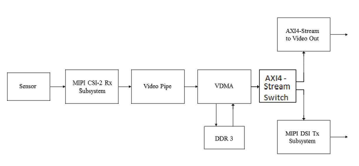
On the capture path, the system receives images captured by the Pcam-5C image sensor. Processed images are displayed on either the HDMI monitor or MIPI DSI Display.
To get started with creating this example, we first need to create a new project targeting the SP701 board.
- From the IP library, add in the MIPI CSI-2 RX subsystem.
- Once this is added into the project, double click on the MIPI IP core under the design sources. This will enable it to be reconfigured.
- Leave the configuration as it is with its default configuration and then select the application example design.
- After several minutes the design is ready.
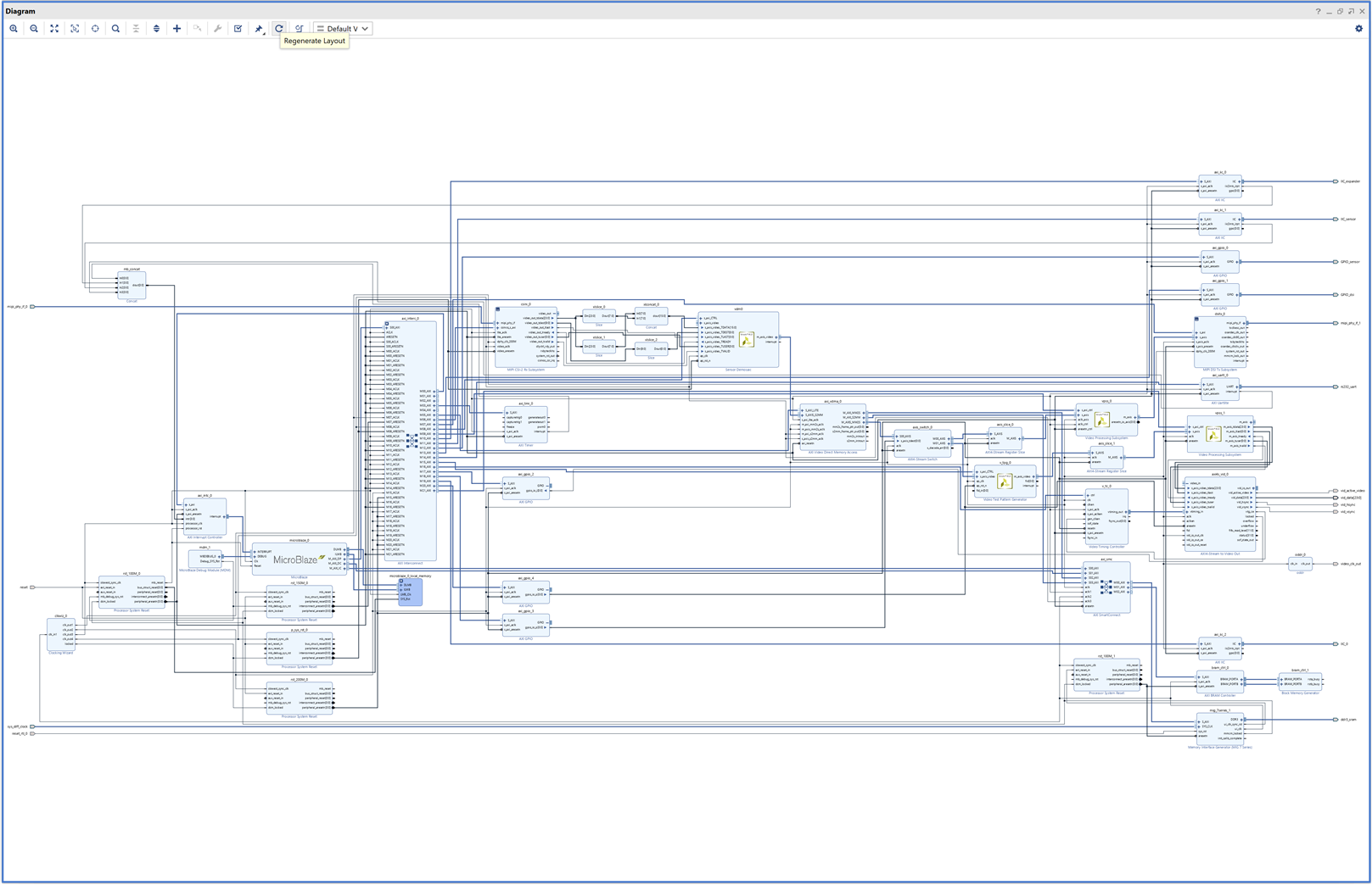
Design runs statistics. It takes about 17 minutes to build the solution.
| Elapsed Time | Run Strategy |
| 00:01:02 | Vivado Synthesis Defaults (Vivado Synthesis 2021) |
| 00:15:48 |
Vivado Implementation Defaults (Vivado Implementation 2021) |
Here is the power summary:

And the resources utilization after post-implementation. There are not many resources available, I will have to be imaginative with the solutions to generate for my application.
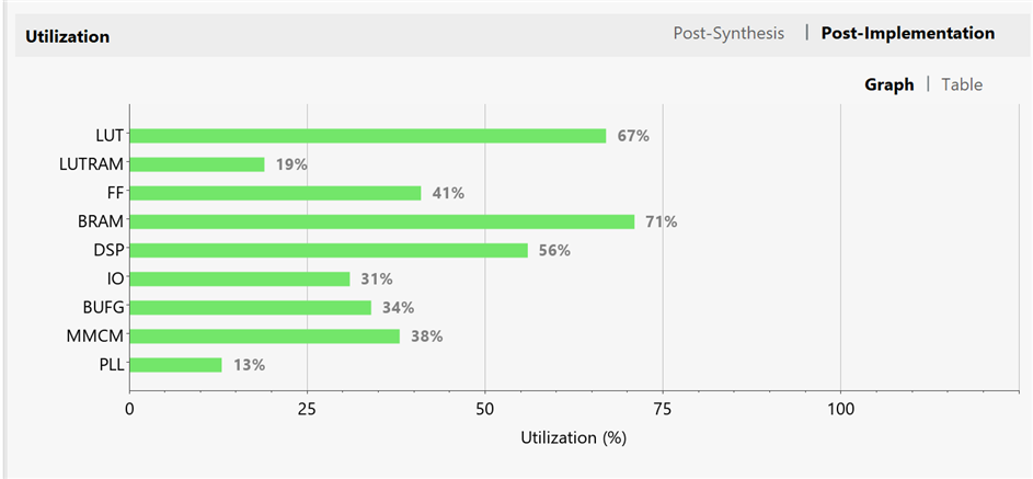
Dissecting the example application module by module
The MIPI D-PHY Controller is designed for transmission and reception of video or pixel data for camera and display interfaces. The core is used as the physical layer for higher level protocols such as the Mobile Industry Processor Interface (MIPI) Camera Serial Interface (CSI-2) and Display Serial Interface (DSI)
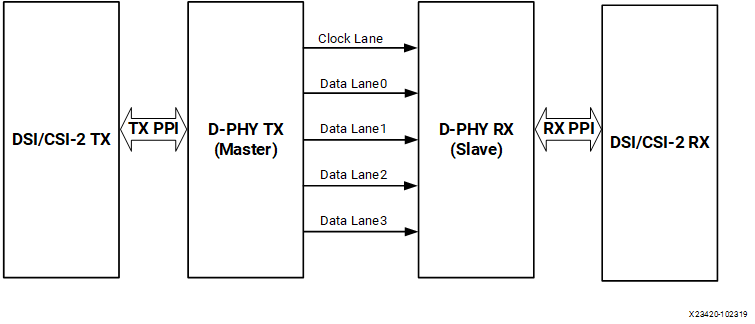
The MIPI CSI-2 RX Subsystem decodes, processes video data and presents on AXI4-Stream data with two pixels data per clock.

The subsystem consists of the following sub-cores:
- MIPI D-PHY
- MIPI CSI-2 RX Controller
- AXI Crossbar/Smart Connect
- Video Format Bridge
The MIPI D-PHY IP core implements a D-PHY RX interface and provides PHY protocol layer support compatible with the CSI-2 RX interface. For the 7 series devices the clock capable I/O should be selected manually. In addition, the 7 series devices do not have a native MIPI IOB support. You will have to target either HR bank I/O or HP bank I/O for the MIPI IP implementation.
The MIPI CSI-2 RX Controller core consists of multiple layers defined in the MIPI CSI-2 RX, such as the lane management layer, low level protocol and byte to pixel conversion.
The MIPI CSI-2 RX Controller core receives 8-bit data per lane, with support for up to 4 lanes, from the MIPI D-PHY core through the PPI.
The final extracted image is made available to the user/processor interface using the AXI4-Stream protocol. The lane management block always operates on 32-bit data received from PPI irrespective number of lanes.
The Video Format Bridge core uses the user-selected VC and Data Type information to filter only the required AXI4-Stream data beats. This AXI4-Stream data is further processed based on the Data Type information and the output is based on the requested number of pixels per clock.
Program and enable the components of subsystem in the following order:
- MIPI CSI-2 RX Controller
- MIPI D-PHY (if register interface is enabled)

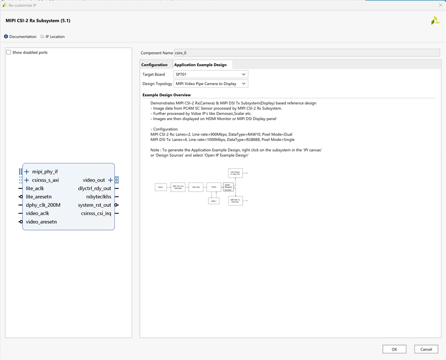
The RAW video data is then converted into RGB data using the Demosaic IP two pixels at a time.
The Xilinx LogiCORE IP Sensor Demosaic core provides an optimized hardware block that reconstructs sub-sampled color data for images captured by a Bayer image sensor. The color filter array overlaid on the silicon substrate enables CMOS or CCD image sensors to measure local light intensities that correspond to different wavelengths. However, the sensor measures the intensity of one principal color at any location. The Sensor Demosaic IP provides an efficient and low-footprint solution to interpolate the missing color components for every pixel.


The AXI4-Stream data is sent to the AXI Switch or AXI Stream Interconnect
The AXI4-Stream Interconnect IP core enables the connection of heterogeneous master/slave AMBA AXI4-Stream protocol compliant endpoint IP.
The AXI4-Stream Interconnect routes connections from one or more AXI4-Stream master channels to one or more AXI4-Stream slave channels

Then broadcast the stream to MIPI DSI TX Subsystem
The Mobile Industry Processor Interface (MIPI) Display Serial Interface (DSI) Transmitter Subsystem implements a DSI transmit interface in adherence to the MIPI DSI standard v1.3 (Type 4 architecture).
The subsystem receives a pixel stream from an AXI4-Stream interface and inserts the required markers (such as hsync start, hsync end) in accordance to the DSI protocol and user programmed options.
The packet framed is sent over an MIPI DPHY (Compliant to MIPI Alliance Standard for D-PHY Specification, version 1.2.) transmitter based on the number of lanes selected.
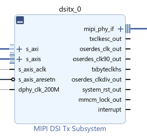
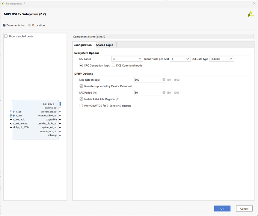
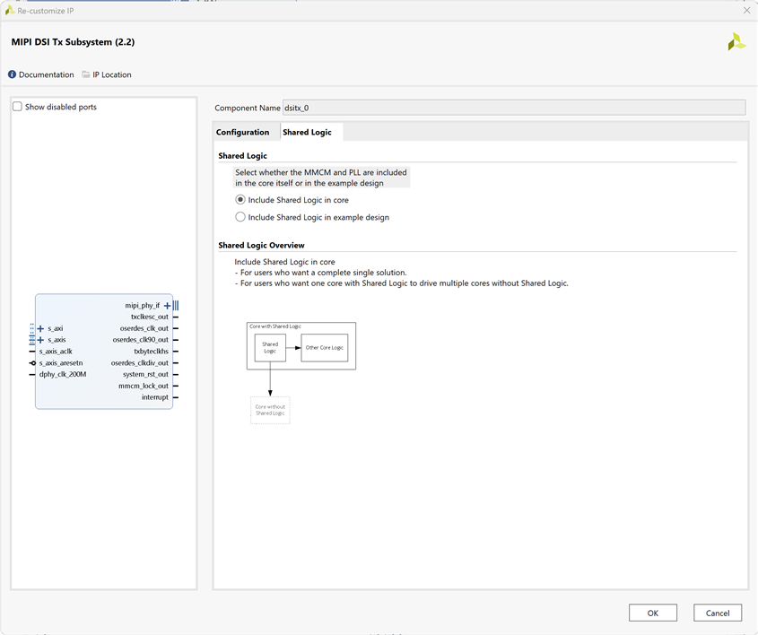
Or broadcast the AXI4 Stream to Video Out Subsystem depending on the user selection
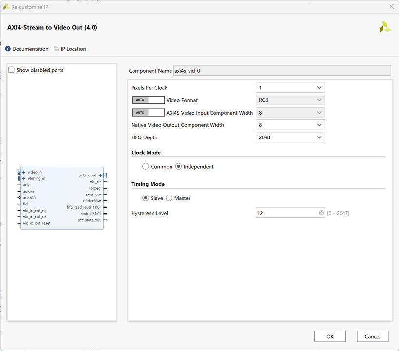
The Xilinx LogiCORE IP AXI4-Stream to Video Out core is designed to interface from the AXI4-Stream interface implementing a Video Protocol to a video source (parallel video data, video syncs, and blanks).This core works with the Xilinx Video Timing Controller (VTC) core. This core provides a bridge between video processing cores with AXI4-Stream interfaces and a video output.
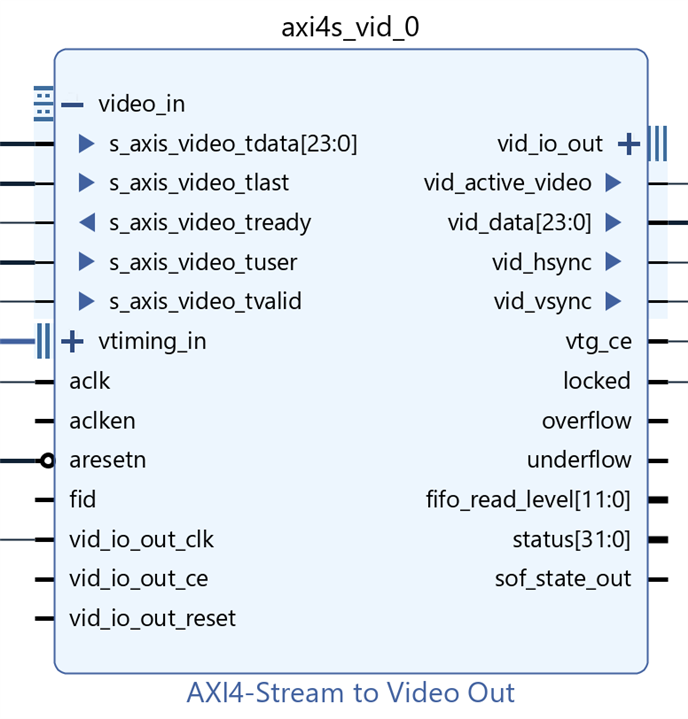
The Video Test Pattern Generator IP (V-TPG) is available in the HDMI Path to act as an alternate source of video in case no MIPI CSI-2 video source is present.
The Xilinx® LogiCORE IP Video Test Pattern Generator core generates test patterns for video system bring up, evaluation, and debugging.
The core provides a wide variety of tests patterns enabling you to debug and assess video system color, quality, edge, and motion performance.
The core can be inserted in an AXI4-Stream video interface that allows user-selectable pass-through of system video signals or insertion of test patterns.


The TPG (in pass-through mode) sends video packets across to the AXI4 Stream to Video Out.
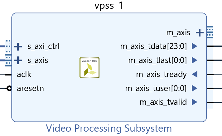
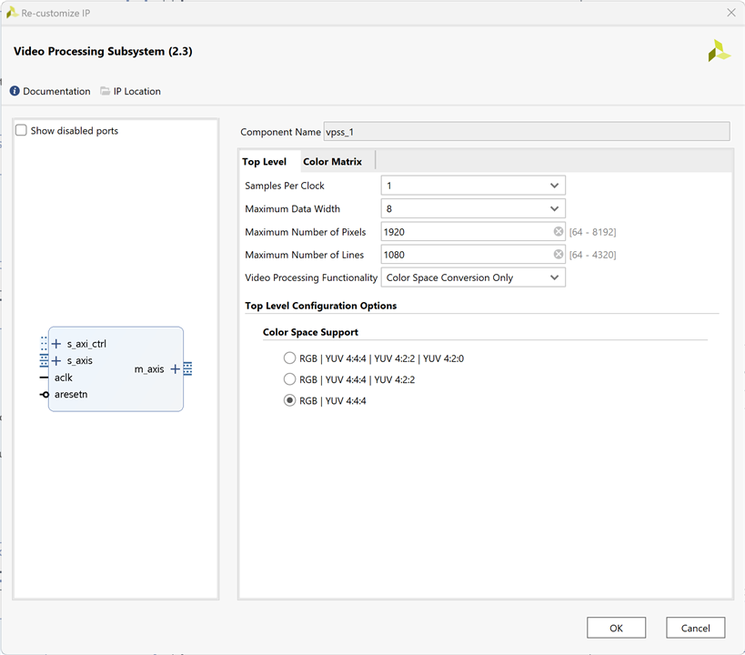
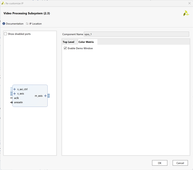
If the MIPI DSI TX Subsystem path is chosen, the video is passed through a video processing subsystem configured as a Scaler.
The Video Processing Subsystem is a collection of video processing IP subcores, bundled together in hardware and software, abstracting the video processing pipe.
It provides the end-user with an out of the box ready to use video processing core, without having to learn about the underlying complexities.
The Video Processing Subsystem enables streamlined integration of various processing blocks including (but not limited to) scaling, deinterlacing, color space conversion and correction, chroma resampling, and frame rate conversion.
The MIPI DSI Panel works on a fixed resolution of 1920x1200. The video must be up scaled (1080p) to 1920x1200 resolution for the MIPI DSI display panel.
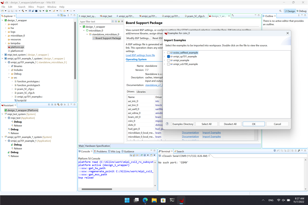
Building the Microblaze App
From the Board Support Package properties window import xmipi_sp701_example for csirx_0
Setup the system
- Connect PCAM 5C Camera Sensor module to the SP701 board "MIPI CSI slot.”
- Connect the HDMI cable to the SP701 HDMI OUT port
- Connect the other end of the HDMI cable to the HDMI monitor.
- Switch on the HDMI monitor and select HDMI as input source if needed
- Connect the USB-JTAG programming cable from the host PC to the board JTAG micro USB port.
- Ensure that all SW6 switches are set to the ON position to allow programming from JTAG.
- Connect the USB UART and JTAG programming cables to the Windows host computer.
- Connect the power supply cable and turn on the SP701 board.
- Program the FPGA from Vitis or Vivado.
- Start a Hyper Terminal program on the host PC with the following settings:
- Baud rate: 9600
- Data Bits: 8
- Parity: None
- Stop Bits: 1
- Flow Control: None

UART Output
The app uses a serial console as user interface.
******************************************************
** SP701 Example Design **
After XIic_DynInit
ADV7511 IIC programming PASSED
IIC Initializtion Done
FMC Interrupt System Initialization Done
IIC Interrupt Handlers Setup Done
Fmc IIC Address Set
Adapter Interrupt System Initialization Done
Adapter IIC Address Set
Reset Done
Sensor is PreConfigured
------ SUBSYSTEM INPUT/OUTPUT CONFIG ------
->INPUT
Color Format: RGB
Color Depth: 0
Pixels Per Clock: 0
Mode: Progressive
Frame Rate: 60Hz
Resolution: 720x480@60Hz (I)
Pixel Clock: 13513 kHz
->OUTPUT
Color Format: RGB
Color Depth: 0
Pixels Per Clock: 0
Mode: Progressive
Frame Rate: 60Hz
Resolution: 720x480@60Hz (I)
Pixel Clock: 13513 kHz
Pipeline Configuration Completed
Please Select option(1 or 2) + ENTER:
1 -> PCAM 5C to DSI Display Panel
2 -> PCAM 5C to HDMI
You can select the active output: DSI or HDMI
SDK Microblaze Application Source code
Device initialization, user interface by UART console and application orchestration by the Microblaze soft processor.
/******************************************************************************
* Copyright (C) 2018 - 2020 Xilinx, Inc.  All rights reserved.
* SPDX-License-Identifier: MIT
*******************************************************************************/

/*****************************************************************************/
/**
*
* @file xmipi_sp701_example.c
*
* <pre>
* MODIFICATION HISTORY:
*
* Ver   Who    Date     Changes
* ----- ------ -------- --------------------------------------------------
* X.XX  XX     YY/MM/DD
* 1.00  RHe    19/09/20 Initial release.
* </pre>
*
******************************************************************************/
/***************************** Include Files *********************************/

#include "xparameters.h"
#include "xiic.h"
#include "xil_exception.h"
#include "function_prototype.h"
#include "pcam_5C_cfgs.h"
#include "xstatus.h"
#include "sleep.h"
#include "xiic_l.h"
#include "xil_io.h"
#include "xil_types.h"
#include "xv_tpg.h"
#include "xil_cache.h"
#include "stdio.h"


/************************** Constant Definitions *****************************/


#define PAGE_SIZE   16


#define IIC_BASE_ADDRESS	XPAR_IIC_2_BASEADDR

#define EEPROM_TEST_START_ADDRESS	0x80

#define IIC_SWITCH_ADDRESS 0x74
#define IIC_ADV7511_ADDRESS 0x39

typedef u8 AddressType;

typedef struct {
	u8 addr;
	u8 data;
	u8 init;
} HDMI_REG;

#define NUMBER_OF_HDMI_REGS  16
HDMI_REG hdmi_iic[NUMBER_OF_HDMI_REGS] = {
	{0x41, 0x00, 0x10},
	{0x98, 0x00, 0x03},
	{0x9A, 0x00, 0xE0},
	{0x9C, 0x00, 0x30},
	{0x9D, 0x00, 0x61},
	{0xA2, 0x00, 0xA4},
	{0xA3, 0x00, 0xA4},
	{0xE0, 0x00, 0xD0},
	{0xF9, 0x00, 0x00},
	{0x18, 0x00, 0xE7},
    {0x55, 0x00, 0x00},
    {0x56, 0x00, 0x28},
    {0xD6, 0x00, 0xC0},
    {0xAF, 0x00, 0x4},
	{0xF9, 0x00, 0x00}
};

u8 EepromIicAddr;		/* Variable for storing Eeprom IIC address */

int IicLowLevelDynEeprom();

u8 EepromReadByte(AddressType Address, u8 *BufferPtr, u8 ByteCount);
u8 EepromWriteByte(AddressType Address, u8 *BufferPtr, u8 ByteCount);


/****************i************ Type Definitions *******************************/

typedef u8 AddressType;

/************************** Variable Definitions *****************************/

extern XIic IicFmc, IicAdapter ;	/*  IIC device. */

//HDMI IIC
int IicLowLevelDynEeprom()
{
  u8 BytesRead;
  u32 StatusReg;
  u8 Index;
  int Status;
  u32 i;
  EepromIicAddr = IIC_SWITCH_ADDRESS;
  Status = XIic_DynInit(IIC_BASE_ADDRESS);
  if (Status != XST_SUCCESS) {
	return XST_FAILURE;
  }
  xil_printf("\r\nAfter XIic_DynInit\r\n");
  while (((StatusReg = XIic_ReadReg(IIC_BASE_ADDRESS,
				XIIC_SR_REG_OFFSET)) &
				(XIIC_SR_RX_FIFO_EMPTY_MASK |
				XIIC_SR_TX_FIFO_EMPTY_MASK |
				XIIC_SR_BUS_BUSY_MASK)) !=
				(XIIC_SR_RX_FIFO_EMPTY_MASK |
				XIIC_SR_TX_FIFO_EMPTY_MASK)) {

  }


  EepromIicAddr = IIC_ADV7511_ADDRESS;
  for ( Index = 0; Index < NUMBER_OF_HDMI_REGS; Index++)
  {
    EepromWriteByte(hdmi_iic[Index].addr, &hdmi_iic[Index].init, 1);
  }

  for ( Index = 0; Index < NUMBER_OF_HDMI_REGS; Index++)
  {
    BytesRead = EepromReadByte(hdmi_iic[Index].addr, &hdmi_iic[Index].data, 1);
    for(i=0;i<1000;i++) {};	// IIC delay
	if (BytesRead != 1) {
      return XST_FAILURE;
	}
  }


  return XST_SUCCESS;

}


/*****************************************************************************/
/**
* This function writes a buffer of bytes to the IIC serial EEPROM.
*
* @param	BufferPtr contains the address of the data to write.
* @param	ByteCount contains the number of bytes in the buffer to be
*		written. Note that this should not exceed the page size of the
*		EEPROM as noted by the constant PAGE_SIZE.
*
* @return	The number of bytes written, a value less than that which was
*		specified as an input indicates an error.
*
* @note		one.
*
******************************************************************************/
u8 EepromWriteByte(AddressType Address, u8 *BufferPtr, u8 ByteCount)
{
  u8 SentByteCount;
  u8 WriteBuffer[sizeof(Address) + PAGE_SIZE];
  u8 Index;

  /*
   * A temporary write buffer must be used which contains both the address
   * and the data to be written, put the address in first based upon the
   * size of the address for the EEPROM
   */
  if (sizeof(AddressType) == 2) {
	WriteBuffer[0] = (u8) (Address >> 8);
	WriteBuffer[1] = (u8) (Address);
  } else if (sizeof(AddressType) == 1) {
	WriteBuffer[0] = (u8) (Address);
	EepromIicAddr |= (EEPROM_TEST_START_ADDRESS >> 8) & 0x7;
  }

  /*
   * Put the data in the write buffer following the address.
   */
  for (Index = 0; Index < ByteCount; Index++) {
	WriteBuffer[sizeof(Address) + Index] = BufferPtr[Index];
  }

  /*
   * Write a page of data at the specified address to the EEPROM.
   */
  SentByteCount = XIic_DynSend(IIC_BASE_ADDRESS, EepromIicAddr,
				WriteBuffer, sizeof(Address) + ByteCount,
				XIIC_STOP);

  /*
   * Return the number of bytes written to the EEPROM.
   */
  return SentByteCount - sizeof(Address);

}


/******************************************************************************
*
* This function reads a number of bytes from the IIC serial EEPROM into a
* specified buffer.
*
* @param	BufferPtr contains the address of the data buffer to be filled.
* @param	ByteCount contains the number of bytes in the buffer to be read.
*		This value is constrained by the page size of the device such
*		that up to 64K may be read in one call.
*
* @return	The number of bytes read. A value less than the specified input
*		value indicates an error.
*
* @note		None.
*
******************************************************************************/
u8 EepromReadByte(AddressType Address, u8 *BufferPtr, u8 ByteCount)
{
  u8 ReceivedByteCount;
  u8 SentByteCount;
  u16 StatusReg;

  /*
   * Position the Read pointer to specific location in the EEPROM.
   */
  do {
	StatusReg = XIic_ReadReg(IIC_BASE_ADDRESS, XIIC_SR_REG_OFFSET);
    if (!(StatusReg & XIIC_SR_BUS_BUSY_MASK)) {
	  SentByteCount = XIic_DynSend(IIC_BASE_ADDRESS, EepromIicAddr,
					  (u8 *) &Address, sizeof(Address), XIIC_REPEATED_START);
    }

  } while (SentByteCount != sizeof(Address));
  /*
   * Receive the data.
   */
  ReceivedByteCount = XIic_DynRecv(IIC_BASE_ADDRESS, EepromIicAddr,
		                                          BufferPtr, ByteCount);

  /*
   * Return the number of bytes received from the EEPROM.
   */

  return ReceivedByteCount;

}


/*****************************************************************************/
/**
 *
 * Main function to initialize interop system and read data from AR0330 sensor

 * @param  None.
 *
 * @return
 *   - XST_SUCCESS if MIPI Interop was successful.
 *   - XST_FAILURE if MIPI Interop failed.
 *
 * @note   None.
 *
 ******************************************************************************/
int main() {
  int Status;
  int pcam5c_mode = 1;
  int usr_entry ,prev_sel;
  int default_input;
  int dsi_hdmi_select = 0;

  xil_printf("\n\r******************************************************\n\r");
  Xil_ICacheDisable();
  Xil_DCacheDisable();
  xil_printf("\n\r**           SP701 Example Design            **");

  Status = IicLowLevelDynEeprom();
  if (Status != XST_SUCCESS) {
    xil_printf("ADV7511 IIC programming FAILED\r\n");
    return XST_FAILURE;
  }
  xil_printf("ADV7511 IIC programming PASSED\r\n");


  //Initialize FMC, Adapter and Sensor IIC
  Status = InitIIC();
  if (Status != XST_SUCCESS) {
	xil_printf("\n\r IIC initialization Failed \n\r");
	return XST_FAILURE;
  }
  xil_printf("IIC Initializtion Done \n\r");

  //Initialize FMC Interrupt System
  Status = SetupFmcInterruptSystem(&IicFmc);
  if (Status != XST_SUCCESS) {
    xil_printf("\n\rInterrupt System Initialization Failed \n\r");
    return XST_FAILURE;
  }
  xil_printf("FMC Interrupt System Initialization Done \n\r");

  //Set up IIC Interrupt Handlers
  SetupIICIntrHandlers();
  xil_printf("IIC Interrupt Handlers Setup Done \n\r");

  Status =  SetFmcIICAddress();
  if (Status != XST_SUCCESS) {
    xil_printf("\n\rFMC IIC Address Setup Failed \n\r");
	return XST_FAILURE;
  }
  xil_printf("Fmc IIC Address Set\n\r");

  //Initialize Adapter Interrupt System
  Status = SetupAdapterInterruptSystem(&IicAdapter);
  if (Status != XST_SUCCESS) {
    xil_printf("\n\rInterrupt System Initialization Failed \n\r");
    return XST_FAILURE;
  }
  xil_printf("Adapter Interrupt System Initialization Done \n\r");

  //Set Address of Adapter IIC
  Status =  SetAdapterIICAddress();
  if (Status != XST_SUCCESS) {
    xil_printf("\n\rAdapter IIC Address Setup Failed \n\r");
	return XST_FAILURE;
  }
  xil_printf("Adapter IIC Address Set\n\r");

  Status = InitializeCsiRxSs();
  if (Status != XST_SUCCESS) {
    xil_printf("CSI Rx Ss Init failed status = %x.\r\n", Status);
	return XST_FAILURE;
  }


  dsi_hdmi_select = 0;
  //using default_input var to compare same option selection
  default_input = 1;
  SetupDSI();
  resetIp();
  EnableCSI();
  GPIOSelect(dsi_hdmi_select);

  Status = demosaic();
  if (Status != XST_SUCCESS) {
	xil_printf("\n\rDemosaic Failed \n\r");
	return XST_FAILURE;
  }

  CamReset();

  //Preconifgure Sensor
  Status = SensorPreConfig(pcam5c_mode);
  if (Status != XST_SUCCESS) {
	xil_printf("\n\rSensor PreConfiguration Failed \n\r");
	return XST_FAILURE;
  }
  xil_printf("\n\rSensor is PreConfigured\n\r");

  Status = vdma_hdmi();
  if (Status != XST_SUCCESS) {
    xil_printf("\n\rVdma_hdmi Failed \n\r");
	return XST_FAILURE;
  }

  Status = vtpg_hdmi();
  if (Status != XST_SUCCESS) {
    xil_printf("\n\rVtpg Failed \n\r");
	return XST_FAILURE;
  }

  WritetoReg(0x30, 0x08, 0x02);
  Sensor_Delay();
  xil_printf("\n\rPipeline Configuration Completed \n\r");

  while(1) {

    xil_printf("\r\nPlease Select option(1 or 2) + ENTER:");
    xil_printf("\r\n    1 -> PCAM 5C to DSI Display Panel");
    xil_printf("\r\n    2 -> PCAM 5C to HDMI\r\n");

    usr_entry = getchar();

    char b;
    scanf("%c", &b);// This will take ENTER key

    if (prev_sel == usr_entry) {
      xil_printf("\r\nAlready in the selected option. Please try again\n");
      continue;
    }
    prev_sel = usr_entry;


	switch(usr_entry) {

	  case '1':
		xil_printf("\n\rSwitching to DSI\n\r");
		dsi_hdmi_select = 1;
		SetupDSI();
		resetIp();
		InitDSI();
		EnableCSI();
		GPIOSelect(dsi_hdmi_select);
		default_input = 0;

		Status = demosaic();
		if (Status != XST_SUCCESS) {
		  xil_printf("\n\rDemosaic Failed \n\r");
		  return XST_FAILURE;
		}

		CamReset();

		//Preconifgure Sensor
		Status = SensorPreConfig(pcam5c_mode);
		if (Status != XST_SUCCESS) {
		  xil_printf("\n\rSensor PreConfiguration Failed \n\r");
		  return XST_FAILURE;
		}
		xil_printf("\n\rSensor is PreConfigured\n\r");

		Status = vdma_dsi();
		if (Status != XST_SUCCESS) {
		  xil_printf("\n\rVdma_dsi Failed \n\r");
		  return XST_FAILURE;
		}
		WritetoReg(0x30, 0x08, 0x02);
		Sensor_Delay();
		xil_printf("\n\rPipeline Configuration Completed \n\r");

		break;

	  case '2':

		if (default_input == 1) {
		  xil_printf("\r\nAlready in the selected option. Please try again\n");
		  default_input = 0;
		  continue;
		}
		xil_printf("\n\rSwitching to HDMI\n\r");
		dsi_hdmi_select = 0;
		resetIp();
	    SetupDSI();
	    EnableCSI();
	    GPIOSelect(dsi_hdmi_select);

	    Status = demosaic();
		if (Status != XST_SUCCESS) {
          xil_printf("\n\rDemosaic Failed \n\r");
		  return XST_FAILURE;
	    }

		CamReset();

		//Preconifgure Sensor
		Status = SensorPreConfig(pcam5c_mode);
		if (Status != XST_SUCCESS) {
	      xil_printf("\n\rSensor PreConfiguration Failed \n\r");
	      return XST_FAILURE;
		}
		xil_printf("\n\rSensor is PreConfigured\n\r");

		Status = vdma_hdmi();
		if (Status != XST_SUCCESS) {
	      xil_printf("\n\rVdma_hdmi Failed \n\r");
	      return XST_FAILURE;
	    }

		Status = vtpg_hdmi();
		if (Status != XST_SUCCESS) {
		  xil_printf("\n\rVtpg Failed \n\r");
		  return XST_FAILURE;
		}
		WritetoReg(0x30, 0x08, 0x02);
		Sensor_Delay();
		xil_printf("\n\rPipeline Configuration Completed \n\r");

		break;

	  default:
        xil_printf("\n\rSelection is unavailable. Please try again\n\r");
	    break;
	}

  }
  return XST_SUCCESS;

}
Using a USB Video Capture Dongle
For the last video examples I have used a USB video capture device connected to the PC. The HDMI output of the SP701 board connects to the USB video capture HDMI dongle connector.

Capturing HDMI output with a USB Video Capture Dongle:
Using the system as a USB webcam
Block design in pdf
Related documents and links
Conclusions
Xilinx provides an example for MIPI IP Cores that allows you to have a working solution in minutes.
The Pcam 5C can only be controlled by a SoC with a MIPI CSI-2 controller in hardware and using these breakouts requires complicated software that correctly configures the controller and sensor.
Xilinx provides a very robust solution and good software support but there are associated license costs. The IP cores provided are encrypted and it is not possible to study how they are built.
Next Steps
The next step is going to be to start working with the video mixer IP core and creating hardware accelerated overlays designed with Vitis HLS.

I have already started creating hardware accelerated overlays to display the measurements on the screen in real time, at the moment based on a solution by Adam Taylor on Vitis HLS but adapted to the Vitis Vision library. I had problems with the version of Vivado 2021.1 for Windows OS that is not able to synthesize the Video Mixer, but after updating to the version of Vivado 2022.1 or Vivado 2022.2 everything is solved.
The Complete "Sensor Fusion for Firefighters" Blog Series
- Sensor Fusion for Firefighters. Introductory blog
- Sensor Fusion for Firefighters. Getting Started with the AMD Xilinx SP701
- Sensor Fusion for Firefighters. AMD Xilinx SP701 - MIPI Video Pipe Camera to HDMI Display
- Sensor Fusion for Firefighters. Displaying heads-up video on the live feed
- Sensor Fusion for Firefighters. Environmental monitor heads-up display on Xilinx Spartan-7 SP701 development board
- Sensor Fusion for Firefighters. Compass and Environmental HUD monitor with the Spartan-7
- Sensor Fusion for Firefighters. Thermal Vision, Compass and Environmental HUD monitor with the Spartan-7
- Sensor Fusion for Firefighters. Summary Blog


Top Comments