


In this blog, I rebuild from scratch the demo application from the Spartan-7 SP701 FPGA Evaluation Kit Demo Project designed by Adam Taylor (adamtaylorcengfiet). The challenging element of that project is to show a Heads-Up display during the live broadcast of the video captured by the Pcam 5C camera. Live video is stored within the external DDR. Thus, the Xilinx MicroBlaze processor could access the frame store at DDR memory and render the heads up display (HUD). However, this is computationally intensive and as such the MicroBlaze processor is not capable of keeping up with the 60fps frame rate. Therefore, a custom HLS block is created to represent the HUD. This takes the heavy processing out of the MicroBlaze soft processor, so you only have to tell the HUD what to render on the AXI interface.
References:
- Spartan-7 SP701 FPGA Evaluation Kit Demonstration Project
- MicroZed Chronicles (adiuvoengineering.com)
Table of Contents
The Complete "Sensor Fusion for Firefighters" Blog Series
- Sensor Fusion for Firefighters. Introductory blog
- Sensor Fusion for Firefighters. Getting Started with the AMD Xilinx SP701
- Sensor Fusion for Firefighters. AMD Xilinx SP701 - MIPI Video Pipe Camera to HDMI Display
- Sensor Fusion for Firefighters. Displaying heads-up video on the live feed
- Sensor Fusion for Firefighters. Environmental monitor heads-up display on Xilinx Spartan-7 SP701 development board
- Sensor Fusion for Firefighters. Compass and Environmental HUD monitor with the Spartan-7
- Sensor Fusion for Firefighters. Thermal Vision, Compass and Environmental HUD monitor with the Spartan-7
- Sensor Fusion for Firefighters. Summary Blog
Adam Taylor HUD Demo Rebuild
Motivation: Virtual 7-Segment Display
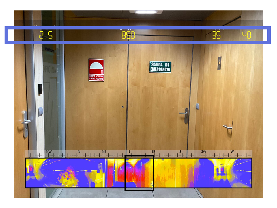
In my work plan I have planned to create a monitor with several virtual 7-segment display modules. In total, the module will have the capacity to display 16 digits of 7 segments in real time, grouped into four different modules, in order to display four different sensor measurements. In addition, this layer will have a graduated linear axis of the magnetic compass that will indicate the current magnetic orientation detected by the magnetometer.
The Spartan-7 SP701 FPGA Evaluation Kit Demo Project designed by Adam Taylor is a good reference to learn about the video mixers and video overlays. I'm going to study the Adam Taylor's example, rebuilding the example from scratch and updating it with the latest version of Vivado and the latest versions of the imaging processiong IPs included in Vivado and Vitis HLS.
The custom HUD HLS IP Block
The HUD HLS IP Block is responsible for generating the AXI video stream overlay.
First you have to create the HUD IP block. This is done with Vitis HLS. I've used Vitis HLS versions 2022.2 and 2022.1
You can download Adam Taylor's code from his Github repository: GitHub - ATaylorCEngFIET/HUD: HLS Implementation of a HUD for image processing systems.
Then create a new project in Vitis HLS. The HUD IP core interfaces with the MicroBlaze soft processor over the AXI4-Lite and with the image-processing system using AXI Stream. AXI4-Lite is a basic AXI communication protocol. It is often used for simple, low-throughput memory-mapped communication (for example, to and from control and status registers).
The source code consists of three flies:
- hud.cpp & hud.h : This is the code that will be synthesized into RTL in order to create the IP. This IP will be combined with other IP in the Vivado Design Suite, and eventually placed on your hardware. The main function is hud_gen.
- char.h: digits "font" as bidimensional 11x10 arrays
And a test bench:
- tb.cpp: This is the testbench we will use to make sure hud.cpp works as expected. This testbench enables the output image to be captured in black and white, showing the border of the image and display of the characters. This file uses OpenCV to be able to "visualize" the results before synthesis. I am going to modify this file so that it does not depend on the OpenCV installation.
You can export the RTL as a packed IP without using the test bench.
hud.h modifications
For porting to Vivado 2022 the hud.h header file requires only two modifications:
- change #include "hls_video.h" to #include "hls_stream.h"
- and then add #include "ap_axi_sdata.h"
#include "hls_stream.h"
#include "ap_axi_sdata.h"
#include <ap_fixed.h>
#include "string.h"

#define WIDTH 32


typedef hls::stream<ap_axiu<WIDTH,1,1,1> > axis;
typedef ap_axiu<WIDTH,1,1,1> video_stream;

void hud_gen(axis& op, int row, int column, int char_1, int char_2) ;
The other two files don't need any change.
tb.cpp modifications
tb.cp is the test bench file that uses OpenCV. You can install OpenCV and in project settings set the include path and the paths for the linker or do like me.
I have modified the test bench to not depend on OpenCV including a couple of functions to store the result as bitmap.
#include "hud.h"
#include <iostream>
using namespace std;

#include <stdio.h>

const int BYTES_PER_PIXEL = 3; /// red, green, & blue
const int FILE_HEADER_SIZE = 14;
const int INFO_HEADER_SIZE = 40;

void generateBitmapImage(unsigned char* image, int height, int width, char* imageFileName);
unsigned char* createBitmapFileHeader(int height, int stride);
unsigned char* createBitmapInfoHeader(int height, int width);
void AXIvideo2Bmp(axis& AXI_video_strm, int h, int w );

int main (int argc, char** argv) {
	axis  dst_axi;
	cout << "Starting simulation..!\r\n";
	hud_gen(dst_axi, 1080, 1920, 8, 7);
	AXIvideo2Bmp(dst_axi, 1080, 1920);
	cout << "Finished!\r\n";
	return 0;
}

void AXIvideo2Bmp(axis& AXI_video_strm, int h, int w ) {
	int i, j;
	ap_axiu<WIDTH,1,1,1> axi;
	bool sof = 0;

	int y, x;
	FILE *f;
	unsigned char *img = NULL;
	int filesize = 54 + 3*w*h;  //w is your image width, h is image height, both int

	img = (unsigned char *)malloc(3*w*h);
	memset(img,0,3*w*h);
	for (i = 0; i < h; i++) {
		for (j = 0; j < (w); j++) {
			AXI_video_strm >> axi;
			if ((i == 0) && (j == 0)) {
				if (axi.user.to_int() == 1) {
					sof = 1;
				} else {
					j--;
				}
			}
			if (sof) {
				x=j; y=i;
				if (axi.data== 0) {
					img[(x+y*w)*3+2] = 0;
					img[(x+y*w)*3+1] = 0;
					img[(x+y*w)*3+0] = 0;
				} else {
				    // RGBA to RGB Bitmap
				    img[(x+y*w)*3+2] = (unsigned char) (axi.data >> 16) & 0xFF; /// red
					img[(x+y*w)*3+1] = (unsigned char) (axi.data      ) & 0xFF; /// green
					img[(x+y*w)*3+0] = (unsigned char) (axi.data >>  8) & 0xFF; /// blue
				}
			}
		}

	}
    // BM Windows 3.1x, 95, NT, ... etc.
    // 54 The offset of the byte where the bitmap image data (pixel array) can be found.
	unsigned char bmpfileheader[14] = {'B','M', 0,0,0,0, 0,0, 0,0, 54,0,0,0};
	//BITMAPINFOHEADER Windows NT, 3.1x or later[2]
	// 40 the size of this header, in bytes
	// 1 color plane
	// bits per pixel 24
	unsigned char bmpinfoheader[40] = {40,0,0,0, 0,0,0,0, 0,0,0,0, 1,0, 24,0};
	unsigned char bmppad[3] = {0,0,0};
    // The size of the BMP file in bytes
	bmpfileheader[ 2] = (unsigned char)(filesize    );
	bmpfileheader[ 3] = (unsigned char)(filesize>> 8);
	bmpfileheader[ 4] = (unsigned char)(filesize>>16);
	bmpfileheader[ 5] = (unsigned char)(filesize>>24);
    // the bitmap width in pixels (signed integer)
	bmpinfoheader[ 4] = (unsigned char)(       w    );
	bmpinfoheader[ 5] = (unsigned char)(       w>> 8);
	bmpinfoheader[ 6] = (unsigned char)(       w>>16);
	bmpinfoheader[ 7] = (unsigned char)(       w>>24);
	// the bitmap height in pixels (signed integer)
	bmpinfoheader[ 8] = (unsigned char)(       h    );
	bmpinfoheader[ 9] = (unsigned char)(       h>> 8);
	bmpinfoheader[10] = (unsigned char)(       h>>16);
	bmpinfoheader[11] = (unsigned char)(       h>>24);

	f = fopen("img.bmp","wb");
	fwrite(bmpfileheader,1,14,f);
	fwrite(bmpinfoheader,1,40,f);
	for(int i=0; i<h; i++)
	{
		fwrite(img+(w*(h-i-1)*3),3,w,f);
		fwrite(bmppad,1,(4-(w*3)%4)%4,f);
	}

	free(img);
	fclose(f);
}
This is the ouput bitmap for the test when calling the main function as
hud_gen(dst_axi, 1080, 1920, 8, 7):

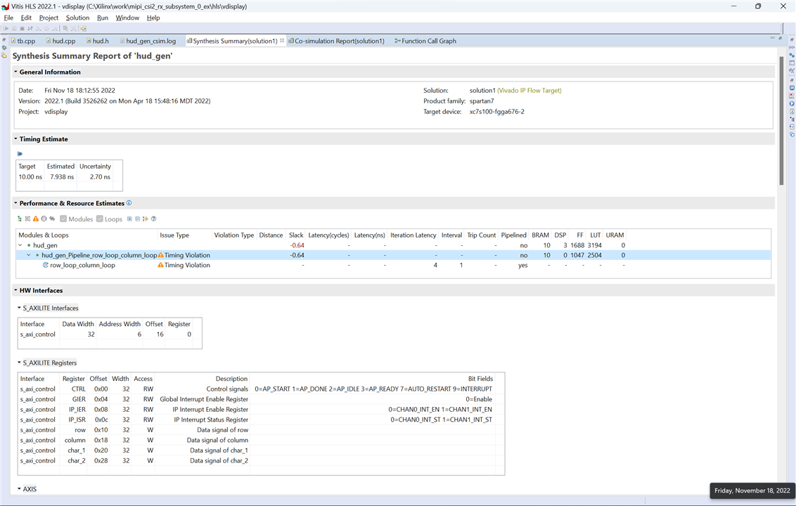
We can now tell Vitis HLS to run the synthesis.
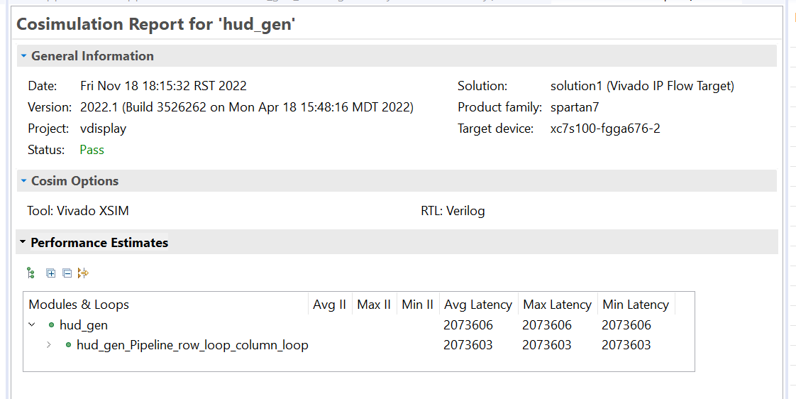
And the cosimulation:
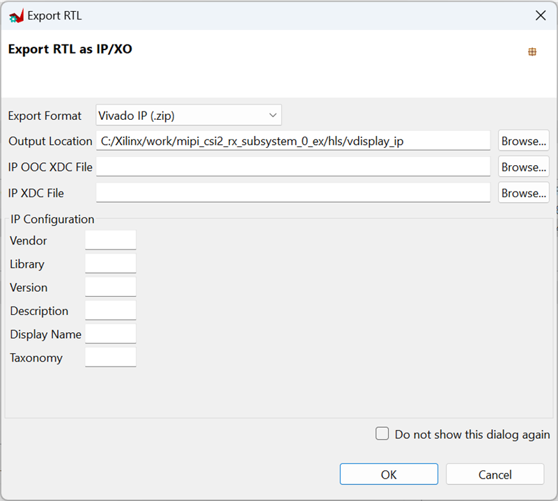
And export the RTL package:
Block Design
Now from Vivado 2022.1 or Vivado 2022.2 we can open the reference project that I created in the previous blog: AMD Xilinx SP701 - MIPI Video Pipe Camera to HDMI Display
First import the new IP
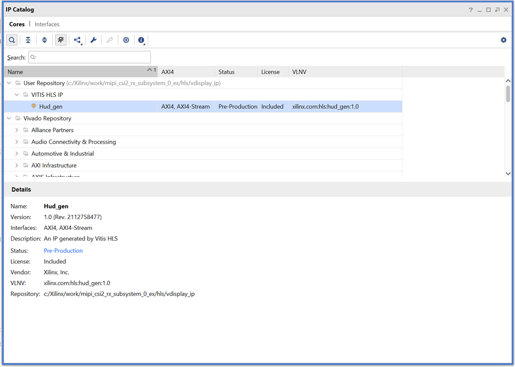
Then open the Block Design:
Add a Video Mixer IP and configure one RGBA Stream Layer for the HUD
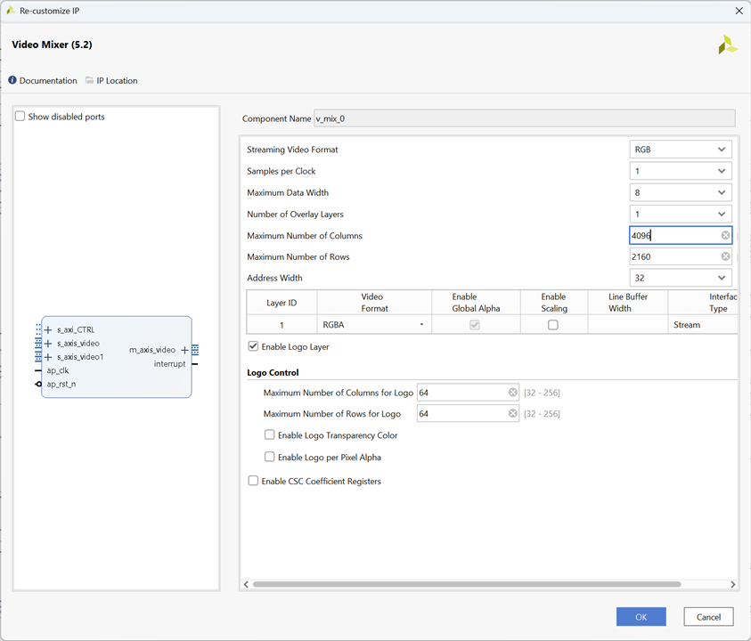
We don't need the Logo Layer. The HUD IP output will be connected to the Layer ID 1 as an AXI Stream.
Add the HUD IP and connect as in the diagram.
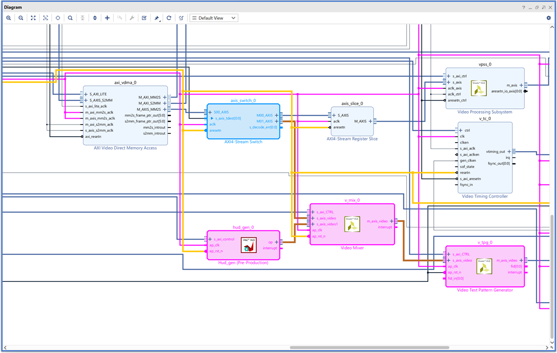
You will need to increment the master interfaces of the AXI Interconnect or modify the ones that are unconnected. As we want these two Master Interfaces to have the same clock a reset signals than the rest of our video processing pipe, I found easier to add two more and manually connect reset and clock signals. Then you can make the rest of the connections as in the above figure. For connecting to the AXI Interconnect let Vivado run the automation routines and then change the AXI connections to the new ones.
Here is the complete block design:
Then you can generate the bitstream:
Export the hardware as .xsa including the bistream.
MicroBlaze bare metal application
Now from VITIS IDE we'll make a live displaying a counter overlay on the live feed.
You can start with the MIPI rx SP701 reference example. See previous blog: Sensor Fusion for Firefighters. AMD Xilinx SP701 - MIPI Video Pipe Camera to HDMI Display
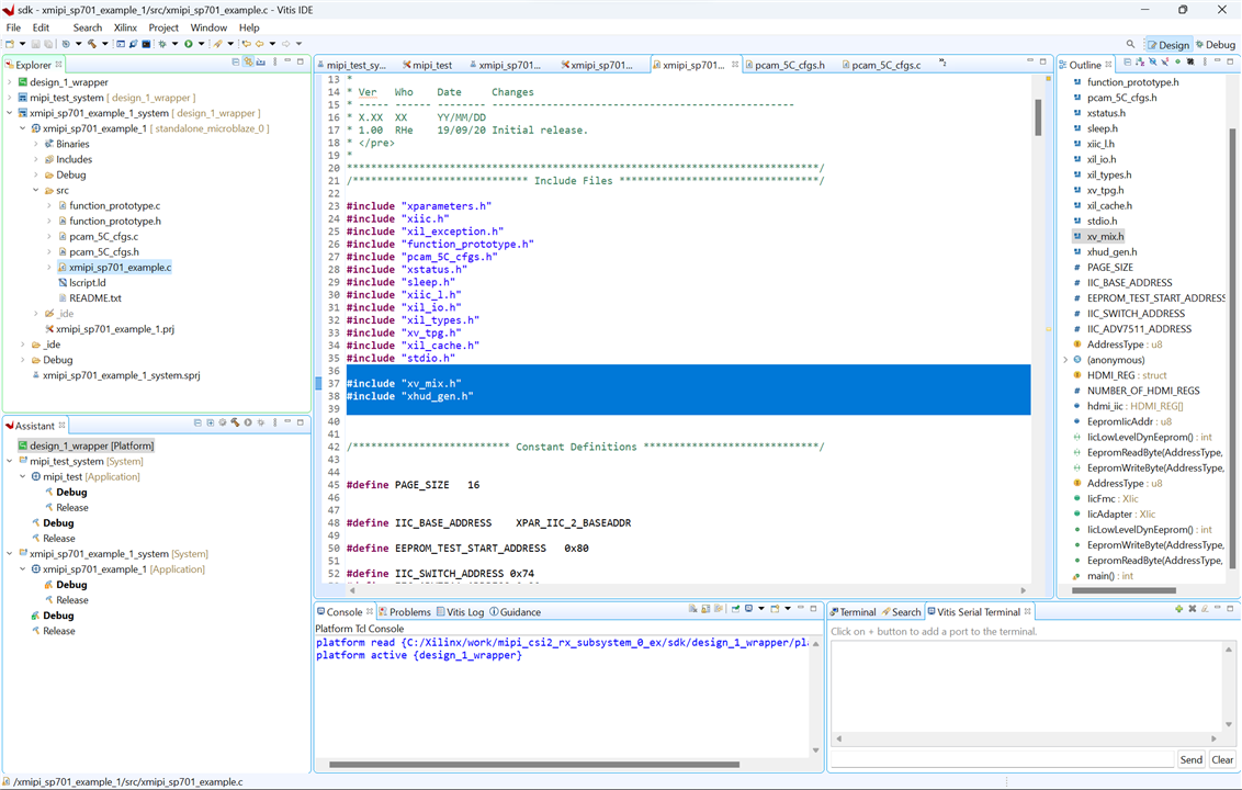
I needed update the platform hardware specification with the new .xsa and replace the mipi_sp701_example.c in the application project with this code:
/******************************************************************************
 * Copyright (C) 2018 - 2022 Xilinx, Inc.  All rights reserved.
 * SPDX-License-Identifier: MIT
 *******************************************************************************/

/*****************************************************************************/
/**
 *
 * @file xmipi_sp701_example.c
 *
 * <pre>
 * MODIFICATION HISTORY:
 *
 * Ver   Who    Date     Changes
 * ----- ------ -------- --------------------------------------------------
 * X.XX  XX     YY/MM/DD
 * 1.00  RHe    19/09/20 Initial release.
 * </pre>
 *
 ******************************************************************************/
/***************************** Include Files *********************************/

#include "xparameters.h"
#include "xiic.h"
#include "xil_exception.h"
#include "function_prototype.h"
#include "pcam_5C_cfgs.h"
#include "xstatus.h"
#include "sleep.h"
#include "xiic_l.h"
#include "xil_io.h"
#include "xil_types.h"
#include "xv_tpg.h"
#include "xil_cache.h"
#include "stdio.h"

#include "xv_mix.h"
#include "xhud_gen.h"


/************************** Constant Definitions *****************************/


#define PAGE_SIZE   16


#define IIC_BASE_ADDRESS	XPAR_IIC_2_BASEADDR

#define EEPROM_TEST_START_ADDRESS	0x80

#define IIC_SWITCH_ADDRESS 0x74
#define IIC_ADV7511_ADDRESS 0x39

typedef u8 AddressType;

typedef struct {
	u8 addr;
	u8 data;
	u8 init;
} HDMI_REG;

#define NUMBER_OF_HDMI_REGS  16
HDMI_REG hdmi_iic[NUMBER_OF_HDMI_REGS] = {
		{0x41, 0x00, 0x10},
		{0x98, 0x00, 0x03},
		{0x9A, 0x00, 0xE0},
		{0x9C, 0x00, 0x30},
		{0x9D, 0x00, 0x61},
		{0xA2, 0x00, 0xA4},
		{0xA3, 0x00, 0xA4},
		{0xE0, 0x00, 0xD0},
		{0xF9, 0x00, 0x00},
		{0x18, 0x00, 0xE7},
		{0x55, 0x00, 0x00},
		{0x56, 0x00, 0x28},
		{0xD6, 0x00, 0xC0},
		{0xAF, 0x00, 0x4},
		{0xF9, 0x00, 0x00}
};

u8 EepromIicAddr;		/* Variable for storing Eeprom IIC address */

int IicLowLevelDynEeprom();

u8 EepromReadByte(AddressType Address, u8 *BufferPtr, u8 ByteCount);
u8 EepromWriteByte(AddressType Address, u8 *BufferPtr, u8 ByteCount);


/****************i************ Type Definitions *******************************/

typedef u8 AddressType;

/************************** Variable Definitions *****************************/

extern XIic IicFmc, IicAdapter ;	/*  IIC device. */

//HDMI IIC
int IicLowLevelDynEeprom()
{
	u8 BytesRead;
	u32 StatusReg;
	u8 Index;
	int Status;
	u32 i;
	EepromIicAddr = IIC_SWITCH_ADDRESS;
	Status = XIic_DynInit(IIC_BASE_ADDRESS);
	if (Status != XST_SUCCESS) {
		return XST_FAILURE;
	}
	xil_printf("\r\nAfter XIic_DynInit\r\n");
	while (((StatusReg = XIic_ReadReg(IIC_BASE_ADDRESS,
			XIIC_SR_REG_OFFSET)) &
			(XIIC_SR_RX_FIFO_EMPTY_MASK |
					XIIC_SR_TX_FIFO_EMPTY_MASK |
					XIIC_SR_BUS_BUSY_MASK)) !=
							(XIIC_SR_RX_FIFO_EMPTY_MASK |
									XIIC_SR_TX_FIFO_EMPTY_MASK)) {

	}


	EepromIicAddr = IIC_ADV7511_ADDRESS;
	for ( Index = 0; Index < NUMBER_OF_HDMI_REGS; Index++)
	{
		EepromWriteByte(hdmi_iic[Index].addr, &hdmi_iic[Index].init, 1);
	}

	for ( Index = 0; Index < NUMBER_OF_HDMI_REGS; Index++)
	{
		BytesRead = EepromReadByte(hdmi_iic[Index].addr, &hdmi_iic[Index].data, 1);
		for(i=0;i<1000;i++) {};	// IIC delay
		if (BytesRead != 1) {
			return XST_FAILURE;
		}
	}


	return XST_SUCCESS;

}


/*****************************************************************************/
/**
 * This function writes a buffer of bytes to the IIC serial EEPROM.
 *
 * @param	BufferPtr contains the address of the data to write.
 * @param	ByteCount contains the number of bytes in the buffer to be
 *		written. Note that this should not exceed the page size of the
 *		EEPROM as noted by the constant PAGE_SIZE.
 *
 * @return	The number of bytes written, a value less than that which was
 *		specified as an input indicates an error.
 *
 * @note		one.
 *
 ******************************************************************************/
u8 EepromWriteByte(AddressType Address, u8 *BufferPtr, u8 ByteCount)
{
	u8 SentByteCount;
	u8 WriteBuffer[sizeof(Address) + PAGE_SIZE];
	u8 Index;

	/*
	 * A temporary write buffer must be used which contains both the address
	 * and the data to be written, put the address in first based upon the
	 * size of the address for the EEPROM
	 */
	if (sizeof(AddressType) == 2) {
		WriteBuffer[0] = (u8) (Address >> 8);
		WriteBuffer[1] = (u8) (Address);
	} else if (sizeof(AddressType) == 1) {
		WriteBuffer[0] = (u8) (Address);
		EepromIicAddr |= (EEPROM_TEST_START_ADDRESS >> 8) & 0x7;
	}

	/*
	 * Put the data in the write buffer following the address.
	 */
	for (Index = 0; Index < ByteCount; Index++) {
		WriteBuffer[sizeof(Address) + Index] = BufferPtr[Index];
	}

	/*
	 * Write a page of data at the specified address to the EEPROM.
	 */
	SentByteCount = XIic_DynSend(IIC_BASE_ADDRESS, EepromIicAddr,
			WriteBuffer, sizeof(Address) + ByteCount,
			XIIC_STOP);

	/*
	 * Return the number of bytes written to the EEPROM.
	 */
	return SentByteCount - sizeof(Address);

}


/******************************************************************************
 *
 * This function reads a number of bytes from the IIC serial EEPROM into a
 * specified buffer.
 *
 * @param	BufferPtr contains the address of the data buffer to be filled.
 * @param	ByteCount contains the number of bytes in the buffer to be read.
 *		This value is constrained by the page size of the device such
 *		that up to 64K may be read in one call.
 *
 * @return	The number of bytes read. A value less than the specified input
 *		value indicates an error.
 *
 * @note		None.
 *
 ******************************************************************************/
u8 EepromReadByte(AddressType Address, u8 *BufferPtr, u8 ByteCount)
{
	u8 ReceivedByteCount;
	u8 SentByteCount;
	u16 StatusReg;

	/*
	 * Position the Read pointer to specific location in the EEPROM.
	 */
	do {
		StatusReg = XIic_ReadReg(IIC_BASE_ADDRESS, XIIC_SR_REG_OFFSET);
		if (!(StatusReg & XIIC_SR_BUS_BUSY_MASK)) {
			SentByteCount = XIic_DynSend(IIC_BASE_ADDRESS, EepromIicAddr,
					(u8 *) &Address, sizeof(Address), XIIC_REPEATED_START);
		}

	} while (SentByteCount != sizeof(Address));
	/*
	 * Receive the data.
	 */
	ReceivedByteCount = XIic_DynRecv(IIC_BASE_ADDRESS, EepromIicAddr,
			BufferPtr, ByteCount);

	/*
	 * Return the number of bytes received from the EEPROM.
	 */

	return ReceivedByteCount;

}


/*****************************************************************************/
/**
 *
 * Main function to initialize interop system and read data from AR0330 sensor

 * @param  None.
 *
 * @return
 *   - XST_SUCCESS if MIPI Interop was successful.
 *   - XST_FAILURE if MIPI Interop failed.
 *
 * @note   None.
 *
 ******************************************************************************/
int main() {
	int Status;
	int pcam5c_mode = 1;
	int usr_entry ,prev_sel;
	int default_input;
	int dsi_hdmi_select = 0;

	XV_mix xv_mix;
	XV_mix_Config *xv_config;

	XHud_gen_Config *XV_Hud_cfg;
	XHud_gen xv_hud;

	xil_printf("\n\r******************************************************\n\r");
	Xil_ICacheDisable();
	Xil_DCacheDisable();
	xil_printf("\n\r**           SP701 Example Design            **");

	xv_config = XV_mix_LookupConfig(XPAR_XV_MIX_0_DEVICE_ID);
	XV_mix_CfgInitialize(&xv_mix,xv_config,xv_config->BaseAddress);

	XV_mix_Set_HwReg_width(&xv_mix, (u32)1920);
	XV_mix_Set_HwReg_height(&xv_mix, (u32) 1080);
	XV_mix_Set_HwReg_layerEnable(&xv_mix,(u32)3);

	XV_mix_Set_HwReg_layerStartX_0(&xv_mix,(u32)0);
	XV_mix_Set_HwReg_layerStartY_0(&xv_mix,0);
	XV_mix_Set_HwReg_layerWidth_0(&xv_mix,(u32)1920);
	XV_mix_Set_HwReg_layerHeight_0(&xv_mix,(u32)1080);
	XV_mix_Set_HwReg_layerAlpha_0(&xv_mix, 255);

	XV_mix_Set_HwReg_layerStartX_1(&xv_mix,(u32)0);
	XV_mix_Set_HwReg_layerStartY_1(&xv_mix,0);
	XV_mix_Set_HwReg_layerWidth_1(&xv_mix,(u32)1920);
	XV_mix_Set_HwReg_layerHeight_1(&xv_mix,(u32)1080);
	XV_mix_Set_HwReg_layerAlpha_1(&xv_mix, 255);

	XV_mix_EnableAutoRestart(&xv_mix);
	XV_mix_Start(&xv_mix);


	XV_Hud_cfg = XHud_gen_LookupConfig(XPAR_HUD_GEN_0_DEVICE_ID);
	XHud_gen_CfgInitialize(&xv_hud,XV_Hud_cfg);

	XHud_gen_Set_row(&xv_hud, (u32) 1080);
	XHud_gen_Set_column(&xv_hud, (u32) 1920);

	XHud_gen_EnableAutoRestart(&xv_hud);
	XHud_gen_Start(&xv_hud);


	Status = IicLowLevelDynEeprom();
	if (Status != XST_SUCCESS) {
		xil_printf("ADV7511 IIC programming FAILED\r\n");
		return XST_FAILURE;
	}
	xil_printf("ADV7511 IIC programming PASSED\r\n");


	//Initialize FMC, Adapter and Sensor IIC
	Status = InitIIC();
	if (Status != XST_SUCCESS) {
		xil_printf("\n\r IIC initialization Failed \n\r");
		return XST_FAILURE;
	}
	xil_printf("IIC Initializtion Done \n\r");

	//Initialize FMC Interrupt System
	Status = SetupFmcInterruptSystem(&IicFmc);
	if (Status != XST_SUCCESS) {
		xil_printf("\n\rInterrupt System Initialization Failed \n\r");
		return XST_FAILURE;
	}
	xil_printf("FMC Interrupt System Initialization Done \n\r");

	//Set up IIC Interrupt Handlers
	SetupIICIntrHandlers();
	xil_printf("IIC Interrupt Handlers Setup Done \n\r");

	Status =  SetFmcIICAddress();
	if (Status != XST_SUCCESS) {
		xil_printf("\n\rFMC IIC Address Setup Failed \n\r");
		return XST_FAILURE;
	}
	xil_printf("Fmc IIC Address Set\n\r");

	//Initialize Adapter Interrupt System
	Status = SetupAdapterInterruptSystem(&IicAdapter);
	if (Status != XST_SUCCESS) {
		xil_printf("\n\rInterrupt System Initialization Failed \n\r");
		return XST_FAILURE;
	}
	xil_printf("Adapter Interrupt System Initialization Done \n\r");

	//Set Address of Adapter IIC
	Status =  SetAdapterIICAddress();
	if (Status != XST_SUCCESS) {
		xil_printf("\n\rAdapter IIC Address Setup Failed \n\r");
		return XST_FAILURE;
	}
	xil_printf("Adapter IIC Address Set\n\r");

	Status = InitializeCsiRxSs();
	if (Status != XST_SUCCESS) {
		xil_printf("CSI Rx Ss Init failed status = %x.\r\n", Status);
		return XST_FAILURE;
	}


	dsi_hdmi_select = 0;
	//using default_input var to compare same option selection
	default_input = 1;
	SetupDSI();
	resetIp();
	EnableCSI();
	GPIOSelect(dsi_hdmi_select);

	Status = demosaic();
	if (Status != XST_SUCCESS) {
		xil_printf("\n\rDemosaic Failed \n\r");
		return XST_FAILURE;
	}

	CamReset();

	//Preconifgure Sensor
	Status = SensorPreConfig(pcam5c_mode);
	if (Status != XST_SUCCESS) {
		xil_printf("\n\rSensor PreConfiguration Failed \n\r");
		return XST_FAILURE;
	}
	xil_printf("\n\rSensor is PreConfigured\n\r");

	Status = vdma_hdmi();
	if (Status != XST_SUCCESS) {
		xil_printf("\n\rVdma_hdmi Failed \n\r");
		return XST_FAILURE;
	}

	Status = vtpg_hdmi();
	if (Status != XST_SUCCESS) {
		xil_printf("\n\rVtpg Failed \n\r");
		return XST_FAILURE;
	}

	WritetoReg(0x30, 0x08, 0x02);
	Sensor_Delay();
	xil_printf("\n\rPipeline Configuration Completed \n\r");

	int x =0;
	while(1) {
		x= (x + 1)%10000;
		XHud_gen_Set_char_1(&xv_hud, (char)(x/1000));
		XHud_gen_Set_char_2(&xv_hud, (char) ((x/100)%10));
	}
	return XST_SUCCESS;

}
These two sentences change the values of the two digits displayed on the hud overlay:
XHud_gen_Set_char_1(&xv_hud, (char)(x/1000));
XHud_gen_Set_char_2(&xv_hud, (char) ((x/100)%10));
This are the new includes:
#include "xv_mix.h"
#include "xhud_gen.h"
In main() first create new variables:
 XV_mix xv_mix;
 XV_mix_Config *xv_config;

 XHud_gen_Config *XV_Hud_cfg;
 XHud_gen xv_hud;
Then configure the video mixer layers:
 xv_config = XV_mix_LookupConfig(XPAR_XV_MIX_0_DEVICE_ID);
 XV_mix_CfgInitialize(&xv_mix,xv_config,xv_config->BaseAddress);

 XV_mix_Set_HwReg_width(&xv_mix, (u32)1920);
 XV_mix_Set_HwReg_height(&xv_mix, (u32) 1080);
 XV_mix_Set_HwReg_layerEnable(&xv_mix,(u32)3);

 XV_mix_Set_HwReg_layerStartX_0(&xv_mix,(u32)0);
 XV_mix_Set_HwReg_layerStartY_0(&xv_mix,0);
 XV_mix_Set_HwReg_layerWidth_0(&xv_mix,(u32)1920);
 XV_mix_Set_HwReg_layerHeight_0(&xv_mix,(u32)1080);
 XV_mix_Set_HwReg_layerAlpha_0(&xv_mix, 255);

 XV_mix_Set_HwReg_layerStartX_1(&xv_mix,(u32)0);
 XV_mix_Set_HwReg_layerStartY_1(&xv_mix,0);
 XV_mix_Set_HwReg_layerWidth_1(&xv_mix,(u32)1920);
 XV_mix_Set_HwReg_layerHeight_1(&xv_mix,(u32)1080);
 XV_mix_Set_HwReg_layerAlpha_1(&xv_mix, 255);

 XV_mix_EnableAutoRestart(&xv_mix);
 XV_mix_Start(&xv_mix);
Configure HUD
 XV_Hud_cfg = XHud_gen_LookupConfig(XPAR_HUD_GEN_0_DEVICE_ID);
 XHud_gen_CfgInitialize(&xv_hud,XV_Hud_cfg);

 XHud_gen_Set_row(&xv_hud, (u32) 1080);
 XHud_gen_Set_column(&xv_hud, (u32) 1920);

 XHud_gen_EnableAutoRestart(&xv_hud);
 XHud_gen_Start(&xv_hud);
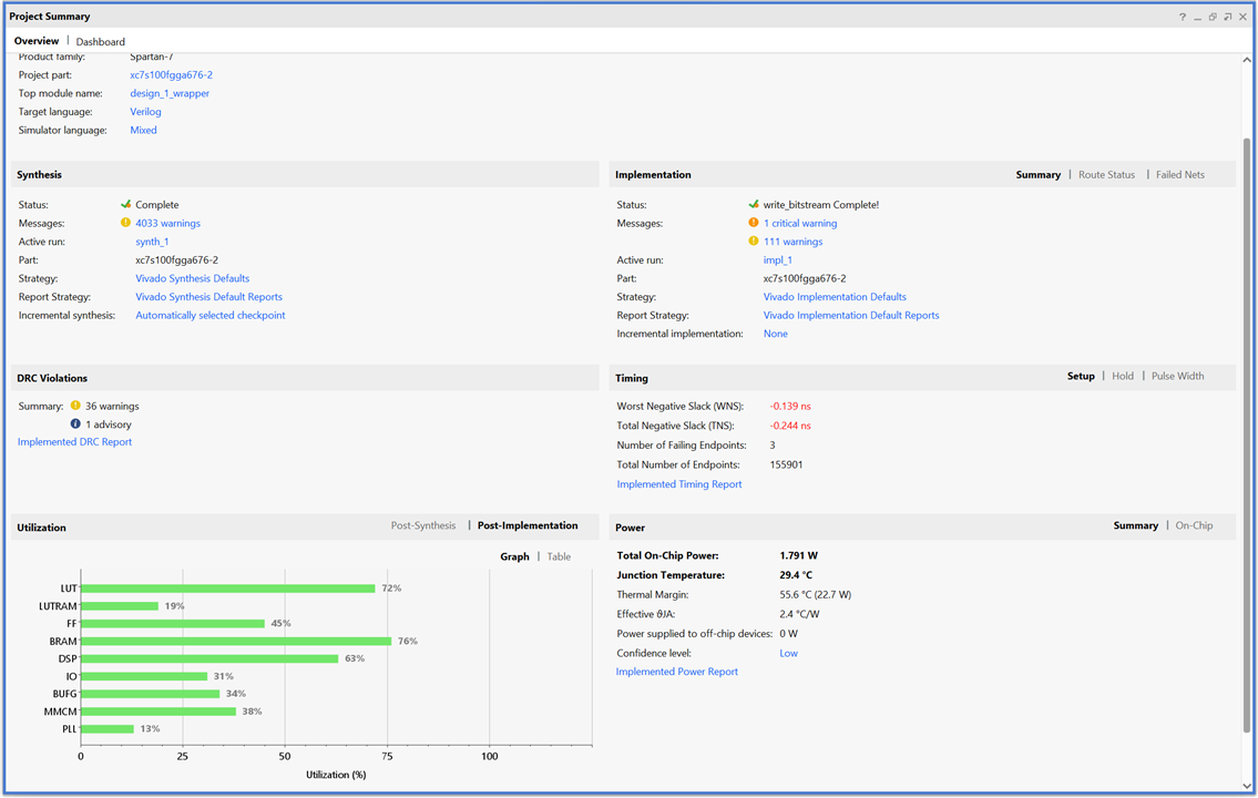
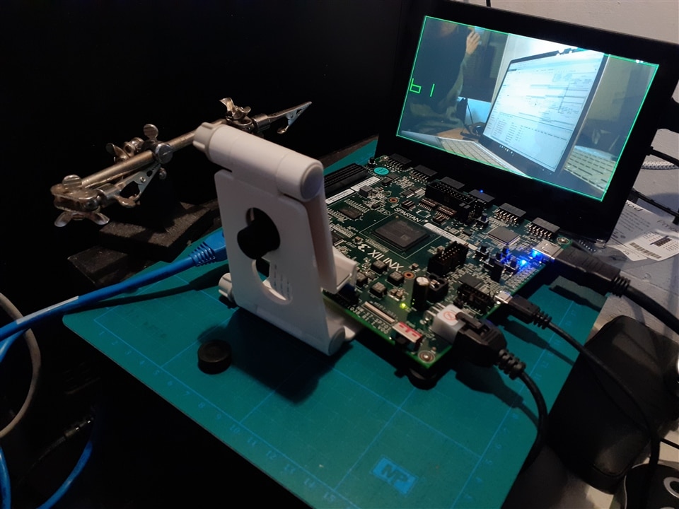
Finally program the FPGA:
Problems and next steps
Once I understood the operation and how to create the signals for the AXI Stream video I have started to create my own IP block to show the 16 digits of seven segments.
This is the output of the test bench. Looks good and the font is scalable as in the Adam Taylor font. I'm using BCD codification for the inputs. so with two int inputs I can set the 16 digits and can use 6 more symbols for each digit.
ss7_gen(dst_axi, 1080, 1920, 0x12345678, 0x90123456);

My design has a time violation of -0.11 ns compared to -0.64ns for Adam Taylor's design. But mine doesn't work at the moment.
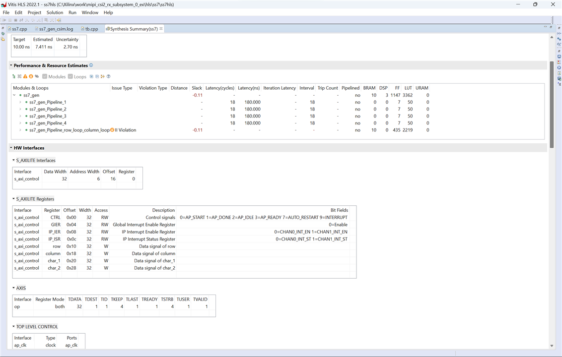
Unfortunately, my design doesn't output the AXI Stream correctly, so I added 3 ILA Integrated Logic Analyzer IP blocks for debugging.
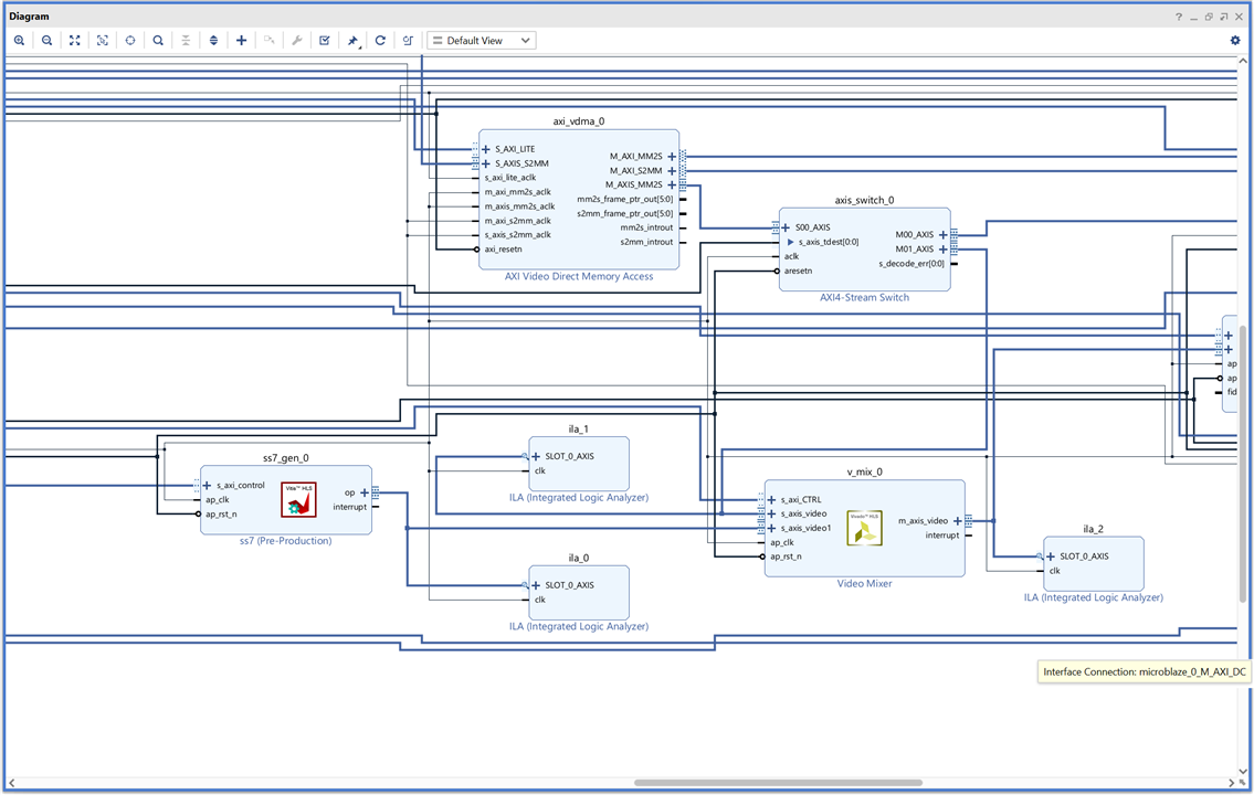
It's not all bad news. The logic analyzer works very well and it will help me to understand the AXI Stream interface much better.
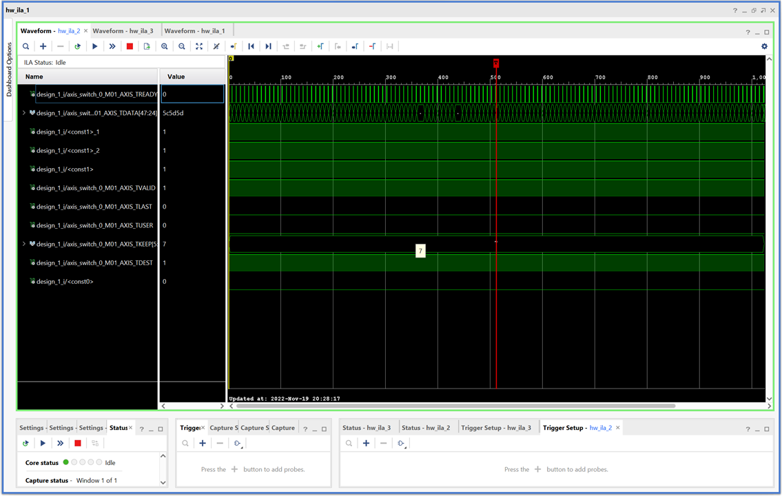
Now it's time to debug and redesign the block. I think I made a rookie mistake and started optimizing too soon and badly.
The Complete "Sensor Fusion for Firefighters" Blog Series
- Sensor Fusion for Firefighters. Introductory blog
- Sensor Fusion for Firefighters. Getting Started with the AMD Xilinx SP701
- Sensor Fusion for Firefighters. AMD Xilinx SP701 - MIPI Video Pipe Camera to HDMI Display
- Sensor Fusion for Firefighters. Displaying heads-up video on the live feed
- Sensor Fusion for Firefighters. Environmental monitor heads-up display on Xilinx Spartan-7 SP701 development board
- Sensor Fusion for Firefighters. Compass and Environmental HUD monitor with the Spartan-7
- Sensor Fusion for Firefighters. Thermal Vision, Compass and Environmental HUD monitor with the Spartan-7
- Sensor Fusion for Firefighters. Summary Blog
Top Comments