


In this post I describe my first contact with the AMD Xilinx SP701 evaluation board . I briefly review the contents of the evaluation kit. Then I connect the evaluation board for the first time and launch the execution of the built-in tests.
The kit includes a voucher with a Vivado Tools License and I explain the process followed to redeem the voucher.
I then perform the SP701 Software Install and Board Setup, testing the tests from a serial console.
Lastly, from Vivado I reviewed the design of the hardware that supports the evaluation tests of the SP701 development board and compiled the SP701 IPI Design.
To test the synthesized hardware I export the hardware platform and test it with the lwIP RAW Mode TCP Server Application sample from Vitis IDE.
Table of Contents
- Unboxing the Xilinx® Spartan®-7 SP701 Evaluation Kit
- Built-In Self-Test (BIST)
- Redeeming the Vivado Tools License Voucher
- SP701 Software Install and Board Setup
- SP701 IP Integrator Application
- Run the LwIP Ethernet Design
- Compile SP701 IPI Design
- Testing the lwIP RAW Mode TCP Server Application
- Related Links
- Conclusions
The Complete "Sensor Fusion for Firefighters" Blog Series
- Sensor Fusion for Firefighters. Introductory blog
- Sensor Fusion for Firefighters. Getting Started with the AMD Xilinx SP701
- Sensor Fusion for Firefighters. AMD Xilinx SP701 - MIPI Video Pipe Camera to HDMI Display
- Sensor Fusion for Firefighters. Displaying heads-up video on the live feed
- Sensor Fusion for Firefighters. Environmental monitor heads-up display on Xilinx Spartan-7 SP701 development board
- Sensor Fusion for Firefighters. Compass and Environmental HUD monitor with the Spartan-7
- Sensor Fusion for Firefighters. Thermal Vision, Compass and Environmental HUD monitor with the Spartan-7
- Sensor Fusion for Firefighters. Summary Blog
Unboxing the Xilinx® Spartan®-7 SP701 Evaluation Kit
The Xilinx® Spartan®-7 SP701 Evaluation Kit comes in a huge box. Similar to those toys where the most impressive thing is the size of the box. Only in this case the impressive thing is the versatility of the development board.

The SP701 Evaluation Kit contains:
- One SP701 Evaluation Board
- One Ethernet Cable
- One Micro USB Cable
- Three Power Cords
- One Power Adapter
- A printed copy of the SP701 Evaluation Kit Quick Start Guide with a Vivado Tools License Voucher.
SP701 Evaluation Board top view:

Featuring the Spartan-7 XC7S100 FPGA
- System Logic Cells 102,400
- Memory 1,100Kb DRAM, 4,320Kb Block RAM
- DSP Slices 160
- Maximum I/O Pins 400
- Additional Features 8 clock management tiles (1MMCM + 1 PLL)
- 1 analog to digital converter (XADC)
- 1 configuration AES / HMC Block
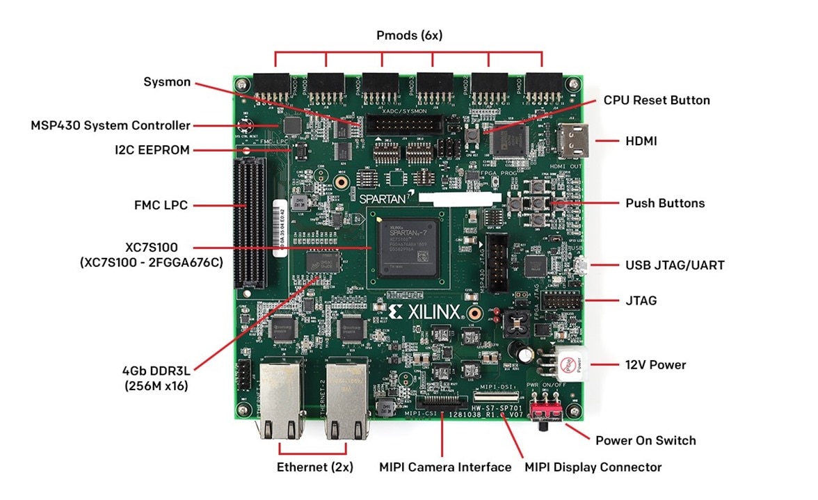
Interfaces of the SP701 Evaluation Board

The XC7S100 FPGA U1 implements bitstream encryption key technology. The SP701 board provides the encryption key backup battery. The Keystone 2998 battery retainer B1 is soldered to the board with the positive output connected to the FPGA U1 VCC_PSBATT pin D13. The B1 retainer accepts a 6.8 mm 1.5V single-cell, coin type battery similar to Seiko part number SR621SW, silver oxide, 1.55V non rechargeable battery.
SP701 Evaluation Board bottom view:

Built-In Self-Test (BIST)
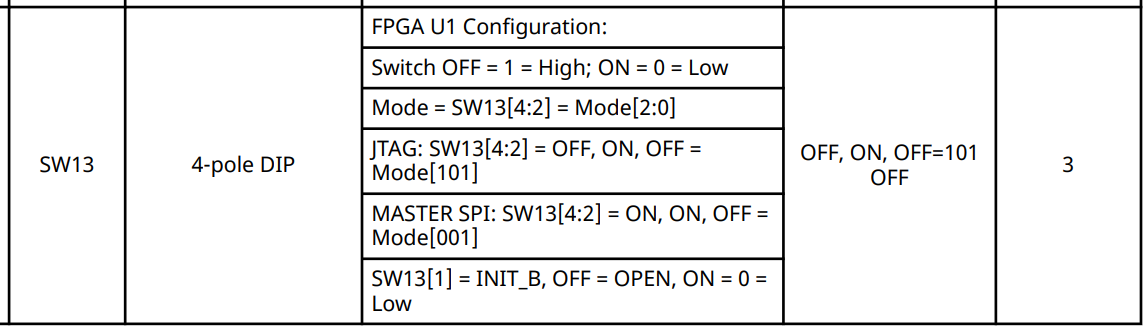
To run the Built-In Self-Test (BIST) you first have to put the FPGA into configuration mode by setting the SW13 DIP switches to down, up, up, down (1001). Down is OFF, which is equal to 1.
SW13 DIP switches:

See SP701 Evaluation Board User Guide (UG1319) • Documentation Portal (xilinx.com)
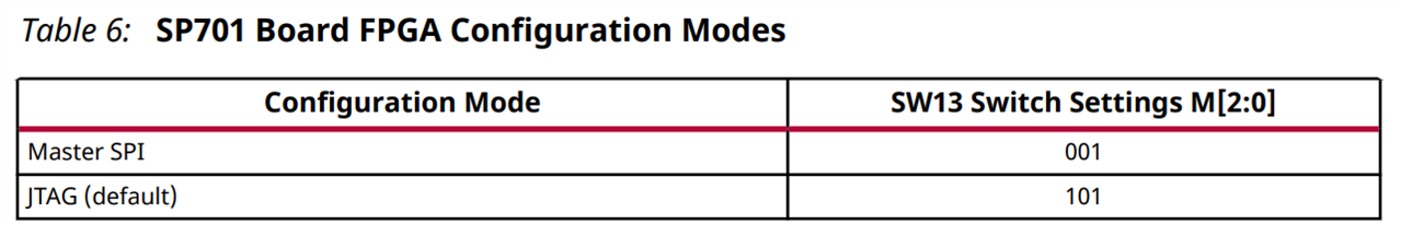
The SP701 board supports two of the 7 series FPGA configuration modes:
- Master SPI flash memory using the onboard QSPI flash memory
- JTAG
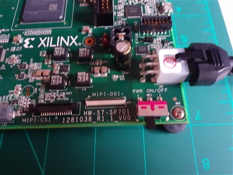
Then connect Power to the Board.
Connect the 6-pin power supply plug to J30, and power up the board using the SW11 switch.
AMD Xilinx SP701 Built-In Self-Test - First boot
The power on LED D14 for 12 V lets you know power is switched on and present.
When DONE LED DS1 glows blue, the Spartan-7 FPGA is configured successfully.
The BIST consists of a set of pass/fail tests. On power-up, the Clock, DDR3, BRAM, Serial Peripheral Interface (SPI) flash memory, I2C, and SYSMON tests run without user input.
A passing test is indicated when the corresponding GPIO LED for each test is ON.
The SYSMON test does not require user interaction.
The pushbutton (PB) tests require user interaction as described in the following section. The blinking LED indicates which test is waiting for user input.
In all my tests the first time the tests are run the I2C test fails. But if it is executed again by pressing the cpu reset SW8 or the PROG Switch SW1 the I2C test passes correctly.
Board Self-Test Assignments for GPIO LEDs
| D13 | D12 | D11 | D10 | D9 | D8 | D7 | D6 |
| Clock | DDR3 | BRAM | SPI | I2C | SYSMON | PB | All test done |
First run of the tests, the I2C test fails.
Second execution of the tests, the I2C test passes:
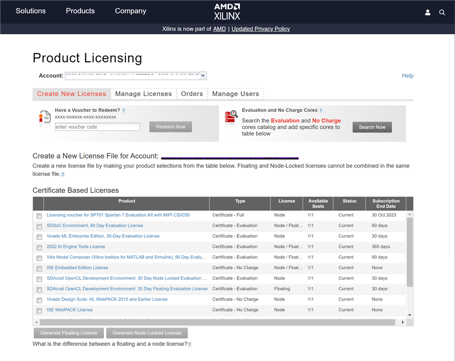
Redeeming the Vivado Tools License Voucher
The kit includes a voucher with a Vivado Tools License and I explain the process followed to redeem the voucher.

To redeem the Vivado Tools voucher code, go to www.xilinx.com/getlicense and enter the voucher code.
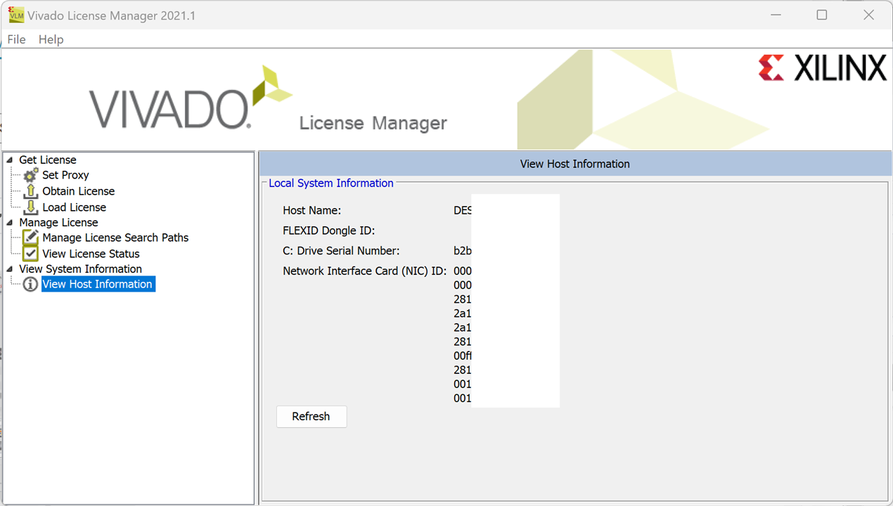
Generate node-locked license
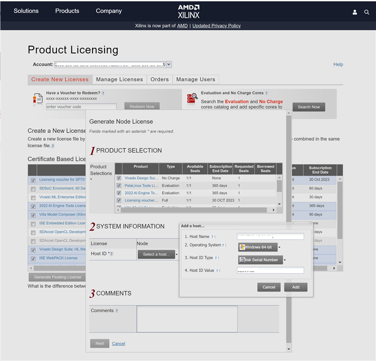
You can obtain this information from the Vivado License Manager if you already has installed the Vivado Design Suite.
Generate the License
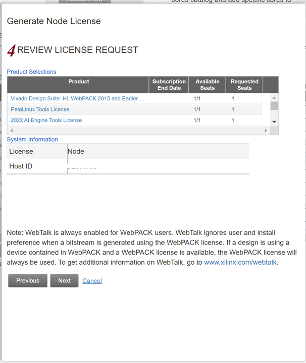
Accept the License Agreement
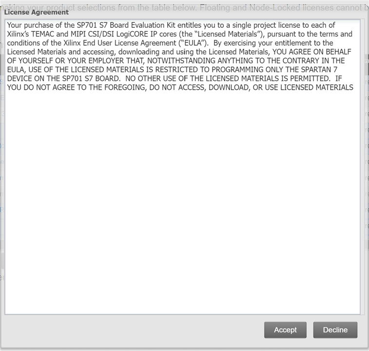
You can then generate the license file, which will be emailed to you.
Note: This voucher code can only be used once and must be redeemed within one year of purchase.
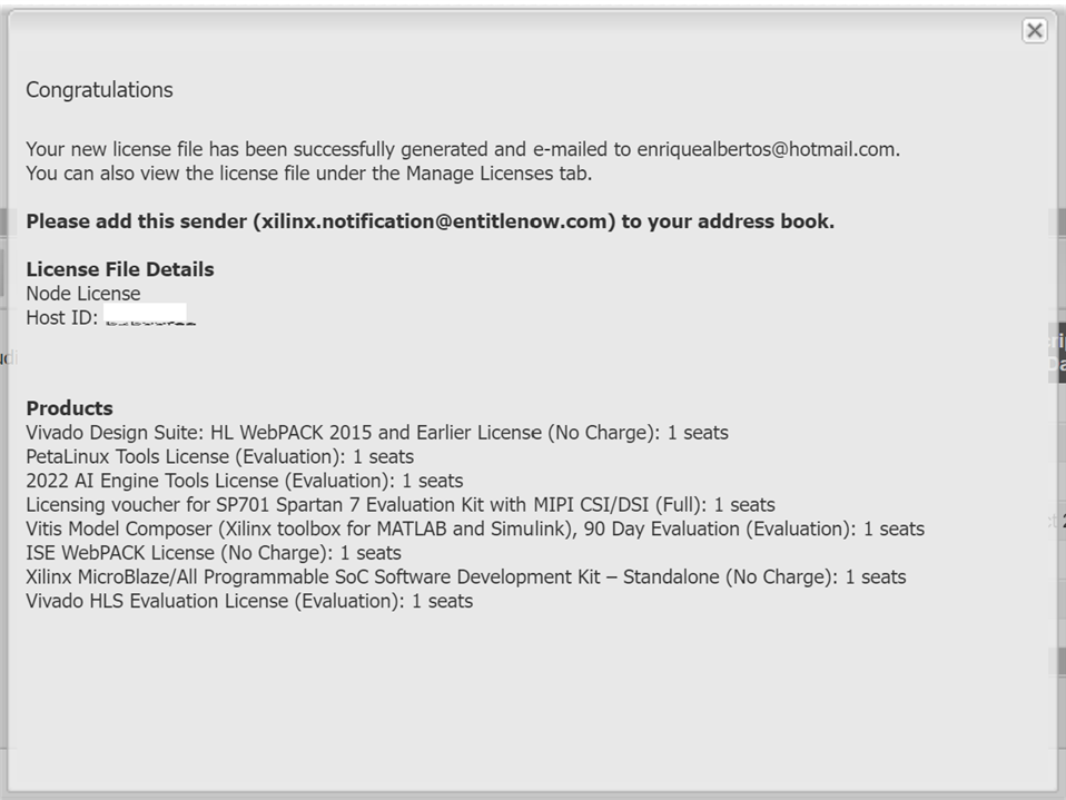
You will receive an email:
Dear %%:
Thank you for licensing your Xilinx� design tool or IP core product. This email includes the certificate license file to enable your product.

The license file can also be obtained by returning to the Xilinx Product Licensing Site:

http://www.xilinx.com/getlicense

For complete instructions on installing this license file, see the  Vivado Design Suite User Guide: Release Notes, Installation, and Licensing  document on the Xilinx web at:

http://www.xilinx.com/cgi-bin/docs/rdoc?v=latest;d=iil.pdf;a=ObtainManageLicense

Quick-Start License Installation Instructions

Node-locked Licenses:

These steps will copy your license file to the appropriate default directory (under %APPDATA%XilinxLicense for Windows and .Xilinx under $HOME for Linux).

1.     Save the attached license file (.lic) to your desktop or some other folder on your computer

2.     Run the Vivado License Manager

Windows:  Run ?Manage Xilinx Licenses? from underneath your Version group of the Xilinx Design Tools program group

Linux:  Type ?vlm? in a command-line window

3.     Select the ?Load License? screen and click on the ?Copy License?? button

4.     Browse to the downloaded license file and click ?Open?

Note:  IP licenses generated from the Xilinx Product Licensing Site are designed to be used with IP released against Vivado Design Suite (all versions) and 11.2 and later versions of ISE Design Suite IP.  If this is an IP license to be used with a 10.1 or earlier ISE Design Suite design tool installation, the license file should be copied to .XilinxCoregenCoreLicenses instead of %APPDATA%Xilinx for Windows or $HOME/.Xilinx for Linux.
Then you can use the Vivado License Manger to copy the license file to %APPDATA%XilinxLicense directory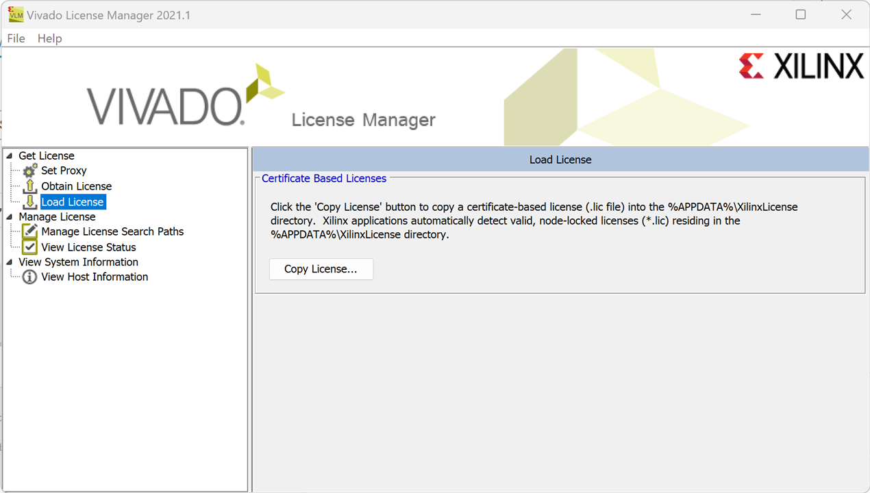
You can also review your licenses: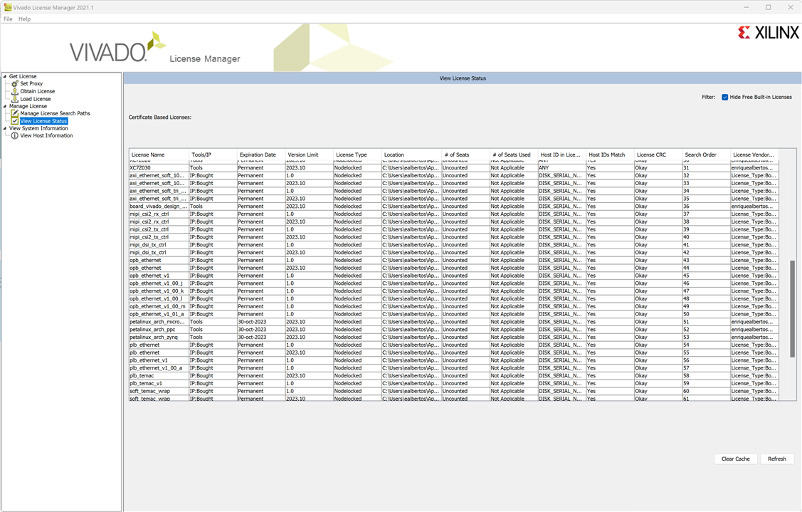
SP701 Software Install and Board Setup
Connections:

SP701 Hardware Setup
- Connect a USB Type-A to Micro-B cable to the USB UART connector (J5) on the SP701 board
- Connect this cable to your PC
- Connect the power supply to the SP701 (J30)
- Connect this power supply to a power outlet
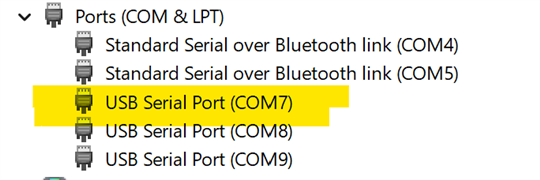
- Determine the COM Port numbers for your system
- Open the Device manager
- Control Panel → System → Device Manager
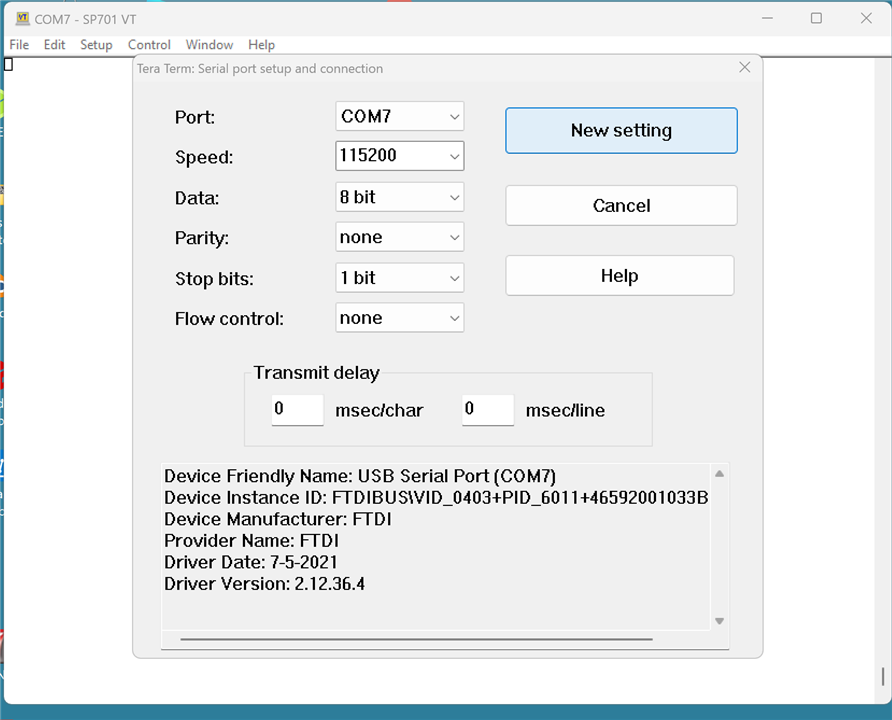
- Start a Terminal Program. I used Tera Term https://ttssh2.osdn.jp/ Tera Term Open Source Project (osdn.jp)
Ethernet Setup
I used a Startech.com DKT30CHVAUSP USB-C MULTIPORT ADAPTER, 4K, 100W as a second Ethernet adaptor
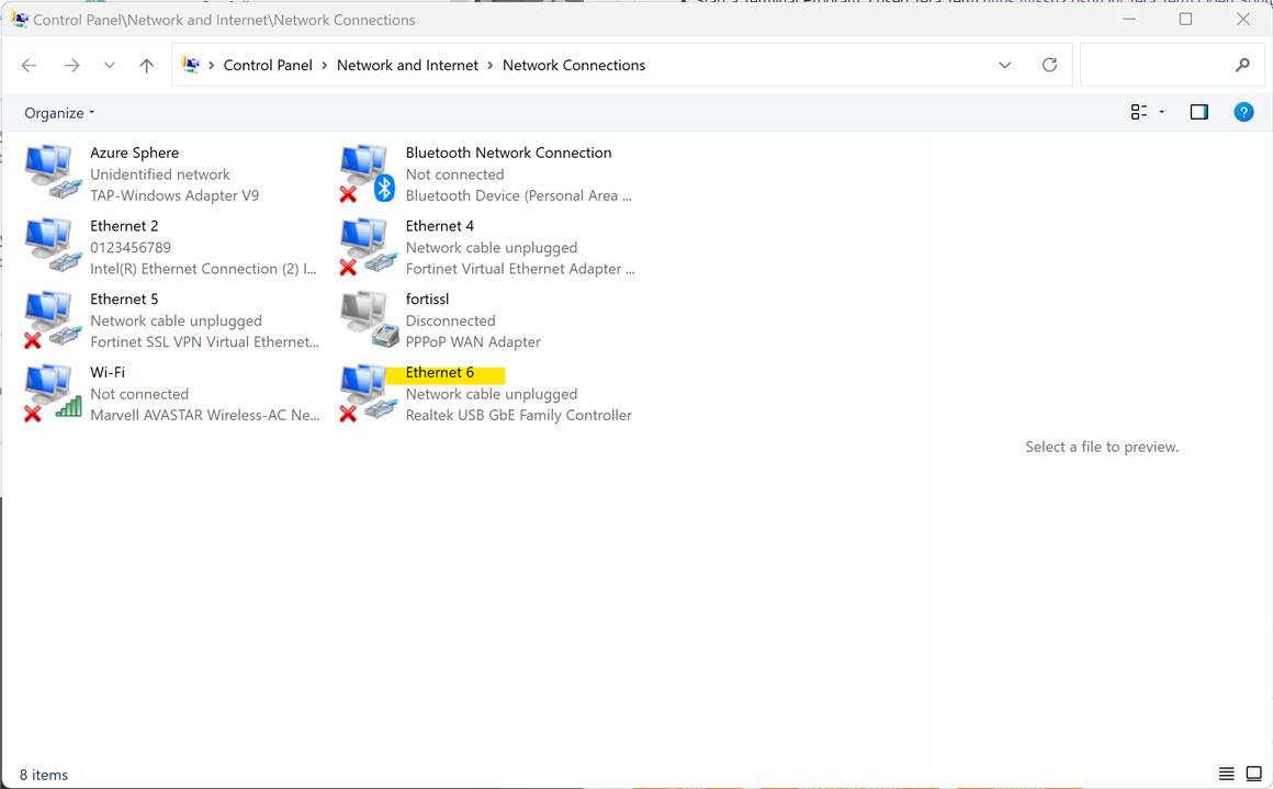
- Click on “Change adapter settings”
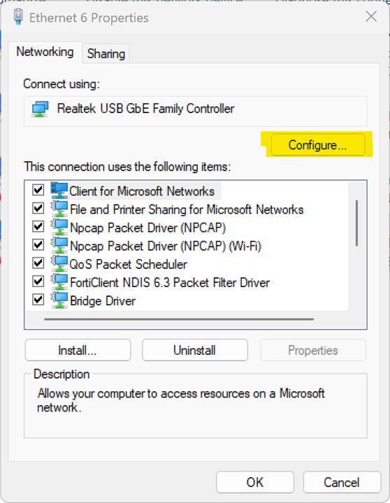
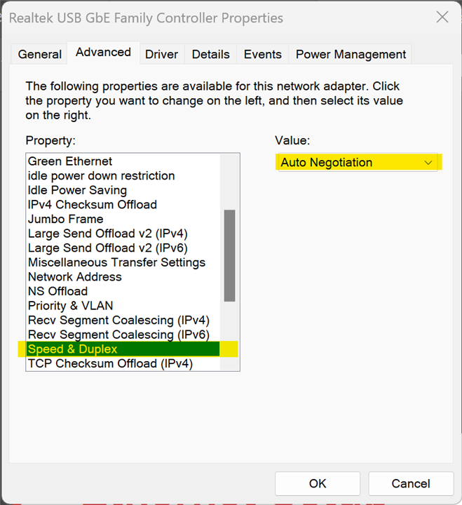
- Click Configure:
- Set the Link Speed & Duplex to Auto Negotiation then click OK
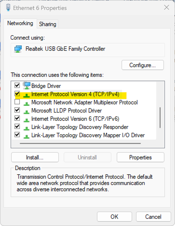
- Reopen the properties after the last step
- Double-click the Internet Protocol Version 4
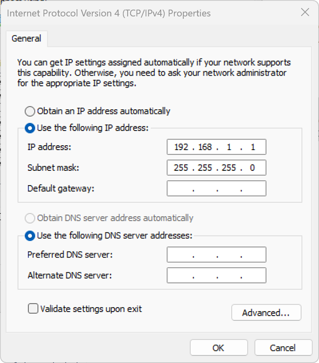
- Set your host (PC) to this IP Address: 192.168.1.1/24
Xilinx SP701 Evaluation Kit IPI Test
SP701 IP Integrator Application
The SP701 IP Integrator Application uses the following IPs
- Processor and Subsystems: MicroBlaze, MicroBlaze Debug Module (MDM), Processor System Reset, AXI Interrupt Controller, Concat, MicroBlaze Memory
- AXI Bus: AXI Interconnect, AXI Timer
- Memory: DDR3 SDRAM (MIG), AXI BRAM Controller, Block Memory Generator
- Peripherals: AXI Quad SPI, AXI IIC, AXI GPIO, AXI UART16550, System Management Wizard, Ethernet & DMA
- Other IP: Utility Buffer, freq_counter, diff_freq_counter, Clocking Wizard
Additional documentation, see:
- Vivado Design Suite Tcl Command Reference Guide (UG835)
- Designing IP Subsystems Using IP Integrator (UG994)
Downloading the blink bitstream
Unzip the RDF0503 - SP701 IPI Design Files (2018.3 C) ZIP file
- Download the blink bitstream
- In the Vivado Tcl Shell type:
cd C:/sp701_ipi/ready_for_download

source blink_download.tcl
****** Vivado v2021.1 (64-bit)
  **** SW Build 3247384 on Thu Jun 10 19:36:33 MDT 2021
  **** IP Build 3246043 on Fri Jun 11 00:30:35 MDT 2021
    ** Copyright 1986-2021 Xilinx, Inc. All Rights Reserved.

Vivado% cd c:/sp701_ipi
Vivado% dir
WARNING: [Common 17-259] Unknown Tcl command 'dir' sending command to the OS shell for execution. It is recommended to use 'exec' to send the command to the OS shell.
 Volume in drive C is Local Disk
 Volume Serial Number is B2B9-9FEA

 Directory of c:\sp701_ipi

01/11/2022  12:00    <DIR>          .
01/11/2022  12:00    <DIR>          data
01/11/2022  12:00    <DIR>          Packages
01/11/2022  12:00    <DIR>          ready_for_download
01/11/2022  12:00    <DIR>          sp701_ipi.cache
01/11/2022  12:00    <DIR>          sp701_ipi.hw
01/11/2022  12:00    <DIR>          sp701_ipi.ip_user_files
01/11/2022  12:00    <DIR>          sp701_ipi.runs
01/11/2022  12:00    <DIR>          sp701_ipi.sdk
01/11/2022  12:00    <DIR>          sp701_ipi.srcs
10/06/2019  23:48            83.579 sp701_ipi.xpr
10/06/2019  20:31            54.510 system.tcl
               2 File(s)        138.089 bytes
              10 Dir(s)  254.207.905.792 bytes free
Vivado% cd ready_for_download
Vivado% dir
WARNING: [Common 17-259] Unknown Tcl command 'dir' sending command to the OS shell for execution. It is recommended to use 'exec' to send the command to the OS shell.
 Volume in drive C is Local Disk
 Volume Serial Number is B2B9-9FEA

 Directory of c:\sp701_ipi\ready_for_download

01/11/2022  12:00    <DIR>          .
01/11/2022  12:00    <DIR>          ..
01/11/2022  12:00    <DIR>          .Xil
10/06/2019  23:46         2.766.641 blinkbist.bit
07/02/2019  00:10               378 blink_download.bat
05/06/2019  19:26               460 blink_download.tcl
10/06/2019  23:47         2.766.641 ipi_app.bit
07/02/2019  00:10               376 ipi_download.bat
10/06/2019  17:09               458 ipi_download.tcl
10/06/2019  20:11               503 lwip_download.bat
10/06/2019  17:58             1.359 lwip_download.tcl
10/06/2019  17:16         2.336.125 lwip_echo_server.bit
10/06/2019  17:52           335.052 lwip_echo_server.elf
07/02/2019  00:10               383 make_download_files.bat
10/06/2019  17:23             1.477 make_download_files.tcl
10/06/2019  23:36         2.354.645 system_wrapper.bit
10/06/2019  23:51               573 vivado.jou
10/06/2019  23:51             1.663 vivado.log
              15 File(s)     10.566.734 bytes
               3 Dir(s)  254.122.352.640 bytes free
Vivado% source blink_download.tcl
# open_hw
WARNING: 'open_hw' is deprecated, please use 'open_hw_manager' instead.
# connect_hw_server -url localhost:3121
INFO: [Labtools 27-2285] Connecting to hw_server url TCP:localhost:3121
INFO: [Labtools 27-2222] Launching hw_server...
INFO: [Labtools 27-2221] Launch Output:

****** Xilinx hw_server v2021.1
  **** Build date : Jun 10 2021 at 20:17:23
    ** Copyright 1986-2021 Xilinx, Inc. All Rights Reserved.


INFO: [Labtools 27-3415] Connecting to cs_server url TCP:localhost:3042
INFO: [Labtools 27-3417] Launching cs_server...
INFO: [Labtools 27-2221] Launch Output:


******** Xilinx cs_server v2021.1
  ****** Build date   : May 26 2021-19:32:33
    **** Build number : 2021.1.1622050353
      ** Copyright 2017-2022 Xilinx, Inc. All Rights Reserved.


connect_hw_server: Time (s): cpu = 00:00:00 ; elapsed = 00:00:10 . Memory (MB): peak = 1242.762 ; gain = 0.000
# current_hw_target [get_hw_targets */xilinx_tcf/*/*]
# set_property PARAM.FREQUENCY 10000000 [current_hw_target]
# open_hw_target
INFO: [Labtoolstcl 44-466] Opening hw_target localhost:3121/xilinx_tcf/Xilinx/46592001033A
# set_property PROGRAM.FILE {blinkbist.bit} [lindex [get_hw_devices] 0]
# current_hw_device [lindex [get_hw_devices] 0]
# refresh_hw_device -quiet [lindex [get_hw_devices] 0]
# program_hw_devices [lindex [get_hw_devices] 0]
INFO: [Labtools 27-3164] End of startup status: HIGH
# refresh_hw_device -quiet [lindex [get_hw_devices] 0]
# close_hw
WARNING: 'close_hw' is deprecated, please use 'close_hw_manager' instead.
****** Webtalk v2021.1 (64-bit)
  **** SW Build 3247384 on Thu Jun 10 19:36:33 MDT 2021
  **** IP Build 3246043 on Fri Jun 11 00:30:35 MDT 2021
    ** Copyright 1986-2021 Xilinx, Inc. All Rights Reserved.

source c:/sp701_ipi/ready_for_download/.Xil/Vivado-4496-DESKTOP-KD82ADA/webtalk/labtool_webtalk.tcl -notrace
INFO: [Common 17-186] 'c:/sp701_ipi/ready_for_download/.Xil/Vivado-4496-DESKTOP-KD82ADA/webtalk/usage_statistics_ext_labtool.xml' has been successfully sent to Xilinx on Tue Nov  1 12:07:38 2022. For additional details about this file, please refer to the WebTalk help file at C:/Xilinx/Vivado/2021.1/doc/webtalk_introduction.html.
webtalk_transmit: Time (s): cpu = 00:00:00 ; elapsed = 00:00:06 . Memory (MB): peak = 86.410 ; gain = 4.520
INFO: [Common 17-206] Exiting Webtalk at Tue Nov  1 12:07:38 2022...
close_hw_manager: Time (s): cpu = 00:00:00 ; elapsed = 00:00:09 . Memory (MB): peak = 2261.645 ; gain = 11.527
Vivado%
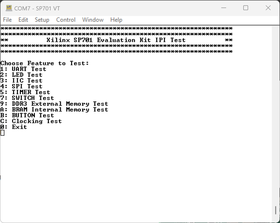
SP701 IP Integrator application serial console output
************************************************************
************************************************************
**          Xilinx SP701 Evaluation Kit IPI Test          **
************************************************************
************************************************************

Choose Feature to Test:
1: UART Test
2: LED Test
3: IIC Test
4: SPI Test
5: TIMER Test
7: SWITCH Test
9: DDR3 External Memory Test
A: BRAM Internal Memory Test
B: BUTTON Test
C: Clocking Test
0: Exit


************************************************************
************************************************************
**          Xilinx SP701 Evaluation Kit IPI Test          **
************************************************************
************************************************************

Choose Feature to Test:
1: UART Test
2: LED Test
3: IIC Test
4: SPI Test
5: TIMER Test
7: SWITCH Test
9: DDR3 External Memory Test
A: BRAM Internal Memory Test
B: BUTTON Test
C: Clocking Test
0: Exit

Press any key to return to main menu
Choose Feature to Test:
1: UART Test
2: LED Test
3: IIC Test
4: SPI Test
5: TIMER Test
7: SWITCH Test
9: DDR3 External Memory Test
A: BRAM Internal Memory Test
B: BUTTON Test
C: Clocking Test
0: Exit
1

********************************************************
********************************************************
**                  SP701 - UART Test                 **
********************************************************
********************************************************
Testing UART
115200,8,N,1
Hello world!
UART Test Passed

Press any key to return to main menu
Choose Feature to Test:
1: UART Test
2: LED Test
3: IIC Test
4: SPI Test
5: TIMER Test
7: SWITCH Test
9: DDR3 External Memory Test
A: BRAM Internal Memory Test
B: BUTTON Test
C: Clocking Test
0: Exit
2

********************************************************
********************************************************
**                SP701 - GPIO LED Test               **
********************************************************
********************************************************
Watch the LEDs
Press any key to return to main menu
Choose Feature to Test:
1: UART Test
2: LED Test
3: IIC Test
4: SPI Test
5: TIMER Test
7: SWITCH Test
9: DDR3 External Memory Test
A: BRAM Internal Memory Test
B: BUTTON Test
C: Clocking Test
0: Exit
4

********************************************************
********************************************************
**                  SP701 - SPI Test                  **
********************************************************
********************************************************
Successfully ran Spi selftest Example
Press any key to return to main menu
Choose Feature to Test:
1: UART Test
2: LED Test
3: IIC Test
4: SPI Test
5: TIMER Test
7: SWITCH Test
9: DDR3 External Memory Test
A: BRAM Internal Memory Test
B: BUTTON Test
C: Clocking Test
0: Exit
5

********************************************************
********************************************************
**                 SP701 - Timer Test                 **
********************************************************
********************************************************
Starting IPI Timer Example
Setting up the timer counter and interrupt subsystem
XTmrCtr_SetResetValue to 0xFFFFF000
Starting the timer counter
Timer counter has expired
XTmrCtr_DisableIntr success
Completed IPI Timer Example!
Press any key to return to main menu
Choose Feature to Test:
1: UART Test
2: LED Test
3: IIC Test
4: SPI Test
5: TIMER Test
7: SWITCH Test
9: DDR3 External Memory Test
A: BRAM Internal Memory Test
B: BUTTON Test
C: Clocking Test
0: Exit
7

********************************************************
********************************************************
**              SP701 - GPIO Switch Test              **
********************************************************
********************************************************
Data read from GPIO Input is 0x0
Press any key to return to main menu
Choose Feature to Test:
1: UART Test
2: LED Test
3: IIC Test
4: SPI Test
5: TIMER Test
7: SWITCH Test
9: DDR3 External Memory Test
A: BRAM Internal Memory Test
B: BUTTON Test
C: Clocking Test
0: Exit
9

********************************************************
********************************************************
**                  SP701 - DDR3 TEST                 **
********************************************************
********************************************************

MIG Memory Test
Testing address range 0x80000000-0x80100000.
Iteration 1 of 1
Pass A) ICache:  On, DCache:  On
        TEST0: Write all memory to 0x00000000 and check
                Writing...
                Reading...
        Test Complete Status = SUCCESS
        TEST1: Write all memory to 0xFFFFFFFF and check
                Writing...
                Reading...
        Test Complete Status = SUCCESS

        TEST2: Testing for stuck together bank/row/col bits
                Clearing memory to zeros...
                Writing and Reading...
        Test Complete Status = SUCCESS

        TEST3: Testing for maximum ba/row/col noise
                This test performs 16 word writes followed by 16 word reads
                Each 64 bytes inverts the ba/row/col address
                Initializing Memory to 0xA5A5A5A5...
                Writing and Reading...
        Test Complete Status = SUCCESS
        TEST4: Testing for Inverse Data at Address
                Writing...
                Reading...
        Test Complete Status = SUCCESS

                Number of errors in this pass = 0

Pass B) ICache: Off, DCache: Off
        TEST0: Write all memory to 0x00000000 and check
                Writing...
                Reading...
        Test Complete Status = SUCCESS
        TEST1: Write all memory to 0xFFFFFFFF and check
                Writing...
                Reading...
        Test Complete Status = SUCCESS

        TEST2: Testing for stuck together bank/row/col bits
                Clearing memory to zeros...
                Writing and Reading...
        Test Complete Status = SUCCESS

        TEST3: Testing for maximum ba/row/col noise
                This test performs 16 word writes followed by 16 word reads
                Each 64 bytes inverts the ba/row/col address
                Initializing Memory to 0xA5A5A5A5...
                Writing and Reading...
        Test Complete Status = SUCCESS
        TEST4: Testing for Inverse Data at Address
                Writing...
                Reading...
        Test Complete Status = SUCCESS

                Number of errors in this pass = 0

MIG Memory Test iteration #1 has PASSED!
Total number of errors for all iterations = 0
### DDR3 Memory Test finished successfully ###
Press any key to return to main menu
Choose Feature to Test:
1: UART Test
2: LED Test
3: IIC Test
4: SPI Test
5: TIMER Test
7: SWITCH Test
9: DDR3 External Memory Test
A: BRAM Internal Memory Test
B: BUTTON Test
C: Clocking Test
0: Exit
A

********************************************************
********************************************************
**                SP701 - AXI BRAM TEST               **
********************************************************
********************************************************

AXI BRAM Memory Test
Testing address range 0xC0000000-0xC001FFFF.
Iteration 1 of 1
Pass A) ICache:  On, DCache:  On
        TEST0: Write all memory to 0x00000000 and check
                Writing...
                Reading...
        Test Complete Status = SUCCESS
        TEST1: Write all memory to 0xFFFFFFFF and check
                Writing...
                Reading...
        Test Complete Status = SUCCESS

        TEST2: Testing for stuck together bank/row/col bits
                Clearing memory to zeros...
                Writing and Reading...
        Test Complete Status = SUCCESS

        TEST4: Testing for Inverse Data at Address
                Writing...
                Reading...
        Test Complete Status = SUCCESS

                Number of errors in this pass = 0

Pass B) ICache: Off, DCache: Off
        TEST0: Write all memory to 0x00000000 and check
                Writing...
                Reading...
        Test Complete Status = SUCCESS
        TEST1: Write all memory to 0xFFFFFFFF and check
                Writing...
                Reading...
        Test Complete Status = SUCCESS

        TEST2: Testing for stuck together bank/row/col bits
                Clearing memory to zeros...
                Writing and Reading...
        Test Complete Status = SUCCESS

        TEST4: Testing for Inverse Data at Address
                Writing...
                Reading...
        Test Complete Status = SUCCESS

                Number of errors in this pass = 0

AXI BRAM test iteration #1 has PASSED!
Total number of errors for all iterations = 0
### Program finished successfully ###
Press any key to return to main menu
Choose Feature to Test:
1: UART Test
2: LED Test
3: IIC Test
4: SPI Test
5: TIMER Test
7: SWITCH Test
9: DDR3 External Memory Test
A: BRAM Internal Memory Test
B: BUTTON Test
C: Clocking Test
0: Exit
B

********************************************************
********************************************************
**                 SP701 - Button Test                **
********************************************************
********************************************************
Press west button

Press south button

Press east button

Press north button

Press center button

Press any button

Successfully ran GPIO Pushbutton Test
Press any key to return to main menu
Choose Feature to Test:
1: UART Test
2: LED Test
3: IIC Test
4: SPI Test
5: TIMER Test
7: SWITCH Test
9: DDR3 External Memory Test
A: BRAM Internal Memory Test
B: BUTTON Test
C: Clocking Test
0: Exit
C

********************************************************
********************************************************
**              SP701 - Clock Frequencies             **
********************************************************
********************************************************

FMC_CLK0_M2C          failed
FMC_CLK1_M2C          failed
FMC_CLK0_M2C           =    0.000
FMC_CLK1_M2C           =    8.498
MIG_ADDN_UI_CLK        =  100.000

2 Clocks Failed

Clocking Test Failed

Press any key to return to main menu
Choose Feature to Test:
1: UART Test
2: LED Test
3: IIC Test
4: SPI Test
5: TIMER Test
7: SWITCH Test
9: DDR3 External Memory Test
A: BRAM Internal Memory Test
B: BUTTON Test
C: Clocking Test
0: Exit

Press any key to return to main menu
The IIC Test expects a Whizz FMC XM107 board to be installed to the FMC LPC connector (J21) Available through Whizz Systems
I don't have that card so the the test fails.
************************************************************
************************************************************
**          Xilinx SP701 Evaluation Kit IPI Test          **
************************************************************
************************************************************

Choose Feature to Test:
1: UART Test
2: LED Test
3: IIC Test
4: SPI Test
5: TIMER Test
7: SWITCH Test
9: DDR3 External Memory Test
A: BRAM Internal Memory Test
B: BUTTON Test
C: Clocking Test
0: Exit
3

*************************************************************
** SP701 EEPROM IIC Test
*************************************************************
Calling iic_read

Reading EEPROM data from EEPROM

ReadBuffer[00] = 0xFF
ReadBuffer[01] = 0xFF
ReadBuffer[02] = 0xFF
ReadBuffer[03] = 0xFF
ReadBuffer[04] = 0xFF
ReadBuffer[05] = 0xFF
ReadBuffer[06] = 0xFF
ReadBuffer[07] = 0xFF
ReadBuffer[08] = 0xFF
ReadBuffer[09] = 0xFF
ReadBuffer[10] = 0xFF
ReadBuffer[11] = 0xFF
ReadBuffer[12] = 0xFF
ReadBuffer[13] = 0xFF
ReadBuffer[14] = 0xFF
ReadBuffer[15] = 0xFF


SP701 EEPROM IIC EEPROM Test PASSED

*************************************************************
** SP701 Si570 IIC Test
*************************************************************
Calling iic_read

Reading EEPROM data from Si570

ReadBuffer[00] = 0x60
ReadBuffer[01] = 0xC3
ReadBuffer[02] = 0x10
ReadBuffer[03] = 0x9B
ReadBuffer[04] = 0x8A
ReadBuffer[05] = 0x44
ReadBuffer[06] = 0x07
ReadBuffer[07] = 0xC2
ReadBuffer[08] = 0xC0
ReadBuffer[09] = 0x00
ReadBuffer[10] = 0x00
ReadBuffer[11] = 0x00
ReadBuffer[12] = 0x07
ReadBuffer[13] = 0xC2
ReadBuffer[14] = 0xC0
ReadBuffer[15] = 0x00


SP701 Si570 IIC EEPROM Test PASSED

*************************************************************
** SP701 INA226 U32 IIC Test
*************************************************************
Calling iic_read

Reading EEPROM data from INA226 U32

ReadBuffer[00] = 0x41
ReadBuffer[01] = 0x01
ReadBuffer[02] = 0x26
ReadBuffer[03] = 0x00
ReadBuffer[04] = 0x00
ReadBuffer[05] = 0x00
ReadBuffer[06] = 0x00
ReadBuffer[07] = 0x00
ReadBuffer[08] = 0xFF
ReadBuffer[09] = 0xFF
ReadBuffer[10] = 0x80
ReadBuffer[11] = 0xF3
ReadBuffer[12] = 0xFF
ReadBuffer[13] = 0xFF
ReadBuffer[14] = 0x54
ReadBuffer[15] = 0x22


SP701 INA226 U32 IIC EEPROM Test PASSED

*************************************************************
** SP701 INA226 U33 IIC Test
*************************************************************
Calling iic_read

Reading EEPROM data from INA226 U33

ReadBuffer[00] = 0x41
ReadBuffer[01] = 0x03
ReadBuffer[02] = 0x03
ReadBuffer[03] = 0x00
ReadBuffer[04] = 0x00
ReadBuffer[05] = 0x00
ReadBuffer[06] = 0x00
ReadBuffer[07] = 0x00
ReadBuffer[08] = 0xFF
ReadBuffer[09] = 0xFF
ReadBuffer[10] = 0x80
ReadBuffer[11] = 0xFB
ReadBuffer[12] = 0xFF
ReadBuffer[13] = 0xFF
ReadBuffer[14] = 0x54
ReadBuffer[15] = 0x22


SP701 INA226 U33 IIC EEPROM Test PASSED

*************************************************************
** SP701 MP5470 IIC Test
*************************************************************
Calling iic_read

Reading EEPROM data from MP5470

ReadBuffer[00] = 0x03
ReadBuffer[01] = 0xE9
ReadBuffer[02] = 0x2D
ReadBuffer[03] = 0x22
ReadBuffer[04] = 0xEB
ReadBuffer[05] = 0x7D
ReadBuffer[06] = 0x33
ReadBuffer[07] = 0x5D
ReadBuffer[08] = 0x9D
ReadBuffer[09] = 0x33
ReadBuffer[10] = 0x5F
ReadBuffer[11] = 0xB7
ReadBuffer[12] = 0xF4
ReadBuffer[13] = 0x68
ReadBuffer[14] = 0x40
ReadBuffer[15] = 0x01


SP701 MP5470 IIC EEPROM Test PASSED

*************************************************************
** SP701 FMC IIC Test
*************************************************************
Calling iic_read

Reading EEPROM data from FMC
The clock test also requires an XM107 board
Choose Feature to Test:
1: UART Test
2: LED Test
3: IIC Test
4: SPI Test
5: TIMER Test
7: SWITCH Test
9: DDR3 External Memory Test
A: BRAM Internal Memory Test
B: BUTTON Test
C: Clocking Test
0: Exit
C

********************************************************
********************************************************
**              SP701 - Clock Frequencies             **
********************************************************
********************************************************

FMC_CLK0_M2C          failed
FMC_CLK1_M2C          failed
FMC_CLK0_M2C           =    0.000
FMC_CLK1_M2C           =    0.879
MIG_ADDN_UI_CLK        =  100.000

2 Clocks Failed

Clocking Test Failed
Run the LwIP Ethernet Design
- Download the LwIP bitstream and ELF file
- In the Vivado Tcl Shell type:
exec xsdb lwip_download.tcl
Vivado% exec xsdb lwip_download.tcl
file copy -force ../sp701_ipi.sdk/lwip_echo_server/Debug/lwip_echo_server.elf .
file copy -force ../sp701_ipi.sdk/system_wrapper_hw_platform_0/system_wrapper.bit .
disconnect
connect -url tcp:127.0.0.1:3121
attempting to launch hw_server

****** Xilinx hw_server v2021.1
  **** Build date : Jun 10 2021 at 20:17:23
    ** Copyright 1986-2021 Xilinx, Inc. All Rights Reserved.

INFO: hw_server application started
INFO: Use Ctrl-C to exit hw_server application


****** Xilinx hw_server v2021.1

  **** Build date : Jun 10 2021 at 20:17:23

    ** Copyright 1986-2021 Xilinx, Inc. All Rights Reserved.


INFO: hw_server application started

INFO: Use Ctrl-C to exit hw_server application


INFO: To connect to this hw_server instance use url: TCP:127.0.0.1:3121


tcfchan#0
jtag target 1
jtag frequency 5000000
5000000
targets -set -filter {name =~"*xc7s100*"}
rst -srst
fpga -file {system_wrapper.bit}
targets -set -filter {name =~"*MicroBlaze*0"}
rst -processorWARNING: If the reset is being triggered after powering on the device,

         write bootloop at reset vector address (0xffff0000), or use

         -clear-registers option, to avoid unpredictable behavior.

         Further warnings will be suppressed

dow {lwip_echo_server.elf}
targets -set -filter {name =~"*MicroBlaze*0"}
con
disconnect
exit
Vivado%
PC console
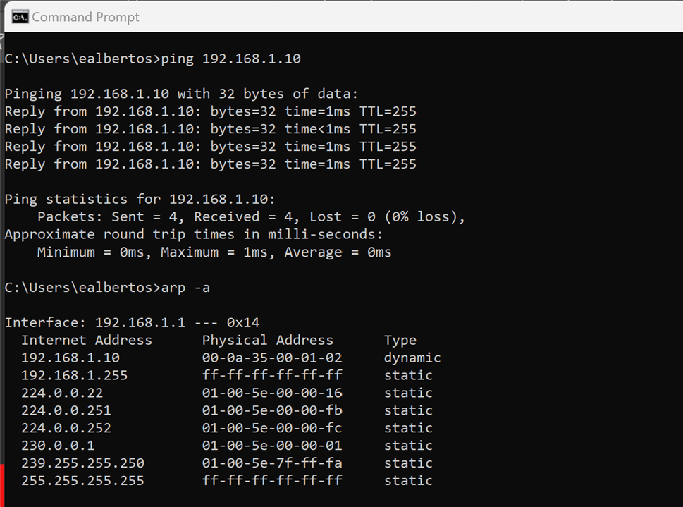
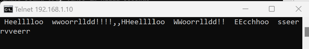
Testing the echo server
telnet 192.168.1.10 8
Compile SP701 IPI Design
- Open the SP701 Design:
- <DesigThe design is fully implemented; you can recompile, or export to SDK
- To recompile, right-click synth_1, select Reset Runs then Generate Bitstreamn Name>\sp701_ipi\sp701_ipi.xpr
- The IPI Design has been implemented with IP Integrator (IPI)
- Click Open Block Design
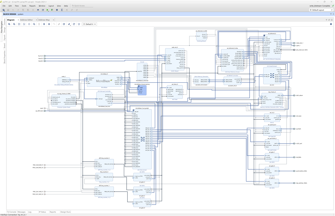
- All the IP Blocks used in the design can be seen in this view
- Click Open Implemented Design
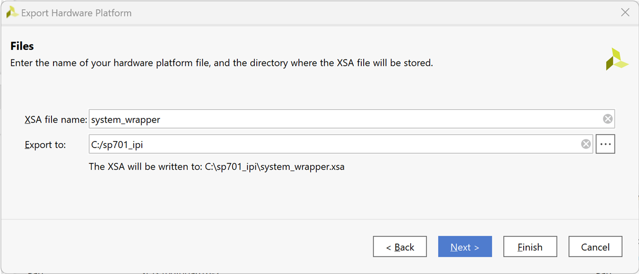
Export Hardware Platform
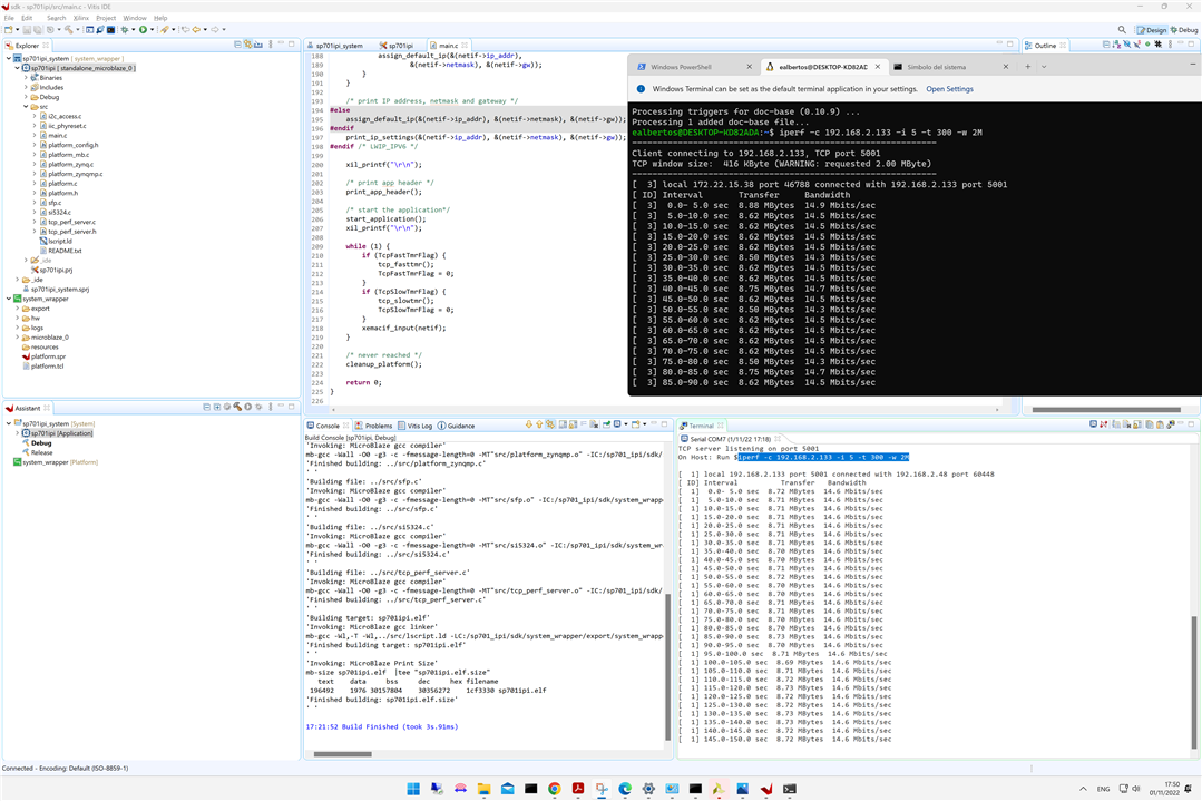
Testing the lwIP RAW Mode TCP Server Application
- SDK Software Compile - Build ELF files in SDK
main.c source code
/*
* Copyright (C) 2018 - 2019 Xilinx, Inc.
* All rights reserved.
*
* Redistribution and use in source and binary forms, with or without modification,
* are permitted provided that the following conditions are met:
*
* 1. Redistributions of source code must retain the above copyright notice,
* this list of conditions and the following disclaimer.
* 2. Redistributions in binary form must reproduce the above copyright notice,
* this list of conditions and the following disclaimer in the documentation
* and/or other materials provided with the distribution.
* 3. The name of the author may not be used to endorse or promote products
* derived from this software without specific prior written permission.
*
* THIS SOFTWARE IS PROVIDED BY THE AUTHOR ``AS IS'' AND ANY EXPRESS OR IMPLIED
* WARRANTIES, INCLUDING, BUT NOT LIMITED TO, THE IMPLIED WARRANTIES OF
* MERCHANTABILITY AND FITNESS FOR A PARTICULAR PURPOSE ARE DISCLAIMED. IN NO EVENT
* SHALL THE AUTHOR BE LIABLE FOR ANY DIRECT, INDIRECT, INCIDENTAL, SPECIAL,
* EXEMPLARY, OR CONSEQUENTIAL DAMAGES (INCLUDING, BUT NOT LIMITED TO, PROCUREMENT
* OF SUBSTITUTE GOODS OR SERVICES; LOSS OF USE, DATA, OR PROFITS; OR BUSINESS
* INTERRUPTION) HOWEVER CAUSED AND ON ANY THEORY OF LIABILITY, WHETHER IN
* CONTRACT, STRICT LIABILITY, OR TORT (INCLUDING NEGLIGENCE OR OTHERWISE) ARISING
* IN ANY WAY OUT OF THE USE OF THIS SOFTWARE, EVEN IF ADVISED OF THE POSSIBILITY
* OF SUCH DAMAGE.
*
*/
#include <stdio.h>
#include "xparameters.h"
#include "netif/xadapter.h"
#include "platform.h"
#include "platform_config.h"
#include "lwipopts.h"
#include "xil_printf.h"
#include "sleep.h"
#include "lwip/priv/tcp_priv.h"
#include "lwip/init.h"
#include "lwip/inet.h"
#if LWIP_IPV6==1
#include "lwip/ip6_addr.h"
#include "lwip/ip6.h"
#else
#if LWIP_DHCP==1
#include "lwip/dhcp.h"
extern volatile int dhcp_timoutcntr;
#endif
#define DEFAULT_IP_ADDRESS "192.168.1.10"
#define DEFAULT_IP_MASK "255.255.255.0"
#define DEFAULT_GW_ADDRESS "192.168.1.1"
#endif /* LWIP_IPV6 */
extern volatile int TcpFastTmrFlag;
extern volatile int TcpSlowTmrFlag;
void platform_enable_interrupts(void);
void start_application(void);
void print_app_header(void);
#if defined (__arm__) && !defined (ARMR5)
#if XPAR_GIGE_PCS_PMA_SGMII_CORE_PRESENT == 1 || \
XPAR_GIGE_PCS_PMA_1000BASEX_CORE_PRESENT == 1
int ProgramSi5324(void);
int ProgramSfpPhy(void);
#endif
#endif
#ifdef XPS_BOARD_ZCU102
#ifdef XPAR_XIICPS_0_DEVICE_ID
int IicPhyReset(void);
#endif
#endif
struct netif server_netif;
#if LWIP_IPV6==1
static void print_ipv6(char *msg, ip_addr_t *ip)
{
print(msg);
xil_printf(" %s\n\r", inet6_ntoa(*ip));
}
#else
static void print_ip(char *msg, ip_addr_t *ip)
{
print(msg);
xil_printf("%d.%d.%d.%d\r\n", ip4_addr1(ip), ip4_addr2(ip),
ip4_addr3(ip), ip4_addr4(ip));
}
static void print_ip_settings(ip_addr_t *ip, ip_addr_t *mask, ip_addr_t *gw)
{
print_ip("Board IP: ", ip);
print_ip("Netmask : ", mask);
print_ip("Gateway : ", gw);
}
static void assign_default_ip(ip_addr_t *ip, ip_addr_t *mask, ip_addr_t *gw)
{
int err;
xil_printf("Configuring default IP %s \r\n", DEFAULT_IP_ADDRESS);
err = inet_aton(DEFAULT_IP_ADDRESS, ip);
if (!err)
xil_printf("Invalid default IP address: %d\r\n", err);
err = inet_aton(DEFAULT_IP_MASK, mask);
if (!err)
xil_printf("Invalid default IP MASK: %d\r\n", err);
err = inet_aton(DEFAULT_GW_ADDRESS, gw);
if (!err)
xil_printf("Invalid default gateway address: %d\r\n", err);
}
#endif /* LWIP_IPV6 */
int main(void)
{
struct netif *netif;
/* the mac address of the board. this should be unique per board */
unsigned char mac_ethernet_address[] = {
0x00, 0x0a, 0x35, 0x00, 0x01, 0x02 };
netif = &server_netif;
#if defined (__arm__) && !defined (ARMR5)
#if XPAR_GIGE_PCS_PMA_SGMII_CORE_PRESENT == 1 || \
XPAR_GIGE_PCS_PMA_1000BASEX_CORE_PRESENT == 1
ProgramSi5324();
ProgramSfpPhy();
#endif
#endif
/* Define this board specific macro in order perform PHY reset
* on ZCU102
*/
#ifdef XPS_BOARD_ZCU102
IicPhyReset();
#endif
init_platform();
xil_printf("\r\n\r\n");
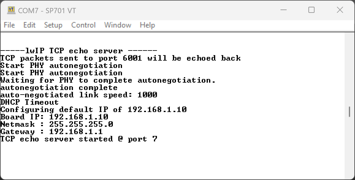
xil_printf("-----lwIP RAW Mode TCP Server Application-----\r\n");
/* initialize lwIP */
lwip_init();
/* Add network interface to the netif_list, and set it as default */
if (!xemac_add(netif, NULL, NULL, NULL, mac_ethernet_address,
PLATFORM_EMAC_BASEADDR)) {
xil_printf("Error adding N/W interface\r\n");
return -1;
}
#if LWIP_IPV6==1
netif->ip6_autoconfig_enabled = 1;
netif_create_ip6_linklocal_address(netif, 1);
netif_ip6_addr_set_state(netif, 0, IP6_ADDR_VALID);
print_ipv6("\n\rlink local IPv6 address is:", &netif->ip6_addr[0]);
#endif /* LWIP_IPV6 */
netif_set_default(netif);
/* now enable interrupts */
platform_enable_interrupts();
/* specify that the network if is up */
netif_set_up(netif);
#if (LWIP_IPV6==0)
#if (LWIP_DHCP==1)
/* Create a new DHCP client for this interface.
* Note: you must call dhcp_fine_tmr() and dhcp_coarse_tmr() at
* the predefined regular intervals after starting the client.
*/
dhcp_start(netif);
dhcp_timoutcntr = 24;
while (((netif->ip_addr.addr) == 0) && (dhcp_timoutcntr > 0))
xemacif_input(netif);
if (dhcp_timoutcntr <= 0) {
if ((netif->ip_addr.addr) == 0) {
xil_printf("ERROR: DHCP request timed out\r\n");
assign_default_ip(&(netif->ip_addr),
&(netif->netmask), &(netif->gw));
}
}
/* print IP address, netmask and gateway */
#else
assign_default_ip(&(netif->ip_addr), &(netif->netmask), &(netif->gw));
#endif
print_ip_settings(&(netif->ip_addr), &(netif->netmask), &(netif->gw));
#endif /* LWIP_IPV6 */
xil_printf("\r\n");
/* print app header */
print_app_header();
/* start the application*/
start_application();
xil_printf("\r\n");
while (1) {
if (TcpFastTmrFlag) {
tcp_fasttmr();
TcpFastTmrFlag = 0;
}
if (TcpSlowTmrFlag) {
tcp_slowtmr();
TcpSlowTmrFlag = 0;
}
xemacif_input(netif);
}
/* never reached */
cleanup_platform();
return 0;
}
SP701 uart ouput
-----lwIP RAW Mode TCP Server Application-----
Start PHY autonegotiation
Start PHY autonegotiation
Waiting for PHY to complete autonegotiation.
autonegotiation complete
auto-negotiated link speed: 100
Board IP:       192.168.2.133
Netmask :       255.255.255.0
Gateway :       192.168.2.1

TCP server listening on port 5001
On Host: Run $iperf -c 192.168.2.133 -i 5 -t 300 -w 2M

[  1] local 192.168.2.133 port 5001 connected with 192.168.2.48 port 60448
[ ID] Interval          Transfer   Bandwidth
[  1]  0.0- 5.0 sec  8.72 MBytes  14.6 Mbits/sec
[  1]  5.0-10.0 sec  8.71 MBytes  14.6 Mbits/sec
[  1] 10.0-15.0 sec  8.71 MBytes  14.6 Mbits/sec
[  1] 15.0-20.0 sec  8.71 MBytes  14.6 Mbits/sec
[  1] 20.0-25.0 sec  8.71 MBytes  14.6 Mbits/sec
[  1] 25.0-30.0 sec  8.71 MBytes  14.6 Mbits/sec
[  1] 30.0-35.0 sec  8.71 MBytes  14.6 Mbits/sec
[  1] 35.0-40.0 sec  8.70 MBytes  14.6 Mbits/sec
[  1] 40.0-45.0 sec  8.70 MBytes  14.6 Mbits/sec
[  1] 45.0-50.0 sec  8.71 MBytes  14.6 Mbits/sec
[  1] 50.0-55.0 sec  8.72 MBytes  14.6 Mbits/sec
[  1] 55.0-60.0 sec  8.70 MBytes  14.6 Mbits/sec
[  1] 60.0-65.0 sec  8.70 MBytes  14.6 Mbits/sec
[  1] 65.0-70.0 sec  8.71 MBytes  14.6 Mbits/sec
[  1] 70.0-75.0 sec  8.71 MBytes  14.6 Mbits/sec
[  1] 75.0-80.0 sec  8.70 MBytes  14.6 Mbits/sec
[  1] 80.0-85.0 sec  8.70 MBytes  14.6 Mbits/sec
[  1] 85.0-90.0 sec  8.73 MBytes  14.6 Mbits/sec
[  1] 90.0-95.0 sec  8.70 MBytes  14.6 Mbits/sec
[  1] 95.0-100.0 sec  8.71 MBytes  14.6 Mbits/sec
[  1] 100.0-105.0 sec  8.69 MBytes  14.6 Mbits/sec
[  1] 105.0-110.0 sec  8.71 MBytes  14.6 Mbits/sec
[  1] 110.0-115.0 sec  8.72 MBytes  14.6 Mbits/sec
[  1] 115.0-120.0 sec  8.73 MBytes  14.6 Mbits/sec
[  1] 120.0-125.0 sec  8.72 MBytes  14.6 Mbits/sec
[  1] 125.0-130.0 sec  8.72 MBytes  14.6 Mbits/sec
[  1] 130.0-135.0 sec  8.73 MBytes  14.6 Mbits/sec
[  1] 135.0-140.0 sec  8.73 MBytes  14.6 Mbits/sec
[  1] 140.0-145.0 sec  8.72 MBytes  14.6 Mbits/sec
[  1] 145.0-150.0 sec  8.72 MBytes  14.6 Mbits/sec
[  1] 150.0-155.0 sec  8.74 MBytes  14.7 Mbits/sec
[  1] 155.0-160.0 sec  8.72 MBytes  14.6 Mbits/sec
[  1] 160.0-165.0 sec  8.72 MBytes  14.6 Mbits/sec
[  1] 165.0-170.0 sec  8.71 MBytes  14.6 Mbits/sec
[  1] 170.0-175.0 sec  8.71 MBytes  14.6 Mbits/sec
[  1] 175.0-180.0 sec  8.72 MBytes  14.6 Mbits/sec
[  1] 180.0-185.0 sec  8.71 MBytes  14.6 Mbits/sec
[  1] 185.0-190.0 sec  8.73 MBytes  14.6 Mbits/sec
[  1] 190.0-195.0 sec  8.73 MBytes  14.6 Mbits/sec
[  1] 195.0-200.0 sec  8.74 MBytes  14.7 Mbits/sec
[  1] 200.0-205.0 sec  8.73 MBytes  14.7 Mbits/sec
[  1] 205.0-210.0 sec  8.72 MBytes  14.6 Mbits/sec
[  1] 210.0-215.0 sec  8.72 MBytes  14.6 Mbits/sec
[  1] 215.0-220.0 sec  8.72 MBytes  14.6 Mbits/sec
[  1] 220.0-225.0 sec  8.73 MBytes  14.6 Mbits/sec
[  1] 225.0-230.0 sec  8.72 MBytes  14.6 Mbits/sec
[  1] 230.0-235.0 sec  8.71 MBytes  14.6 Mbits/sec
[  1] 235.0-240.0 sec  8.71 MBytes  14.6 Mbits/sec
[  1] 240.0-245.0 sec  8.72 MBytes  14.6 Mbits/sec
[  1] 245.0-250.0 sec  8.72 MBytes  14.6 Mbits/sec
[  1] 250.0-255.0 sec  8.72 MBytes  14.6 Mbits/sec
[  1] 255.0-260.0 sec  8.71 MBytes  14.6 Mbits/sec
[  1] 260.0-265.0 sec  8.73 MBytes  14.6 Mbits/sec
[  1] 265.0-270.0 sec  8.73 MBytes  14.6 Mbits/sec
[  1] 270.0-275.0 sec  8.71 MBytes  14.6 Mbits/sec
[  1] 275.0-280.0 sec  8.73 MBytes  14.6 Mbits/sec
[  1] 280.0-285.0 sec  8.73 MBytes  14.6 Mbits/sec
[  1] 285.0-290.0 sec  8.72 MBytes  14.6 Mbits/sec
[  1] 290.0-295.0 sec  8.72 MBytes  14.6 Mbits/sec
[  1]  0.0-300.1 sec   517 MBytes  14.5 Mbits/sec
TCP test passed Successfully
PC client console
ealbertos@DESKTOP-KD82ADA:~$ iperf -c 192.168.2.133 -i 5 -t 300 -w 2M
------------------------------------------------------------
Client connecting to 192.168.2.133, TCP port 5001
TCP window size:  416 KByte (WARNING: requested 2.00 MByte)
------------------------------------------------------------
[  3] local 172.22.15.38 port 46788 connected with 192.168.2.133 port 5001
[ ID] Interval       Transfer     Bandwidth
[  3]  0.0- 5.0 sec  8.88 MBytes  14.9 Mbits/sec
[  3]  5.0-10.0 sec  8.62 MBytes  14.5 Mbits/sec
[  3] 10.0-15.0 sec  8.62 MBytes  14.5 Mbits/sec
[  3] 15.0-20.0 sec  8.62 MBytes  14.5 Mbits/sec
[  3] 20.0-25.0 sec  8.62 MBytes  14.5 Mbits/sec
[  3] 25.0-30.0 sec  8.50 MBytes  14.3 Mbits/sec
[  3] 30.0-35.0 sec  8.62 MBytes  14.5 Mbits/sec
[  3] 35.0-40.0 sec  8.62 MBytes  14.5 Mbits/sec
[  3] 40.0-45.0 sec  8.75 MBytes  14.7 Mbits/sec
[  3] 45.0-50.0 sec  8.62 MBytes  14.5 Mbits/sec
[  3] 50.0-55.0 sec  8.50 MBytes  14.3 Mbits/sec
[  3] 55.0-60.0 sec  8.62 MBytes  14.5 Mbits/sec
[  3] 60.0-65.0 sec  8.62 MBytes  14.5 Mbits/sec
[  3] 65.0-70.0 sec  8.62 MBytes  14.5 Mbits/sec
[  3] 70.0-75.0 sec  8.62 MBytes  14.5 Mbits/sec
[  3] 75.0-80.0 sec  8.50 MBytes  14.3 Mbits/sec
[  3] 80.0-85.0 sec  8.75 MBytes  14.7 Mbits/sec
[  3] 85.0-90.0 sec  8.62 MBytes  14.5 Mbits/sec
[  3] 90.0-95.0 sec  8.62 MBytes  14.5 Mbits/sec
[  3] 95.0-100.0 sec  8.62 MBytes  14.5 Mbits/sec
[  3] 100.0-105.0 sec  8.50 MBytes  14.3 Mbits/sec
[  3] 105.0-110.0 sec  8.62 MBytes  14.5 Mbits/sec
[  3] 110.0-115.0 sec  8.62 MBytes  14.5 Mbits/sec
[  3] 115.0-120.0 sec  8.75 MBytes  14.7 Mbits/sec
[  3] 120.0-125.0 sec  8.50 MBytes  14.3 Mbits/sec
[  3] 125.0-130.0 sec  8.62 MBytes  14.5 Mbits/sec
[  3] 130.0-135.0 sec  8.62 MBytes  14.5 Mbits/sec
[  3] 135.0-140.0 sec  8.62 MBytes  14.5 Mbits/sec
[  3] 140.0-145.0 sec  8.62 MBytes  14.5 Mbits/sec
[  3] 145.0-150.0 sec  8.50 MBytes  14.3 Mbits/sec
[  3] 150.0-155.0 sec  8.62 MBytes  14.5 Mbits/sec
[  3] 155.0-160.0 sec  8.75 MBytes  14.7 Mbits/sec
[  3] 160.0-165.0 sec  8.62 MBytes  14.5 Mbits/sec
[  3] 165.0-170.0 sec  8.62 MBytes  14.5 Mbits/sec
[  3] 170.0-175.0 sec  8.50 MBytes  14.3 Mbits/sec
[  3] 175.0-180.0 sec  8.62 MBytes  14.5 Mbits/sec
[  3] 180.0-185.0 sec  8.62 MBytes  14.5 Mbits/sec
[  3] 185.0-190.0 sec  8.50 MBytes  14.3 Mbits/sec
[  3] 190.0-195.0 sec  8.62 MBytes  14.5 Mbits/sec
[  3] 195.0-200.0 sec  8.62 MBytes  14.5 Mbits/sec
[  3] 200.0-205.0 sec  8.75 MBytes  14.7 Mbits/sec
[  3] 205.0-210.0 sec  8.62 MBytes  14.5 Mbits/sec
[  3] 210.0-215.0 sec  8.62 MBytes  14.5 Mbits/sec
[  3] 215.0-220.0 sec  8.50 MBytes  14.3 Mbits/sec
[  3] 220.0-225.0 sec  8.62 MBytes  14.5 Mbits/sec
[  3] 225.0-230.0 sec  8.62 MBytes  14.5 Mbits/sec
[  3] 230.0-235.0 sec  8.62 MBytes  14.5 Mbits/sec
[  3] 235.0-240.0 sec  8.50 MBytes  14.3 Mbits/sec
[  3] 240.0-245.0 sec  8.75 MBytes  14.7 Mbits/sec
[  3] 245.0-250.0 sec  8.62 MBytes  14.5 Mbits/sec
[  3] 250.0-255.0 sec  8.62 MBytes  14.5 Mbits/sec
[  3] 255.0-260.0 sec  8.50 MBytes  14.3 Mbits/sec
[  3] 260.0-265.0 sec  8.62 MBytes  14.5 Mbits/sec
[  3] 265.0-270.0 sec  8.62 MBytes  14.5 Mbits/sec
[  3] 270.0-275.0 sec  8.62 MBytes  14.5 Mbits/sec
[  3] 275.0-280.0 sec  8.50 MBytes  14.3 Mbits/sec
[  3] 280.0-285.0 sec  8.75 MBytes  14.7 Mbits/sec
[  3] 285.0-290.0 sec  8.62 MBytes  14.5 Mbits/sec
[  3] 290.0-295.0 sec  8.62 MBytes  14.5 Mbits/sec
[  3] 295.0-300.0 sec  8.62 MBytes  14.5 Mbits/sec
[  3]  0.0-300.1 sec   517 MBytes  14.5 Mbits/sec
Related Links
Conclusions
The first experience with the SP701 development board has been really satisfactory. I have hardly encountered any problems following the official getting started guides.
I have already checked the operation of the board, the Ethernet connection and my development environment. I'm ready to start customizing some design.
The Complete "Sensor Fusion for Firefighters" Blog Series
- Sensor Fusion for Firefighters. Introductory blog
- Sensor Fusion for Firefighters. Getting Started with the AMD Xilinx SP701
- Sensor Fusion for Firefighters. AMD Xilinx SP701 - MIPI Video Pipe Camera to HDMI Display
- Sensor Fusion for Firefighters. Displaying heads-up video on the live feed
- Sensor Fusion for Firefighters. Environmental monitor heads-up display on Xilinx Spartan-7 SP701 development board
- Sensor Fusion for Firefighters. Compass and Environmental HUD monitor with the Spartan-7
- Sensor Fusion for Firefighters. Thermal Vision, Compass and Environmental HUD monitor with the Spartan-7
- Sensor Fusion for Firefighters. Summary Blog
Top Comments