Hello everyone. This blog is continuation to my previous blog Measuring Large Capacitance using Python. In this blog I will describe techniques which I used before I implemented circuit as described in previous blog. Techniques which I will describe here are mostly unsuccessful, or provide systematically wrong results, but their subparts may be still interesting for someone, I think.
Initial Idea: Charging by Constant Current and measurings by CSA
My initial idea was to charge supercapacitor by constant current source which was mentioned in almost all resources related to supercapacitors. For measuring I wanted to use MAX40080 CSA which I have lot of experiences with and also it is very easy to use with Raspberry Pi, because last year, I created command line utility (Blog #8: Using MAX40080 without writing any code) which allows me to use very easily from command line and adjust CSA configuration just by changing command line parameters. Additionally, it measures both voltage and current, so I originally though, that it would be nice for exact current measurements, and compensations of inaccuracies by my hobby supplies which I will describe soon.
How to replace constant current source?
Constant current source is source which adjust voltage to source configured current and maintain voltage to achieve continuously sourcing such current. For example, if you set output current to 1mA and connect potentiometer (connected as rheostat) to the output with 100 ohm resistance set, source will provide voltage of 0.1V which will achieve such constant current, but if you will rotate potentiometer to resistance of 1000 ohm (1K) source will increase voltage to maintain the constant current and at 1Kohm it will end up at 1V. Many power supplies support this mode, but I currently do not have any in my lab. So, I was searching for alternate ways.
Using Buck regulator as CC source
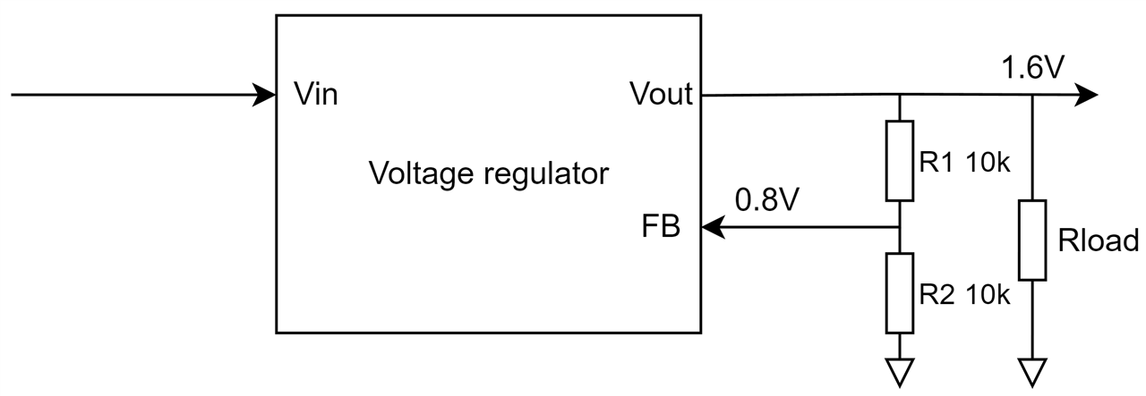
After few days of thinking I realized that standard buck regulators (I have plenty of them in my lab) can be configured in such way. Normally, buck converters are connected as shown on the following diagram. On the output they have connected voltage divider which set the output voltage. Inside the regulator there is voltage reference (for example, 0.8V) and regulator work in way that it adjusts output voltage to match voltage on the feedback pin equal to the internal reference. If the voltage on FB pin is lower, that it regulates output higher to compensate this error and similarly if for some reason voltage on the output increase (thus voltage on FB pin also increase), then it turns off the switch which cause output voltage to fall down back to right level.

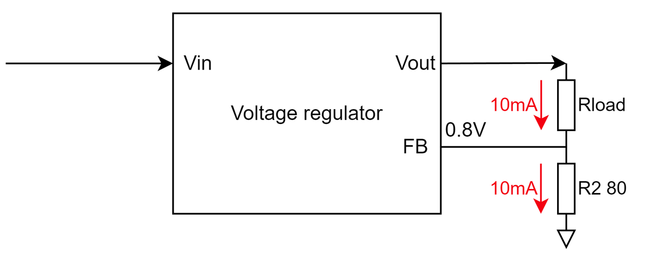
The behaviour of regulating voltage up and down is exactly what we need for constant current source. The only thing we need to achieve is that voltage on the FB will correspond to current flowing through the load. This is easily achievable by resistor, because voltage drop on resistor is proportional to current flowing through the resistor based on ohm law. So, idea is, that if we adjust R2 value to match reference voltage (0.8V) at desired current, the regulator will achieve that current flowing through R2 will be constantly at this level. Additionally, from Kirchhoff law we know that the same current flows through R1 no matter of its value and this is exactly what we need. To achieve current of 10 mA we need to set R2 to R = U / I, ei. R = 0.8 / 0.010 = 80 ohms. Look that while we originally had R2 as a value in range of tens of kiloohms now we are in the range of ohms.

Actual reconnection of standard buck regulator module is quite a simple. Instead of connecting load between GND and VOUT, you need to connect it between VOUT and feedback pin. VOUT is usually directly accessible, but feedback pin is not. I resolved it by soldering wire to the original voltage divider to expose this pin from the module.

Additionally, there is no need to resolder original resistors of feedback divider. Onboard 10k ohm do not influence added external 80ohm resistor because from parallel resistance formula 80 * 10000 / (80 + 10000) = 79.36 ohm which is minor difference from desired 80 ohms. Even 5% THT resistor tolerance cause more significant error, so for simplification it is not need to desolder original low side feedback resistor. Additionally, there is no need to desolder high side voltage divider resistor. It will influence accuracy of our constant current source because it add additional current consumption which it subtract from current flowing through load, but because resistance is high, the current is low, so the error is also quite a small (when powered from 5V source, maximum current is (5 – 0.8) / 10000 = 0.42mA.
Measurement circuit
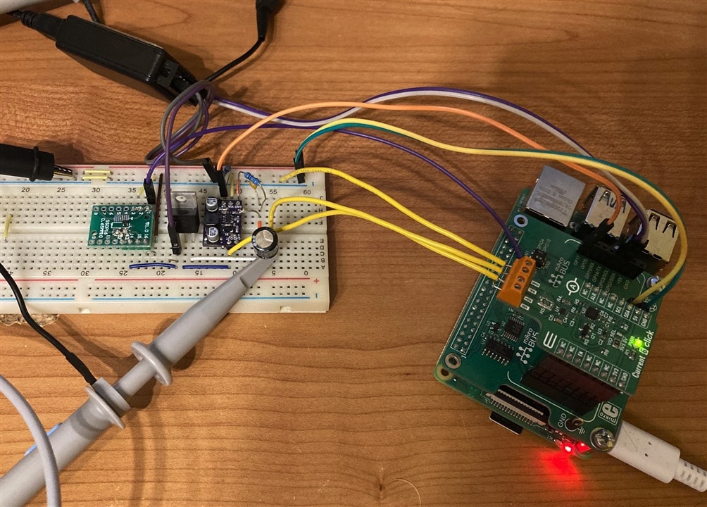
The Buck regulator used above I originally used for charging the supercapacitor. As mentioned at the beginning I originally used CSA, more precisely I used MAX40080 CSA which I used last year as part of Experimenting with Current Sense Amplifiers. For discharging capacitor, I used NMOS transistor and finally, whole circuit was controlled by Raspberry pi. But there were some pitfalls.

Triggering charger by CSA interrupt
The biggest issue is that CSA is connected to the Raspberry Pi using I2C bus which is quite a slow and it is not possible to transfer lot of samples to the Raspberry Pi. But MAX40080 has 64 sample FIFO which allows me to collect up to 64 consecutive samples collected at any speed. But problem is that I need to enable CSA right at the moment when I am disabling the discharge transistor. CSA is enabled by I2C transaction and transistor using GPIO, so it is impossible to do it at the same or at least with deterministic latency when using Raspberry Pi as a controller.
For resolving this issue, I implemented different approach. MAX40080 support generating interrupts when FIFO reaches some (configurable) level. I decided to drive discharge transistor directly by this interrupt. I need to add inverter to the way, but this I resolved by simple NAND gate (the same input signal is connected to both inputs, output is then inversion of input signal). The FIFO threshold which triggers the interrupt I configured to just 1 sample. So, after I enable the CSA, it collects first sample with capacitor discharging, then generates interrupt which cause discharge transistor to turn off and capacitor start charging. After some time, I collect 64 samples in the Python script and can analyse them while knowing that first sample is useless and there is possible ramp up at the beginning.
Capacitance Measurement
The analysis is quite a simple because when charging supercapacitor using constant current, voltage grow is linear. Speed of charge is directly dependent on the capacitor capacitance. Larger the capacitance, more time is it will take to charge, or in other words, voltage growth will be slower. Since I know sample rate and I know voltage growth between points I can simply estimate capacitance, but the results were not successful. I measured capacitance but it was systematically at the about of 70% of rated capacitance. For check I used technique to measure 100uF standard electrolytic capacitor also and compared with my DMM which can measure 100uF capacitance. The issue is that methodology of measuring capacitance in charge time and starting at zero is not precise because supercapacitors are designed to maintain they rated capacitance in discharge phase after they were charged. This is exactly what Cornell Dubilier manual requires to do and exactly what I did in my next experiment which I described in previous blog.
Pitfalls of using buck regulator as CC source
After completing this not very successful design I realized some caveats. The biggest caveat is that buck regulator is noisy which influence my measurement. For this reason, I was thinking about using LDO instead. Technically LDO can be used as CC source exactly as described in this blog, but in comparison with buck regulators many LDO do not use feedback way to set output voltage but has preset voltage or other mechanism is used to set output voltage. So, I did not find any LDO configured in this way, but at the meantime I was searching for some details about generating CC using LDO and I found app note from Maxim which teach me to use LDOs differently for generating CC and this method I used in my successful experiment described in previous blog.
Additionally, I realized that for precise measurement I need higher resolution ADC. MAX40080 has 12-bit ADC and with limited resolution on time domain consisting of 64 samples, even change in single LSB cause shift in the measured value. For this reason, in my final capacitance measurement experiment I replaced CSA by 24-bit high resolution ADC which has significantly lower sample rate, but after redesigning experiment it was not issue.
Discharging by constant current using MOSFET current mirror
At last, I needed to change methodology by measuring discharging phase instead of charging and for this reason I rather needed constant current sink instead of source and naturally, buck regulator configured as described above can’t do this (or can, but I am not sure if it will work, because it causes lower input voltage to the internal controller. With LDO it works).
Idea which I tried is using current mirror. Current mirror is quite a simple circuit which drives transistor gate to allow passing the same current which flows on the other side. Idea of constant current sink using mirror is that on one side I will generate constant current from known voltage (for example 3.3V from Raspberry Pi) and known resistors, and on other side I connect charged supercap which will discharge at a rate of current set on other side. The property of this circuit is that it requires two MOSFETS or BJTs with exactly the same properties, but my actual finding is that even when using exact MOSFETS the current on sides are not equal. But biggest issue which I realized is that even on one side current is constant, on other it slightly changes over applied voltage which makes source non-constant adds error to the measurements. Such error is hard to analyse and compensate. For this reason, I gave up, current mirrors as constant current sinks in this application and rather used LDOs as described in previous blog post.
Conclusion
This is all from my blog. In this blog I described some techniques which originally looked handy at the first look but at the end I all of them replaces and redesigned my capacitance measurement circuit driven by Raspberry Pi and Python. In next blog I will describe another experiment. I currently try to evaluate how much energy can supercapacitors store and compare (but not only) two 1F capacitors which I have in the kit. I am still wating for some PCBs, but I should receive them soon according to tracking information.
Thank you for reading this blog. Feel free to write comment below. I welcome any feedback. Have a nice day.
Netx blog: Effective Energy Capacity Evaluation


Top Comments
-

DAB
-
Cancel
-
Vote Up
+1
Vote Down
-
-
Sign in to reply
-
More
-
Cancel
-

rscasny
in reply to DAB
-
Cancel
-
Vote Up
+1
Vote Down
-
-
Sign in to reply
-
More
-
Cancel
Comment-

rscasny
in reply to DAB
-
Cancel
-
Vote Up
+1
Vote Down
-
-
Sign in to reply
-
More
-
Cancel
Children