Intro
This experimenting with supercapacitors design challenge was a great way to learn about supercapacitors, everything from how they are made and what handling precautions are needed to their performance and what applications they are good for. After I had researched supercapacitor applications, I had put together an ambitious project proposal which did not play out according to plan, but that is sometimes the way ambitious projects go. I like to learn by doing new things and really enjoy the design aspect of personal projects. In this project I wanted to learn about supercapacitors by designing a super capacitor meter and several supercapacitor applications.
The supercapacitor meter idea came about because I do not have a meter that can measure supercapacitors. To design such a meter I first had to research the measurement methods recommended for supercapacitors and why these methods are needed. Fortunately Cornell Dubilier has published guidelines and technical descriptions that were excellent in helping me understand the technology and its requirements.
The project had delivery issues with extra components I ordered to develop some applications. Some of the key components did not arrive in time and those applications had to be abandoned.
The capacitance meter development was plenty challenging on its own though. It is pretty ambitious to try to design a high performance instrument in a few weeks, and this definitely proved to be the case.
I did research all the applications I wanted to build and designed the systems and ordered the parts and some of them did arrive. Thankfully enough arrived to allow building the SuperCap Magic Meter, although even that one is still missing a voltage reference chip.
To keep the blog to a reasonable size it will focus on the meter I actually built even though considerable effort was involved in designing the other applications as well. If I have time today, I will put together a supercapacitor remote thermometer based on some parts from a previous project. I did design a chassis for it that will house Cornell Dubilier supercapacitors and I did receive a capacitor balancing module to ensure none of the capacitors sees high voltage.
SuperCap Magic Meter Circuit Design
Supercapacitors achieve high capacitance by designing porous activated carbon fiber electrodes that result in an astounding surface area amounting to thousands of square meters per gram of electrode. This electrode structure has such narrow pores it can take time for ions to physically migrate into all locations, so it can take some time at voltage for these capacitors to reach full capacitance. Measuring supercapacitors requires understanding the temporal effects of physical ion diffusion into porous electrodes and designing a measurement cycle that yields a predictable result.
The meter circuitry is designed into an Arduino shield which will plug onto an Arduino Uno R4 Minima. This MCU has a 14 bit A/D and a 12 bit DAC that will be used with the shield, allowing the voltages and currents to the supercapacitor under test to be measured and controlled. There is a 6 position rotary switch that selects which mode the meter will operate in. The charging circuit will charge at a constant 100 mA and the discharging circuit will discharge at a programmable rate set by the DAC. The reason for doing the schematic now is that I need to get the PCB on order to stay on schedule.
Here is a description of the circuit and its operation:
Here is the schematic.....
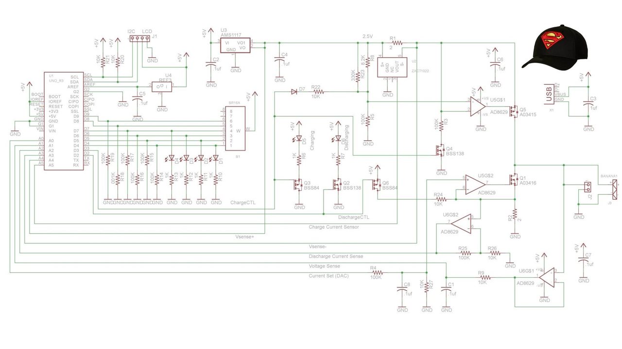
Basically the circuit includes a constant current source fixed at around 100 mA and a separate variable current sink, both can be turned on and off by the UNO R4, which also can monitor voltages across both current shunts and across the supercapacitor under test. It also controls measurement cycles and the precise timing involved. For a constant current, capacitance can be calculated from the time taken to charge the capacitor. (C=i*dt/dv), or simply the capacitance equals the charge on the capacitor divided by the voltage and the charge can be calculated as the current multiplied by the charging time.
Accuracy is is affected by many things such as thermal drift of amplifiers, component values (and things that affect those values), accuracy of voltage references, A/D resolutions, etc. So all of these issues had to be addressed in the design.
Siince this is a one-off build, all voltages and currents can be calibrated by measurement with bench instrumentation. Likewise the components can be individually and precisely measured so it doesn't matter whet their tolerance is. All the opamps are chopper stabilized to eliminate offsets and thermal drift.
The capacitor voltage measurement is buffered by a high impedance unity gain amp to minimize stray leakage from the supercapacitor under test. There are a couple of extra control FETs to ensure the current shuts off completely when the MCU wants it off.
The discharge current is controlled by a DAC on the MCU. This is needed since the recommended measurement method suggests the discharge current should be 1 mA/F. I can adjust the current used for measurement but expect to use currents that are typical of the supercapacitor applications I might build. This could result in a slightly different capacitance values than yielded by other methods.
There is an redundant current sense chip which will not be populated because it doesn't improve current measurement accuracy.
The SuperCap Magic Meter Shield (PCB)
Parts Kitting
Assembling the PCB
I definitely like to include custom PCBs in my projects, they are fun to design and they add a polished aspect to the project. This one went together very smoothly.
Firmware
Here is the firmware developed for the Arduino Uno R4 Minima:
For some reason I cannot insert code right now, so here is the zip file... SuperCapFirmware.zip
Preliminary Test and Design Validation
Here is a picture f the initial test setup including the local torture tester.
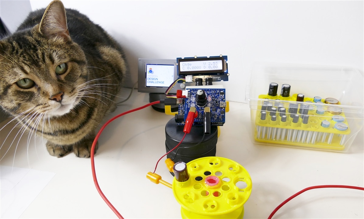
Functional Test Video:
SuperCap Magic Meter Mechanical Design
There were a number of items that were designed for this project including a case for the meter, a capacitor storage rack and a device-under-test carousel, all of which were 3D printed.
The SuperCap Rack
The SuperCap Rack design criteria are pretty simple but there are a few of them:
- It must safely hold all the supercapacitors supplied for the challenge and it would be nice to be able to store a few more.
- It must prevent capacitor leads from shoring to each other or to any other capacitor leads, or in fact to any random metal in the area.
- It must prevent the application of stress to the capacitors
- The rack must be transportable between bench and storage location without capacitors falling out or moving enough to short out
- The capacitors must be easily accessible
- It must be easy to place capacitors in the rack
- It should not take up too much space (the case supplied is very nice and it will be put to good use, but it is too big and not well suited to these requirements
The Capacitor Carousel Test Stand
he Capacitor Test Stand design criteria were slightly different:
- It must hold each size of capacitor securely without applying stress to the DUT
- It must perform the function of a third hand without risking hands touching leads
- It must provide access to the capacitor leads for something like mini-grabber test leads
- The capacitor must be held securely enough that it doesn't skitter away when trying to connect test leads
- It must be stable enough that the weight and stiffness of test leads will not move it or tip it over
Both the Rack and the test stand are covered in this video:
The SuperCap Magic Meter Chassis Design
The chassis is designed to snap together without any fasteners:
Labels
An interesting aspect of the mechanical design was trying to label the case. I tried a bunch of methods, some of which are shown here:
After installing the electronics and assembling the mechanical parts it was time to do some preliminary system tests:
Initial system demo
Note that this is still preliminary firmware with some suspect calculations and it is not calibrated well, so these results are not to be taken at face value. A lot more work went into it after this video was taken - I went through more than thirty sessions like this one. The video just provides some insight into where I was at during this part of the development process.
After getting to this stage it was time to get down to the detailed task of calibration. This involved numerous firmware updates and a lot of time consuming measurements. Supercapacitors just take a long time to charge and discharge, much like testing batteries.
Putting the SuperCap Magic Meter through its paces:
What went well:
- The circuit design worked properly as designed without requiring redesign - that is always very nice.
- Enough components arrived in time to build the PCB - this is always dicey these days
- The PCB arrived in time to build and test it. (I had made a big push to design it early)
- The PCB was easy to assemble - everything fit well
- The capacitor storage rack that isolated the leads to prevent shorts, worked very well, I am glad I designed it
- The capacitor-under-test carousel also worked well and turned out to be very useful
- The firmware worked well and was easy to tweak even though it is not my strong suit
- The mechanical case design turned out well (except for the label) Everything fit properly and it all snaps together without fasteners
- The custom banana test leads with grabber clips worked perfectly - the short leads prevented any tangling and minimized ESR contribution
In summary, all of the design aspects of the project turned out very well. That is what is all about for me.
What did not go well:
Where do I start?
- I did not understand supercapacitors very well at the beginning and needed to tweak my circuit design (at least it was before I ordered PCBs).
- I read an incomplete datasheet for the UNO R4 Minima and didn't realize they connected 2 analog channels to the I2C pins - very disappointing and it caused extra calibration
- A voltage reference chip did not arrive - caused more tedious calibration
- Key components for my other applications did not arrive (such as the radios)
- My toner transfer method of labelling did not work well (yet) I will get there eventually
- I still did not fully understand how to test LiC capacitors properly (at design time) and my circuit works far better on EDLC than LiC.
- Calibration was pretty tedious because of the apparatus not being close to my programming station
- ESR was especially problematic to calibrate - measuring milliohms accurately is finicky
Overall there were a lot more disappointments than I would want, but the meter does some things really well.
What was learned:
- I learned a lot about supercapacitors, which was of course a key objective of the project
- I learned a lot about how to make a supercapacitor meter and how to calibrate it.
It really was a project where new things were learned every week.
What would I do differently:
-
Order parts earlier
-
Implement better labels
-
Add modes to the switch to allow testing higher voltage capacitors closer to their rated voltage
-
Add modes to allow higher ESR devices to be measured without needing to reprogram the meter.
- Add modes to test at lower currents to allow smaller capacitors to be tested
Discussion
I really enjoyed the design and learning aspects of this project. The SuperCap Magic Meter worked very well at measuring voltage with great accuracy and high resolution, and it did a good job of measuring EDLC capacitance. It was not so good at measuring LiC's - it really needed to operate closer to their rated voltage.
2 of the LiC capacitors were fully discharged before they arrived although I inspected the packaging closely and it did not look like any were packaged in a position where they would have shorted in transit. These 2 caps would go to the charging voltage immediately but would not store any charge. The other LiC devices had enough charge to be above the recommended threshold but 2 of these also seemed unable to be charged to a higher voltage, the voltage would increase instantly but return as soon as the charging supply was removed. I did not find an explanation for this behavior and unfortunately didn't have time to condition the caps with longer soak times.
It was not easy to get it to do a good job on ESR, the inherent accuracy of the circuit is adequate, but there were timing issues as well as calibration issues. Measuring with high accuracy when everything is changing continuously, is a tall order.
The meter works well enough that I will use it whenever I need to measure an EDLC, but not well enough for me to use on LiC. Nevertheless, I like the meter and am very happy that I got a chance to design such an unusual instrument. It isn't often you get to try to design a completely new type of instrument where there are no examples to learn from. I haven't even seen a commercial meter that can do this, although an SMU would get most of the way there.
I ended up with a useful supercapacitor meter and nice selection of supercapacitors to use in future projects, just a few of the LiC devices are now questionable.
All in all it was a lot of fun to tackle this unique and ambitious project, the successes were gratifying and the failures were all good learning experience.
Next Steps
This experience will be useful for future projects and if/when the components I ordered show up, I will have a few applications already designed.
As a backup plan to the applications that suffered from long deliveries and ended up short of parts I designed a holder for Cornell Dubilier supercapacitors that will fit in my remote (Bluetooth), solar powered thermometer.
The firmware and android app already work. It is just a matter of printing the capacitor chassis and assembling the waterproof case. I managed to get the printing done on the last day of the contest and take some pictures.....
Here is what the capacitor chassis looks like and a picture of the rest of the remote system, which is based on an MSP430 MCU that consumes less than 1 mA.:
Capacitor Tray
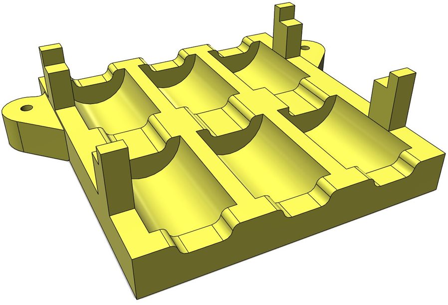
The tray can hold 6 capacitors but only 2 are needed for this application. There are two 25 F caps in the kit that will work.
Solar Thermometer System
My android weather app is running in the background - it communicates with the weather sensor system via Bluetooth.
The Bluetooth MSP430 is running its weather program - but powered from an external power supply instead of the supercapacitors in this image. It consumes less than 1 mA. These capacitors will run this MCU for about 1 hour continuous, but it can go to sleep and only wake up to measure temperature periodically, so it could run all night on capacitor power.
Two 25 F supercapacitors are shown in the yellow capacitor tray.
The solar panel is to the right of the capacitors.
Note the blue protection circuit card that can protect up to 6 capacitors from overvoltage.
This image shows how the supercapacitor chassis fits in the waterproof case.
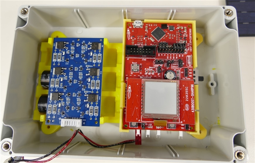
This image shows how the capacitor balance PCB fits over the supercapacitors.
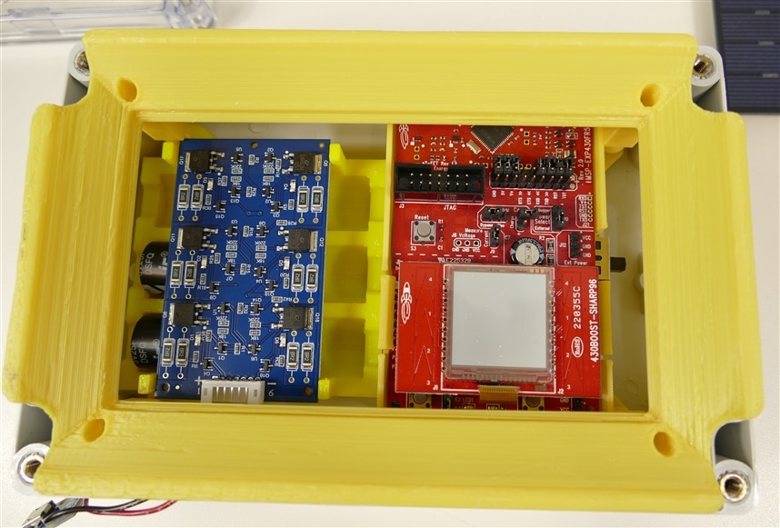
This image show how the solar panel frame fits over the electronics.
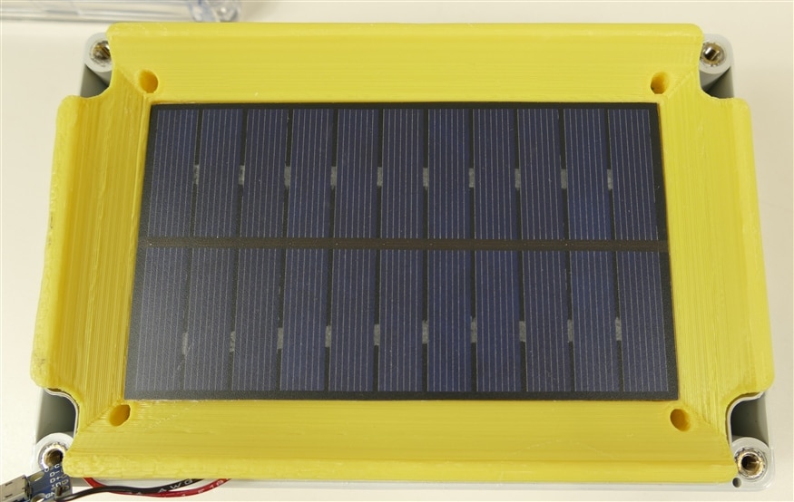
This image shows the solar panel in place.
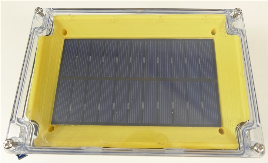
This image shows the system with its clear lid.
And the Odyssey continues....
Thank You
Thanks to element14 for selecting me to participate in this interesting design challenge and thanks to Cornell Dubilier for sponsoring the contest and supplying all the supercapacitors. I want to give a shout out to the other contestants - their work and comments were helpful and it was great to be on the same journey of discovery.
And thanks to all the members who have been following along and commenting along the way.
Links
The SuperCap Magic Meter Shield
SuperCap Meter Shield Functional Test
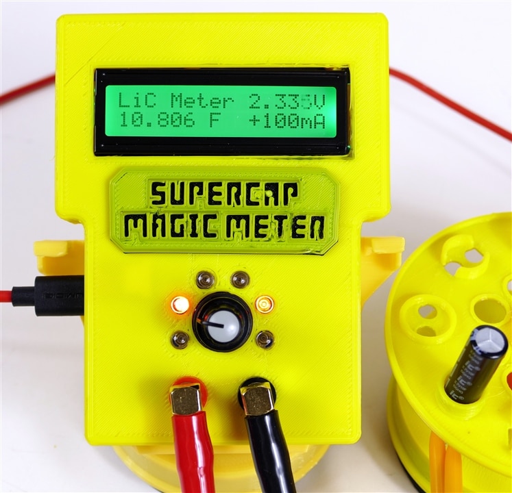
SuperCap Magic Meter - Operational
SuperCap Magic Meter - Experimenting with Supercapacitors
Experimenting with Supercapacitors Design Challenge
Cornell Dubilier Supercapacitor Technical Guide

Top Comments