element14 Community
element14 Community
    Register Log In
  • Site
  • Search
  • Log In Register
  • About Us
  • Community Hub
    Community Hub
    • What's New on element14
    • Feedback and Support
    • Benefits of Membership
    • Personal Blogs
    • Members Area
    • Achievement Levels
  • Learn
    Learn
    • Ask an Expert
    • eBooks
    • element14 presents
    • Learning Center
    • Tech Spotlight
    • STEM Academy
    • Webinars, Training and Events
    • Learning Groups
  • Technologies
    Technologies
    • 3D Printing
    • FPGA
    • Industrial Automation
    • Internet of Things
    • Power & Energy
    • Sensors
    • Technology Groups
  • Challenges & Projects
    Challenges & Projects
    • Design Challenges
    • element14 presents Projects
    • Project14
    • Arduino Projects
    • Raspberry Pi Projects
    • Project Groups
  • Products
    Products
    • Arduino
    • Avnet Boards Community
    • Dev Tools
    • Manufacturers
    • Multicomp Pro
    • Product Groups
    • Raspberry Pi
    • RoadTests & Reviews
  • Store
    Store
    • Visit Your Store
    • Choose another store...
      • Europe
      •  Austria (German)
      •  Belgium (Dutch, French)
      •  Bulgaria (Bulgarian)
      •  Czech Republic (Czech)
      •  Denmark (Danish)
      •  Estonia (Estonian)
      •  Finland (Finnish)
      •  France (French)
      •  Germany (German)
      •  Hungary (Hungarian)
      •  Ireland
      •  Israel
      •  Italy (Italian)
      •  Latvia (Latvian)
      •  
      •  Lithuania (Lithuanian)
      •  Netherlands (Dutch)
      •  Norway (Norwegian)
      •  Poland (Polish)
      •  Portugal (Portuguese)
      •  Romania (Romanian)
      •  Russia (Russian)
      •  Slovakia (Slovak)
      •  Slovenia (Slovenian)
      •  Spain (Spanish)
      •  Sweden (Swedish)
      •  Switzerland(German, French)
      •  Turkey (Turkish)
      •  United Kingdom
      • Asia Pacific
      •  Australia
      •  China
      •  Hong Kong
      •  India
      •  Korea (Korean)
      •  Malaysia
      •  New Zealand
      •  Philippines
      •  Singapore
      •  Taiwan
      •  Thailand (Thai)
      • Americas
      •  Brazil (Portuguese)
      •  Canada
      •  Mexico (Spanish)
      •  United States
      Can't find the country/region you're looking for? Visit our export site or find a local distributor.
  • Translate
  • Profile
  • Settings
Experimenting with Supercapacitors
  • Challenges & Projects
  • Design Challenges
  • Experimenting with Supercapacitors
  • More
  • Cancel
Experimenting with Supercapacitors
Blog SuperCap Magic Meter Circuit
  • Blog
  • Forum
  • Documents
  • Leaderboard
  • Files
  • Members
  • Mentions
  • Sub-Groups
  • Tags
  • More
  • Cancel
  • New
Join Experimenting with Supercapacitors to participate - click to join for free!
  • Share
  • More
  • Cancel
Group Actions
  • Group RSS
  • More
  • Cancel
Engagement
  • Author Author: dougw
  • Date Created: 14 Aug 2023 3:42 AM Date Created
  • Views 1883 views
  • Likes 14 likes
  • Comments 16 comments
  • dougw
  • SuperCap Magic Meter
  • experimenting with supercapacitors
  • supercapacitors
Related
Recommended

SuperCap Magic Meter Circuit

dougw
dougw
14 Aug 2023

image

Intro

This episode describe the circuit in my SuperCap Magic Meter. The meter circuitry is designed into an Arduino shield which will plug onto an Arduino Uno R4 Minima. This MCU has a 14 bit A/D and a 12 bit DAC that will be used with the shield, allowing the voltages and currents to the supercapacitor under test to be measured and controlled. There is a 6 position rotary switch that selects which mode the meter will operate in. The charging circuit will charge at a constant 100 mA and the discharging circuit will discharge at a programmable rate set by the DAC. The reason for doing the schematic now is that I need to get the PCB on order to stay on schedule.

The SuperCap Meter Circuit

Here is a description of the circuit and how it works:

You don't have permission to edit metadata of this video.
Edit media
x
image
Upload Preview
image

Here is the schematic of the supercapacitor meter shield:

image

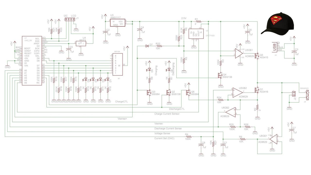
Basically the circuit includes a constant current source fixed at around 100 mA and a separate variable current sink, both can be turned on and off by the UNO R4, which also can monitor voltages across both current shunts and across the supercapacitor under test. It also controls measurement cycles and the precise timing involved. Those cycles will be described in the software blog when the software has been tested. However you can deduce that for a constant current, capacitance can be calculated from the time taken to charge the capacitor. (C=i*dt/dv).

Since this is a one-off build, all voltages and currents can be calibrated by measurement with bench instrumentation. The discharge current is controlled by a DAC on the MCU. This is needed since the recommended measurement method suggests the discharge current should be 1 mA/F. All opamps are chopper-stabilized to minimize errors due to offset voltages and offset drift. The capacitor voltage measurement is buffered by a high impedance unity gain amp to minimize stray leakage from the supercapacitor under test. There are a couple of extra control FETs to ensure the current shuts off completely when the MCU wants it off.

There is an redundant current sense chip which will not be populated because it doesn't improve current measurement accuracy.

There are still a couple of tweaks in the works, such as adding more test points, but the PCB will be complete in a day or so..

Discussion

The PCB is being designed early to allow time for it to be fabricated.  This is before the software can be worked on so it needs to have enough flexibility to accommodate software revisions. I did think about how the firmware might help improve performance and accuracy, but that is a lot different than writing code. The Uno R4 has a USB port that allows interfacing to a host computer if the instrument needs to eventually talk to other instruments and computers, however that is not in the plan for this project. Some of the design choices for the system were dictated by what I had on hand, but there is also a significant amount of ordering to procure everything needed. At this time there is so much planning and design work going on, it is tough to put blogs together.

This circuit took longer than expected to design and has morphed quite a bit as I learned more about how supercapacitors work and what needs to be done to measure their parameters.

Next I need to spend time on the other 5 systems to get their PCBs designed and make sure all needed parts are at least on order. I have already ordered a bunch of stuff, but until the detailed design is done, I won't be sure I have everything on order.

Links:

 The Magic of SuperCaps 

 SuperCap Magic Meter Circuit 

 The SuperCap Rack 

 The SuperCap Magic Meter Shield 

 SuperCap Meter Shield Functional Test 

 SuperCap Magic Meter - Operational 

 SuperCap Magic Meter - Experimenting with Supercapacitors 

Experimenting with Supercapacitors Design Challenge

Cornell Dubilier Supercapacitor Technical Guide

Cornell Dubilier Supercapacitor Handling Guidelines

Challengers

Leaderboard

  • Sign in to reply
  • dang74
    dang74 over 2 years ago

    You did an excellent job explaining the circuit in the video.

    • Cancel
    • Vote Up 0 Vote Down
    • Sign in to reply
    • More
    • Cancel
  • dougw
    dougw over 2 years ago in reply to shabaz

    Constant current devices like this are very neat for sure. Worth a look, but they probably aren't ideal for my design due to their voltage drop, turn-on response and accuracy. I actually looked at several other ways of creating constant current before settling on opamps. Thanks for the cool suggestion, all ideas are welcome.

    • Cancel
    • Vote Up 0 Vote Down
    • Sign in to reply
    • More
    • Cancel
  • DAB
    DAB over 2 years ago

    Nice design Douglas.

    • Cancel
    • Vote Up 0 Vote Down
    • Sign in to reply
    • More
    • Cancel
  • shabaz
    shabaz over 2 years ago in reply to dougw

    Hi Doug,

    I don't know if this will help or not. It's probably a bit unorthodox and I don't know if it works (I'm still thinking on it), I had a slightly similar requirement, although I needed to charge/discharge at discrete rates. 

    The circuit below aims to do that, with the relay switches on the left (i.e. a single DPDT relay) selecting charge or discharge mode. The 2-pin connector on the left is where the DUT gets attached.

    There is just a large bank of "constant current" JFETs, e.g. part code NSI45030 which is 30 mA (for instance). So, if I used that, then I can charge/discharge at rates of 30, 60, 90 mA and so on, just limited by how many of those devices I use (they are very low-cost, so it's inexpensive). They get reused for both charge and discharge, depending on the relay state.

    Anyway, I've not put much thought into it yet.. there may be serious issues! I think in principle it could be made to work, and is very low cost.

    image

    • Cancel
    • Vote Up 0 Vote Down
    • Sign in to reply
    • More
    • Cancel
  • dougw
    dougw over 2 years ago in reply to michaelkellett

    Yes, it is going to be like testing battery charge / discharge cycles .... Frowning2

    The recommended 1 mA/F discharge doesn't help either.

    Unfortunately, I don't have an SMU.

    At least there is enough built-in smarts in this design to automate it and let it run unattended.

    • Cancel
    • Vote Up 0 Vote Down
    • Sign in to reply
    • More
    • Cancel
>
element14 Community

element14 is the first online community specifically for engineers. Connect with your peers and get expert answers to your questions.

  • Members
  • Learn
  • Technologies
  • Challenges & Projects
  • Products
  • Store
  • About Us
  • Feedback & Support
  • FAQs
  • Terms of Use
  • Privacy Policy
  • Legal and Copyright Notices
  • Sitemap
  • Cookies

An Avnet Company © 2025 Premier Farnell Limited. All Rights Reserved.

Premier Farnell Ltd, registered in England and Wales (no 00876412), registered office: Farnell House, Forge Lane, Leeds LS12 2NE.

ICP 备案号 10220084.

Follow element14

  • X
  • Facebook
  • linkedin
  • YouTube