element14 Community
element14 Community
    Register Log In
  • Site
  • Search
  • Log In Register
  • About Us
  • Community Hub
    Community Hub
    • What's New on element14
    • Feedback and Support
    • Benefits of Membership
    • Personal Blogs
    • Members Area
    • Achievement Levels
  • Learn
    Learn
    • Ask an Expert
    • eBooks
    • element14 presents
    • Learning Center
    • Tech Spotlight
    • STEM Academy
    • Webinars, Training and Events
    • Learning Groups
  • Technologies
    Technologies
    • 3D Printing
    • FPGA
    • Industrial Automation
    • Internet of Things
    • Power & Energy
    • Sensors
    • Technology Groups
  • Challenges & Projects
    Challenges & Projects
    • Design Challenges
    • element14 presents Projects
    • Project14
    • Arduino Projects
    • Raspberry Pi Projects
    • Project Groups
  • Products
    Products
    • Arduino
    • Avnet Boards Community
    • Dev Tools
    • Manufacturers
    • Multicomp Pro
    • Product Groups
    • Raspberry Pi
    • RoadTests & Reviews
  • Store
    Store
    • Visit Your Store
    • Choose another store...
      • Europe
      •  Austria (German)
      •  Belgium (Dutch, French)
      •  Bulgaria (Bulgarian)
      •  Czech Republic (Czech)
      •  Denmark (Danish)
      •  Estonia (Estonian)
      •  Finland (Finnish)
      •  France (French)
      •  Germany (German)
      •  Hungary (Hungarian)
      •  Ireland
      •  Israel
      •  Italy (Italian)
      •  Latvia (Latvian)
      •  
      •  Lithuania (Lithuanian)
      •  Netherlands (Dutch)
      •  Norway (Norwegian)
      •  Poland (Polish)
      •  Portugal (Portuguese)
      •  Romania (Romanian)
      •  Russia (Russian)
      •  Slovakia (Slovak)
      •  Slovenia (Slovenian)
      •  Spain (Spanish)
      •  Sweden (Swedish)
      •  Switzerland(German, French)
      •  Turkey (Turkish)
      •  United Kingdom
      • Asia Pacific
      •  Australia
      •  China
      •  Hong Kong
      •  India
      •  Korea (Korean)
      •  Malaysia
      •  New Zealand
      •  Philippines
      •  Singapore
      •  Taiwan
      •  Thailand (Thai)
      • Americas
      •  Brazil (Portuguese)
      •  Canada
      •  Mexico (Spanish)
      •  United States
      Can't find the country/region you're looking for? Visit our export site or find a local distributor.
  • Translate
  • Profile
  • Settings
Experimenting with Supercapacitors
  • Challenges & Projects
  • Design Challenges
  • Experimenting with Supercapacitors
  • More
  • Cancel
Experimenting with Supercapacitors
Blog The SuperCap Magic Meter Shield
  • Blog
  • Forum
  • Documents
  • Leaderboard
  • Files
  • Members
  • Mentions
  • Sub-Groups
  • Tags
  • More
  • Cancel
  • New
Join Experimenting with Supercapacitors to participate - click to join for free!
  • Share
  • More
  • Cancel
Group Actions
  • Group RSS
  • More
  • Cancel
Engagement
  • Author Author: dougw
  • Date Created: 31 Aug 2023 10:49 PM Date Created
  • Views 1374 views
  • Likes 13 likes
  • Comments 7 comments
  • dougw
  • SuperCap Magic Meter
  • supercap meter shield
  • experimenting with supercapacitors
Related
Recommended

The SuperCap Magic Meter Shield

dougw
dougw
31 Aug 2023

image

Intro

This episode of the Experimenting With Supercapacitors Design Challenge covers the build of a supercapacitor meter shield that will mate with an Arduino Uno R4 Minima. The capacitance meter design takes advantage of the 14biit A/D on the UNO R4 to provide better resolution to capacitance measurements. The PCB was fabricated with a blue solder mask to match the UNO color. The shield provides the UNO with the ability to accurately control current into and out of a capacitor under test. There is a rotary switch that can select 6 different modes of operation. The circuit operation is described in a previous blog - linked below.

The Parts Kit

Here is a quick video of the kitted parts:

You don't have permission to edit metadata of this video.
Edit media
x
image
Upload Preview
image

I have been collecting and scrounging parts for a while. Some of the parts, such as transistors, LEDs and op-amps, are from stock I acquired before even discovering element14. The display is from an element14 prize that included some Grove modules. It is a bit of a process to go through old stock and look up all of their datasheets to see if they are suitable for the new project. There are still some parts that have been ordered but not arrived yet.

"Somebody" is going to develop an AI vision system that can recognize any part and find its datasheet. All of the technology and even most of the software to do this already exists.

The Build - Stuffing the PCB

image

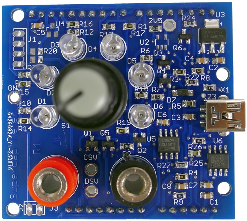
Here is a quick video of the build:

You don't have permission to edit metadata of this video.
Edit media
x
image
Upload Preview
image

A nice easy build, no components smaller than an 0805 or SOT23. The Arduino UNO form factor makes it a comfortable layout.

I'm using a new paperless workflow for soldering which is has pros and cons.

Paperless isn't quite as fast and the screen is not as conveniently located as where I clipped my paper docs, but there is more info available if I need it. Crossing off components as they get populated is not in the new workflow, so there is more checking involved. I will stick with it for a while and see if I can tweak the process and make it more productive.

Discussion

It was a bit of a wait for the PCB to arrive, but so far the design has gone exactly as planned, everything fits properly and initial powerup showed no surprises. The voltage reference for the MCU A/D has not arrived yet, but I can use the a rail voltage and independently measure the rail to achieve reasonable accuracy. I am waiting until I finish the meter build before diving into component testing. It isn't a suspense-building ploy, I just expect it to be a more interesting journey.

Next Steps

The project is behind schedule, so I need to pick up the pace.

Next I have to validate full functionality of the CCA and measure its components precisely. The precision of the capacitance meter will depend on measuring component values to an accuracy beyond what their nominal rated value would suggest.

Then I need to write some software to measure capacitance and characterize system performance.

Links

The Magic of SuperCaps 

 SuperCap Magic Meter Circuit 

 The SuperCap Rack 

 The SuperCap Magic Meter Shield 

 SuperCap Meter Shield Functional Test 

 SuperCap Magic Meter - Operational 

 SuperCap Magic Meter - Experimenting with Supercapacitors 

Experimenting with Supercapacitors Design Challenge

Cornell Dubilier Supercapacitor Technical Guide

Cornell Dubilier Supercapacitor Handling Guidelines

Challengers

Leaderboard

  • Sign in to reply
  • redcharly
    redcharly over 1 year ago

    Great idea

    • Cancel
    • Vote Up 0 Vote Down
    • Sign in to reply
    • More
    • Cancel
  • DAB
    DAB over 2 years ago

    Good start Douglas.

    Now on to the testing.

    • Cancel
    • Vote Up 0 Vote Down
    • Sign in to reply
    • More
    • Cancel
  • dougw
    dougw over 2 years ago in reply to genebren

    Foot controls Bulb - will have to think about that. (foot sized D-pad Relaxed)

    • Cancel
    • Vote Up 0 Vote Down
    • Sign in to reply
    • More
    • Cancel
  • genebren
    genebren over 2 years ago in reply to dougw

    Interesting approach.  I do like being able to see the schematic and layout while soldering, and from time to time I do pivot the monitor nearest my solder station in order to better see component positioning (sometimes my silkscreening gets so crowded that it is difficult to match the labels to the component).  I was just thinking about using my laptop much like you are using your surface. I do like the idea of having the remote monitor/laptop mounted about the soldering station, as looking up is easier that constantly turning to look to side.

    I have often thought that using a video-based laser pointing system where the laser points to the current component and part bin (having a foot activated advance), like they did way back when we had board assemblers at work, would be a great way to go. Something to think about.

    • Cancel
    • Vote Up 0 Vote Down
    • Sign in to reply
    • More
    • Cancel
  • dougw
    dougw over 2 years ago in reply to genebren

    Fortunately I don't need glasses for anything closer than a couple of meters.

    The paperless flow - Instead of using printed schematic and PCB layout to show what goes where while soldering, I am using an MS Surface tablet to display the same info. The main problem is that the paper gets clipped right above my stereo microscope, where the Surface is on a side bench. At that distance its screen is not large enough to read values without zooming and scrolling. I may need to mount it above the microscope, but I would still need to put my iron down to scroll the display or switch from schematic to layout. I haven't tried to use voice commands for navigation yet, although it may be possible. (sounds like the subject of a new experiment)

    • Cancel
    • Vote Up 0 Vote Down
    • Sign in to reply
    • More
    • Cancel
>
element14 Community

element14 is the first online community specifically for engineers. Connect with your peers and get expert answers to your questions.

  • Members
  • Learn
  • Technologies
  • Challenges & Projects
  • Products
  • Store
  • About Us
  • Feedback & Support
  • FAQs
  • Terms of Use
  • Privacy Policy
  • Legal and Copyright Notices
  • Sitemap
  • Cookies

An Avnet Company © 2025 Premier Farnell Limited. All Rights Reserved.

Premier Farnell Ltd, registered in England and Wales (no 00876412), registered office: Farnell House, Forge Lane, Leeds LS12 2NE.

ICP 备案号 10220084.

Follow element14

  • X
  • Facebook
  • linkedin
  • YouTube