element14 Community
element14 Community
    Register Log In
  • Site
  • Search
  • Log In Register
  • About Us
  • Community Hub
    Community Hub
    • What's New on element14
    • Feedback and Support
    • Benefits of Membership
    • Personal Blogs
    • Members Area
    • Achievement Levels
  • Learn
    Learn
    • Ask an Expert
    • eBooks
    • element14 presents
    • Learning Center
    • Tech Spotlight
    • STEM Academy
    • Webinars, Training and Events
    • Learning Groups
  • Technologies
    Technologies
    • 3D Printing
    • FPGA
    • Industrial Automation
    • Internet of Things
    • Power & Energy
    • Sensors
    • Technology Groups
  • Challenges & Projects
    Challenges & Projects
    • Design Challenges
    • element14 presents Projects
    • Project14
    • Arduino Projects
    • Raspberry Pi Projects
    • Project Groups
  • Products
    Products
    • Arduino
    • Avnet Boards Community
    • Dev Tools
    • Manufacturers
    • Multicomp Pro
    • Product Groups
    • Raspberry Pi
    • RoadTests & Reviews
  • Store
    Store
    • Visit Your Store
    • Choose another store...
      • Europe
      •  Austria (German)
      •  Belgium (Dutch, French)
      •  Bulgaria (Bulgarian)
      •  Czech Republic (Czech)
      •  Denmark (Danish)
      •  Estonia (Estonian)
      •  Finland (Finnish)
      •  France (French)
      •  Germany (German)
      •  Hungary (Hungarian)
      •  Ireland
      •  Israel
      •  Italy (Italian)
      •  Latvia (Latvian)
      •  
      •  Lithuania (Lithuanian)
      •  Netherlands (Dutch)
      •  Norway (Norwegian)
      •  Poland (Polish)
      •  Portugal (Portuguese)
      •  Romania (Romanian)
      •  Russia (Russian)
      •  Slovakia (Slovak)
      •  Slovenia (Slovenian)
      •  Spain (Spanish)
      •  Sweden (Swedish)
      •  Switzerland(German, French)
      •  Turkey (Turkish)
      •  United Kingdom
      • Asia Pacific
      •  Australia
      •  China
      •  Hong Kong
      •  India
      •  Korea (Korean)
      •  Malaysia
      •  New Zealand
      •  Philippines
      •  Singapore
      •  Taiwan
      •  Thailand (Thai)
      • Americas
      •  Brazil (Portuguese)
      •  Canada
      •  Mexico (Spanish)
      •  United States
      Can't find the country/region you're looking for? Visit our export site or find a local distributor.
  • Translate
  • Profile
  • Settings
Experimenting with Thermal Switches
  • Challenges & Projects
  • Design Challenges
  • Experimenting with Thermal Switches
  • More
  • Cancel
Experimenting with Thermal Switches
Challenge Blog Blog #3: LED Life Booster/Extender
  • Challenge Blog
  • Forum
  • Documents
  • Files
  • RoadTests
  • Mentions
  • Sub-Groups
  • Tags
  • More
  • Cancel
  • New
  • Share
  • More
  • Cancel
Group Actions
  • Group RSS
  • More
  • Cancel
Engagement
  • Author Author: karthikrajagopal
  • Date Created: 27 Mar 2022 3:01 PM Date Created
  • Views 1837 views
  • Likes 9 likes
  • Comments 6 comments
  • thermal switch
  • kemet
  • reed switches
  • experimenting with Thermal Switches
Related
Recommended

Blog #3: LED Life Booster/Extender

karthikrajagopal
karthikrajagopal
27 Mar 2022

The block diagram:

The plan explained in the first blog was to use 4 thermal switches for more controlled and reliable sensing. The experimental setup uses 2 thermal switches instead of 4, since the outcome is the same.image

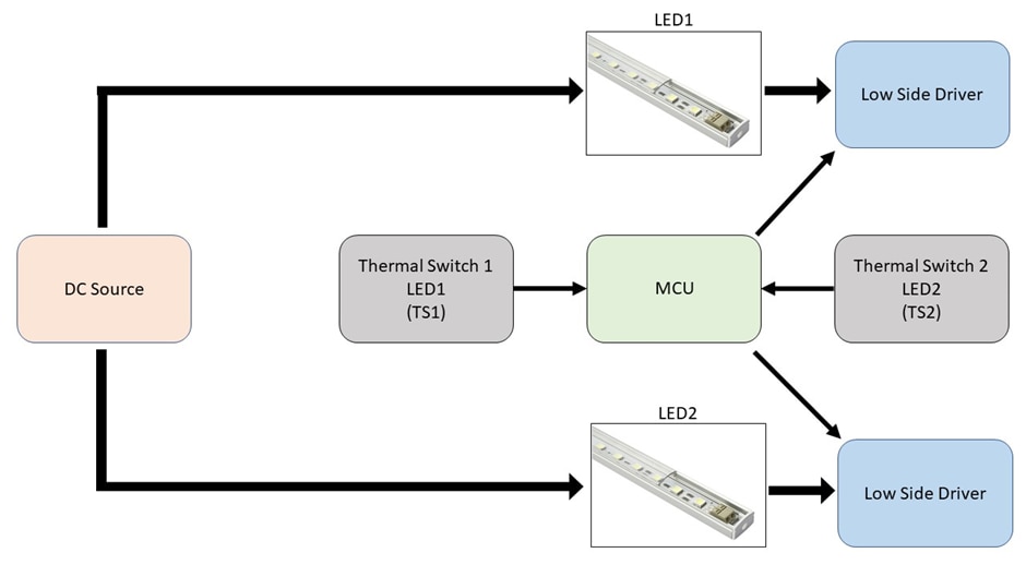
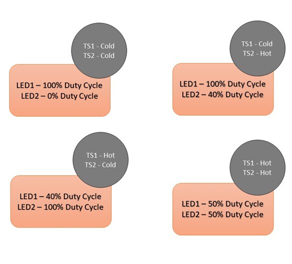
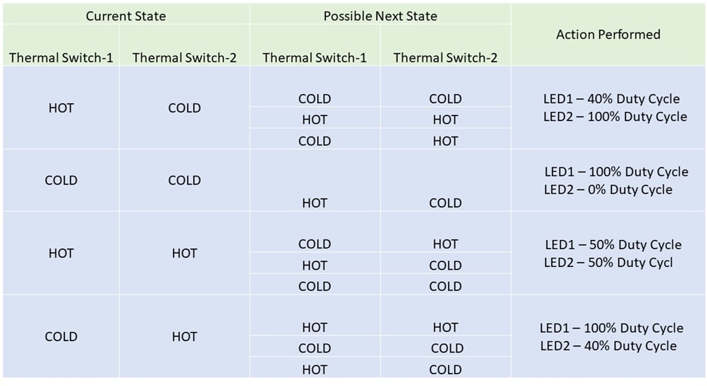
Developing the logic:

There are 4 possible combinations that can be achieved using the 2 thermal switches TS1 and TS2. The decision based on these 4 combinations would be meaningless since the current state transitions of TS1 and TS2 are independent of each other. Hence, the previous state of the switches is also to be considered to ensure smoother transition between various levels of brightness.

image

image

Arduino code:

#include <elapsedMillis.h>
elapsedMillis timer;
elapsedMillis timer1;
elapsedMillis timer2;
elapsedMillis timer3;
#define ledPin1 3    
#define ledPin2 9
#define thermal1 4
#define thermal2 5
byte y=255;
bool from10=0;
bool from11=0;
bool from01=0;
byte dly=5000; // state transition time
byte stand=20;

void setup() 
{
pinMode(4,INPUT);
pinMode(5,INPUT);
pinMode(ledPin1,OUTPUT);
pinMode(ledPin2,OUTPUT);
}

void loop() 
{
  
    if(digitalRead(thermal1)== 0 && digitalRead(thermal2)== 0)
    { delay(10);
      if(digitalRead(thermal1)== 0 && digitalRead(thermal2)== 0)   
    {if( (from10 == 1 || from11 == 1) && y!=255)
      {analogWrite(ledPin1,y);
       analogWrite(ledPin2,255-y);
        if(timer>= dly)
        {y++;timer=0;}
       
      }
      else if(from01==1 && y!=255)
      {analogWrite(ledPin1,y);
       analogWrite(ledPin2,255-y);
       if(timer>=dly)
       {y--;timer=-0;}
       
      }
      else
      {from10 =0;from11=0; from01=0;
      analogWrite(ledPin1,255);
      analogWrite(ledPin2,0);
      
      }
      timer2=0;
    }
    }
//*************************************************************************************
    else if(digitalRead(thermal1)== 1 && digitalRead(thermal2)== 0)
    {delay(10);
     if(digitalRead(thermal1)== 1 && digitalRead(thermal2)== 0)
       {if(timer2>dly)
        {analogWrite(ledPin1,y);
        analogWrite(ledPin2,255-y);
        if(timer>=dly && y!=stand)
        {y--; timer=0;}         
        from10=1;
        from01=0;
        from11=0;
      }
      timer3=0;
      }
    }
//*************************************************************************************
   else if(digitalRead(thermal1)== 0 && digitalRead(thermal2)== 1)
    {delay(10);
     if(digitalRead(thermal1)== 0 && digitalRead(thermal2)== 1)
        {if(timer1>dly)
          {analogWrite(ledPin1,y);
          analogWrite(ledPin2,255-y);
          if(timer>= dly  && (255-y)!=stand)
          {y++; timer=0;}        
          from01 = 1;
          from11=0;
          from10=0;
          }
          timer2=0;
          timer3=0;
        }
    }
//*************************************************************************************
    else if(digitalRead(thermal1)==1 && digitalRead(thermal2)==1)
    { delay(10);
      if(digitalRead(thermal1)==1 && digitalRead(thermal2)==1)
        {if(timer3>dly)
        { if(from10==1 && y!=125)
          {analogWrite(ledPin1,y);
           analogWrite(ledPin2,255-y);
           if(timer>dly)
           {y++;timer=0;}
           
     
          }
          else if(from01==1 && y!=125)
          {analogWrite(ledPin1,y);
           analogWrite(ledPin2,255-y);
           if(timer>dly)
           {y--;timer=0;}
           
          }
          else
          {from10=0; from01 = 0;
          analogWrite(ledPin1,125);
          analogWrite(ledPin1,125);
          }
         from11 = 1;
         timer2=0;
        }
        }
    }
}

Different states of brightness:

image

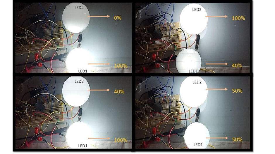
The picture1(top left corner) shows the initial brightness level. After entering the subsequent states of the logic, it returns back to the initial state only if both the thermal switches go below the 40°C mark.

The reason for maintaining  a 40-100% brightness level after crossing the initial state is to reduce the thermal expansion and contraction effects on the LED filaments (as mentioned by Gough Lui in my blog1 comment). This aspect is also taken care of by the software where the brightness level changes gradually depending on the set timer value.

  A 0-100% brightness level and a 40-100% / 100-40% brightness level both have the same light output with only subtle difference, which when used in a larger space would have negligible impact.

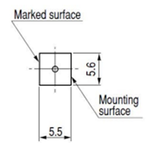
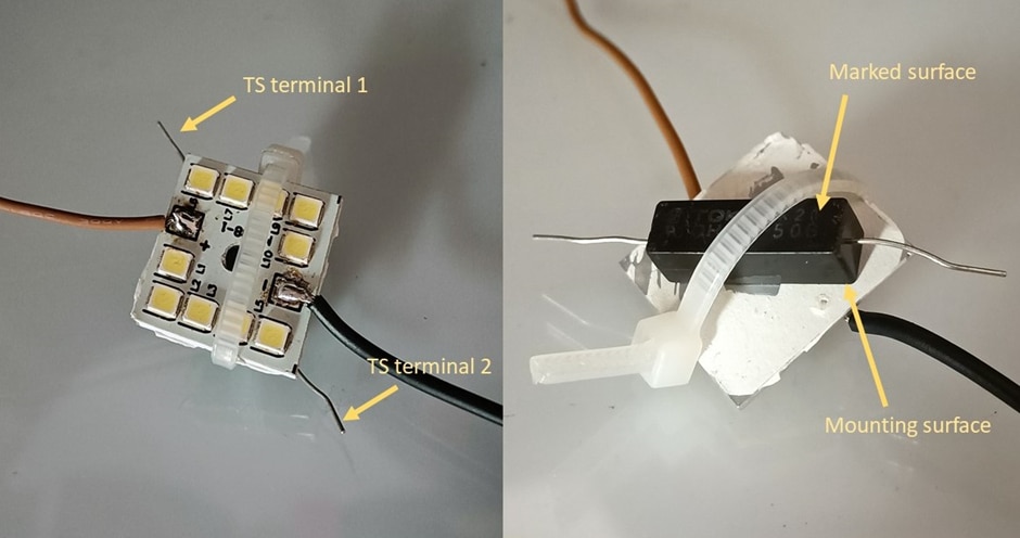
Mounting the Thermal Switch:

The OHD1-50B type KEMET thermal switch was mounted on to the backside of the heatsink. The switches were accurate and the cutoff temperature recorded was around 49°C.

image

image

The final output:

The circuit installation was done on the workbench and the change in light intensity was recorded. A video clip focusing the light bulbs is included along with a video of a user-perspective view of the light intensity change over the workbench. The transition time of the LEDs had to be reduced to 200ms and further the video had to be played at 2x speed for the light intensity change to be noticeable. So, it is understood that, on normal circumstances, the change in light intensity is unnoticeable.

In the video, the light intensity change can be observed by noticing the difference in the shadow cast by the wire at various instances of the clipping.

You don't have permission to edit metadata of this video.
Edit media
x
image
Upload Preview
image

Conclusion:

KEMET Thermal switches are useful for a variety of switching applications. They are accurate and a long-lasting solution as they have reduced metal fatigue due to no metal expansion. However, the downside could be the power rating. While their bimetallic counter parts have higher ratings, these reed switches have a maximum power rating of 75W, which in most cases can be a bit less  considering a direct series connection with the device’s mains input.

<Blog #2

  • Sign in to reply

Top Comments

  • karthikrajagopal
    karthikrajagopal over 3 years ago in reply to navadeepganeshu +1
    Thanks navadeepganesh! Yes, I have applied thermal paste on the back side of the heatsink. I have included the picture of it in 'Mounting the Thermal Switch' section.
Parents
  • navadeepganeshu
    navadeepganeshu over 3 years ago

    That's a nice demo, karthikrajagopal! Liked the way you implemented the logic on Arduino code. 

    Could use some type of thermally conductive adhesives/paste for enhancing the thermal input to the sensor in the LED module.

    • Cancel
    • Vote Up 0 Vote Down
    • Sign in to reply
    • More
    • Cancel
  • karthikrajagopal
    karthikrajagopal over 3 years ago in reply to navadeepganeshu

    Thanks navadeepganesh!
    Yes, I have applied thermal paste on the back side of the heatsink. I have included the picture of it in 'Mounting the Thermal Switch' section.

    • Cancel
    • Vote Up +1 Vote Down
    • Sign in to reply
    • More
    • Cancel
Comment
  • karthikrajagopal
    karthikrajagopal over 3 years ago in reply to navadeepganeshu

    Thanks navadeepganesh!
    Yes, I have applied thermal paste on the back side of the heatsink. I have included the picture of it in 'Mounting the Thermal Switch' section.

    • Cancel
    • Vote Up +1 Vote Down
    • Sign in to reply
    • More
    • Cancel
Children
No Data
element14 Community

element14 is the first online community specifically for engineers. Connect with your peers and get expert answers to your questions.

  • Members
  • Learn
  • Technologies
  • Challenges & Projects
  • Products
  • Store
  • About Us
  • Feedback & Support
  • FAQs
  • Terms of Use
  • Privacy Policy
  • Legal and Copyright Notices
  • Sitemap
  • Cookies

An Avnet Company © 2025 Premier Farnell Limited. All Rights Reserved.

Premier Farnell Ltd, registered in England and Wales (no 00876412), registered office: Farnell House, Forge Lane, Leeds LS12 2NE.

ICP 备案号 10220084.

Follow element14

  • X
  • Facebook
  • linkedin
  • YouTube