

Hello everyone!
From previous blogs:
From today's blog:
- Intro
- Block diagram
- Electronic diagram
- Software part
- Connectors usage
- Conclusions
Intro
This is the last blog I post for this challenge. In the end, I got to put my ideas into practice in a convenient way for me.
I started with the idea of getting to know the LattePanda board, because this is the main component to which I will connect most of the connectors received in the kit. I added a few components in addition to what I received in the kit. I had an easier start because LattePanda already came with a pre-installed operating system, Windows 10 Home (not that it would have been very difficult to install an OS myself). For the power supply, I tried to use something that meets the requirements suggested by the manufacturer, that is, a minimum 10W power supply.
A not so strong point that I discovered was the storage space, the LattePanda variant with 2GB RAM and 32GB storage is almost at the limit, but for me this did not end up causing me problems.
Block diagram
Having said that, I will start by presenting you a small block diagram, so that you can better understand what parts were used in this application.

The block diagram of this application contains:
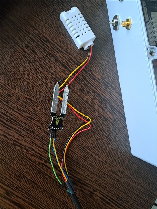
- temperature and humidity sensor DHT22, it is quite accurate and easy to implement in any system for monitoring ambient atmospheric parameters;
- soil moisture sensor, with this sensor the condition of the soil in the flower vase will be monitored;
- the display of the measured parameters is done continuously and in real time on an LCD display with I2C interface;
- the assembly control unit is represented by the LattePanda V1 platform;
- the measured parameters are graphically represented in the Node Red application in the form of an indicator clock and linear graph.
Broadly speaking, we have Inputs represented by the DHT22 sensor and moisture sensor, and Outputs are the means of display, locally on the LCD, and online through NodeRed.
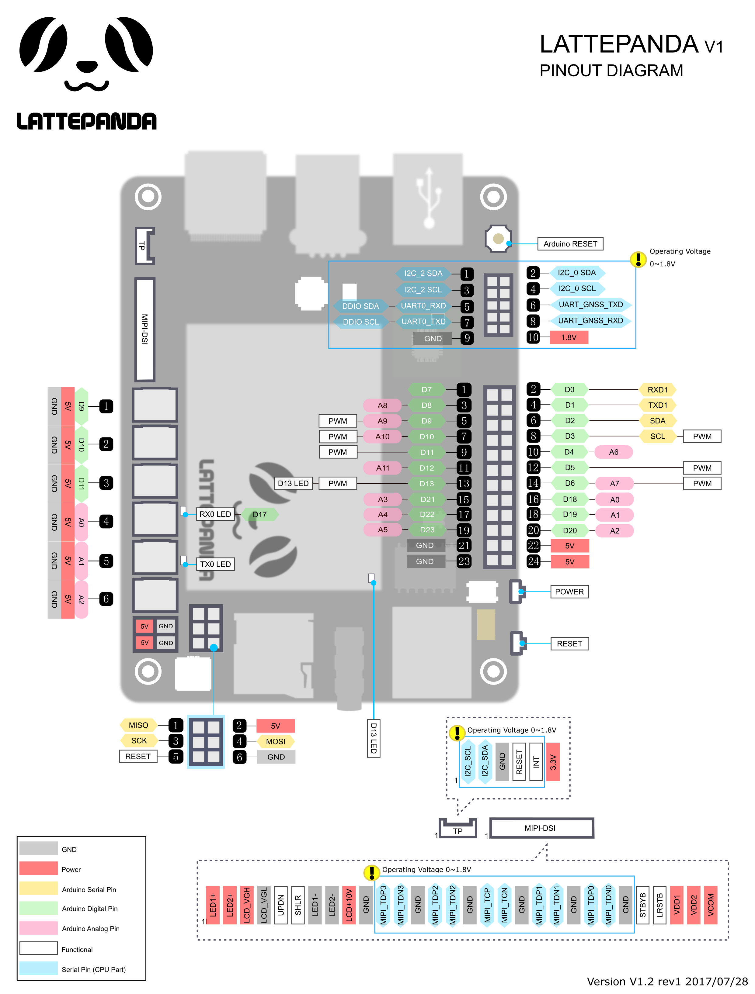
An overview for LattePanda V1 looks like this:
Electronic diagram
From here we can start building the electronic diagram:
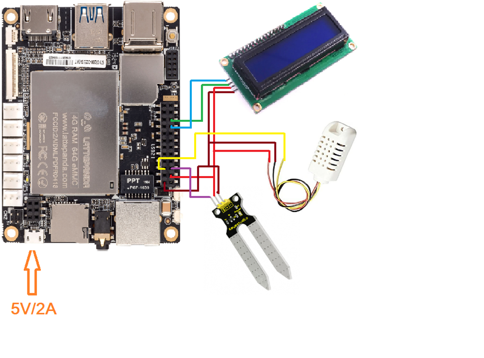
The 5V/2A power source will obviously power the LattePanda, and since the other components need a 5V source, which helps me a lot, they will work powered by the onboard 5V source on the LattePanda. To avoid confusion, DHT22 is connected to pin D23 according to LattePanda V1 pinout, moisture sensor is connected to A8. These two sensors are connected by the wires to the 4-pole MDR connector, because the sensors will be external, so they are placed outside the case.
The LCD display can be connected inside the case because it is quite visible, it is not necessary outside.
More details about the sensors can be found by accessing my other blogs.
The data is shown on the display, as can be seen in the picture below:

I think it is easy to understand what the displayed data represents. I presented the calibration of the moisture sensor in the previous blog, I left the soil in the vase dry for a few days, then I did tests with the sensor and when I poured water into the vase, I could see how the readings of the sensor changed. The temperature and humidity sensor helps to see how the parameters are in the ambient environment.
Software part
The process of creating the interface through Node Red is described as follows:
- the first step is to install Node Red instrumentally on the platform we work on, access the link https://nodered.org/docs/getting-started/local, following the steps presented;
- to run the application, access the Command Prompt terminal, execute the "node-red" command, then wait for it to start;
- to access the Node Red editor, access the link http://localhost:1880. A web page opens, and the flow I created is the one in the figure below: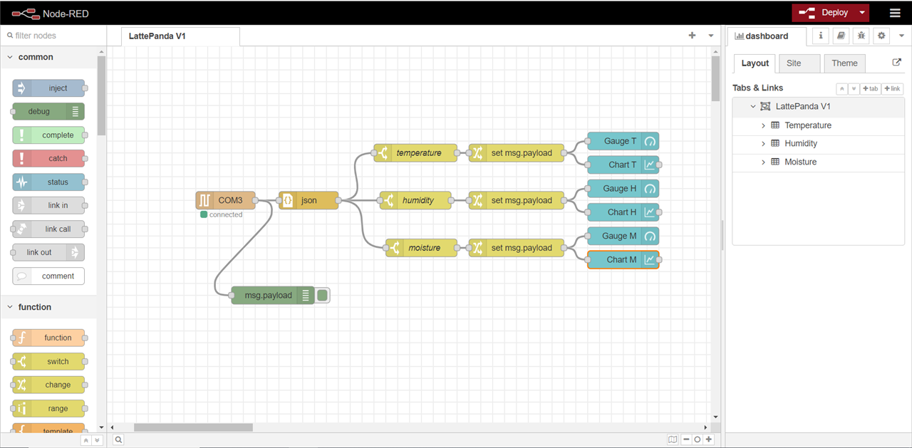
- in the palette menu on the left of the page, the nodes can be found, positioned on the workspace and their interconnection can be started.
The graphical interface created for this application comprises the following nodes:
- COMx is connected and receives the data from the serial port of the PC/laptop platform, it can be found in the network – serial in submenu;
- json converts from a JSON data string to a Java object representation, in both directions, found in the parser – json submenu;
- temperature/humidity/moisture is a node whose function is to filter information according to a specified property, it is found in the function - switch submenu;
- set msg.payload takes the data in the form of a message according to the set properties and directs it to the display objects, it is found in the function - change submenu;
- gauge is a node that adds an indicator clock widget, it can be found in the dashboard – gauge submenu;
- chart forms a graph based on the input values, it can be found in the dashboard – chart submenu.
To run the application, press the Deploy button at the top right of the web page, and from the submenu access Dashboard, which will open a new web page and the created interface will appear on the screen:
| {gallery}Node Red |
|---|
|
Dashboard: LattePanda V1 |
|
Expanded groups: Temperature, Humidity, Moisture |
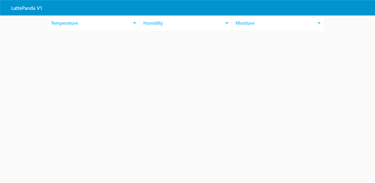
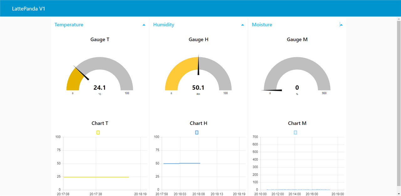
This web page includes a tab named LattePanda V1, three groups named in succession Temperature, Humidity and Moisture, each group contains two tools for displaying parameters, a clock and a graph.
The measured temperature is represented on a clock-type display with an indicator needle, the representation range is 0°C-50°C because in my home it does not happen that these values are exceeded. Immediately below it is a graph that shows the current evolution of the temperature in a linear way. In the same way, the humidity is represented on another graph, the representation range is 0-100%, and the soil moisture in the flower vase is displayed on another indicator clock and graph.
The graphical interface can also be accessed from another device, PC/laptop/mobile phone, since it is a web page, obviously an internet connection is required, and the IP address where the host, PC/laptop, is running at the time Node Red application, all you have to do is access the address http://IP_Host:1880 . One thing to keep in mind is that the Node Red application will not work if the COMx port is busy, ie another application on the PC/laptop is using it. So, in order to make this application work, it must be checked that the chosen COMx port is not blocked by the Arduino IDE programming environment or another program.
The logical structure of the Arduino sketch is quite simple, practically all that happens is that the Arduino Leonardo continuously receives data from sensors, which are then displayed by various methods, on the LCD display or through Node Red.
Speaking of Arduino, the program I loaded into the Arduino Leonardo from LattePanda is available below. This was written in the Arduino IDE, so I don't think it would contain much news. I used already known modules, and on the software side the library for the LCD display with I2C helps a lot. The reference values for the moisture sensor are purely approximate.
#include <Wire.h>
#include <LiquidCrystal_I2C.h>
LiquidCrystal_I2C lcd(0x27, 16, 2);

#include "DHT.h"
#define DHTPIN 23     // Digital pin connected to the DHT sensor
#define DHTTYPE DHT22   // DHT 22  (AM2302), AM2321
DHT dht(DHTPIN, DHTTYPE);

byte degree[8] = {
  0B00111,
  0B00101,
  0B00111,
  0B00000,
  0B00000,
  0B00000,
  0B00000,
  0B00000
}; // create degree sign

/*
  #   0~300     dry soil
  # 300~700     humid soil
  # 700~950     in water
*/

void setup() {
  Serial.begin(9600);
  lcd.init();
  lcd.clear();
  lcd.backlight();
  lcd.createChar(0, degree);
  dht.begin();

}
void loop() {

  float h = dht.readHumidity();
  // Read temperature as Celsius
  float t = dht.readTemperature();
  int moisture = analogRead(A2); // attach moisture sensor


  Serial.print("{\"temperature\":");
  Serial.print(t);
  Serial.println("}");
  Serial.println("{\"temperature\":" + String(t, 2) + "}");

  lcd.setCursor(0, 0);
  lcd.print(t);
  lcd.setCursor(5, 0);
  lcd.write((byte)0);
  lcd.setCursor(6, 0);
  lcd.print("C");


  Serial.print("{\"humidity\":");
  Serial.print(h);
  Serial.println("}");
  Serial.println("{\"humidity\":" + String(h, 2) + "}");

  lcd.setCursor(9, 0);
  lcd.print(h);
  lcd.setCursor(14, 0);
  lcd.print("RH");

  Serial.print("{\"moisture\":");
  Serial.print(moisture);
  Serial.println("}");
  Serial.println("{\"moisture\":" + String(moisture) + "}");

  lcd.setCursor(0, 1);
  lcd.print("Moisture: ");
  lcd.setCursor(10, 1);
  lcd.print(moisture);
  lcd.print("%");


  delay(200);

  lcd.clear();

} // end void loop
Waterproof connectors usage
Regarding the waterproof connectors, I have to say that from a constructive point of view they look quite qualitative, they couldn't have it any other way given their prices. They were mounted quite well on the enclosure, the holes were already made, maybe a few caps for these holes would have been useful, so if I don't use a specific connector for example and cover it. I must also mention some changes that I had to make to the enclosure, for example, in order to mount the RF antenna as good as possible, I had to make cuts on the inside of the enclosure. A channel is positioned in the direction of mounting the connector, and since I had no way to cover the hole in the enclosure, I had to mount the respective connector (you can see what I mean in a blog of mine). A second job concerned the RJ45 connector, the package did not include screws for mounting, so I came up with some, but they did not fit perfectly on the thread, as a result, a screw broke, but in a stupid way . I did not force the insertion of the screw into the thread, but the screw broke when removing the plug. What I had to do to fix it can also be seen in a blog of mine. There were also some problems in the sense that at the beginning I could not secure the RJ45 connector very well and in a tougher test, let's say, with a lot of water, I could see how the water infiltrated next to the RJ45 connector. This can also be seen in my other blogs.
Also related to the connectors, I wanted to connect the RJ45 plug to the LattePanda, at first I didn't realize how I could do this because I don't have the possibility to check the connections, but following the two schemes below the connections can be made.
| {gallery}RJ45 |
|---|
|
RJ45 Pinout |
|
RJ45 Waterproof connector |
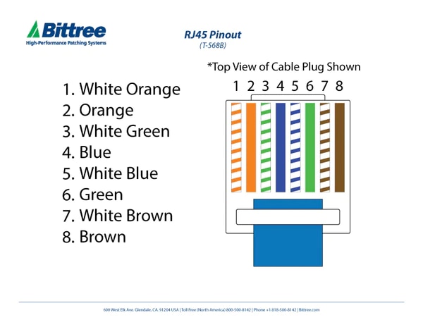
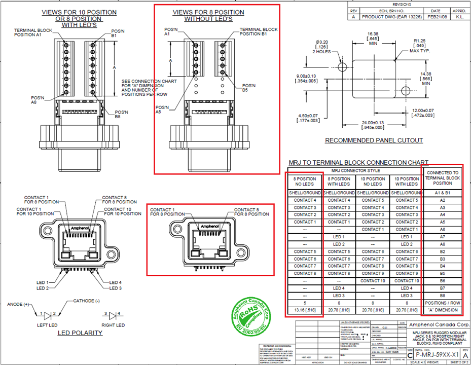
I tested with a cable connected between LattePanda and my router, and the connection worked, as you can see in the picture and video below.
https://drive.google.com/file/d/1WQ27UM7mpDN2pUUMYuys1yDBfPSbbLH1/view?usp=sharing
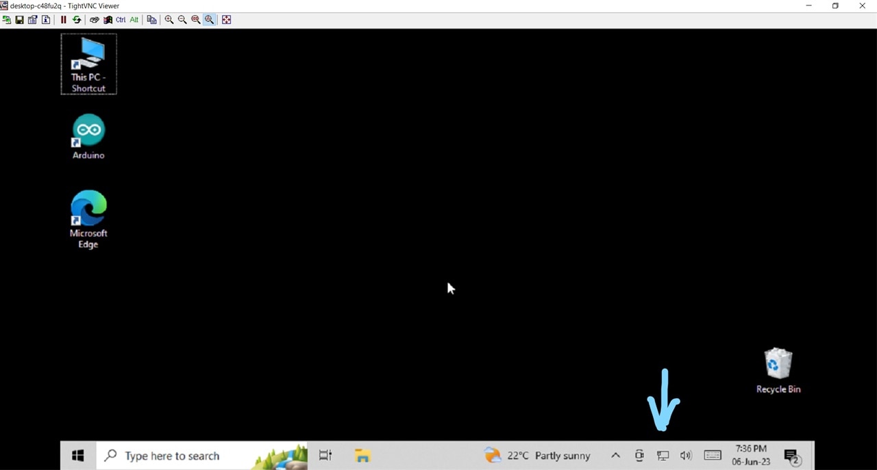
In the case of the antenna, in the datasheet I found the information that it is okay for use in frequencies up to 6GHz (I hope I am not mistaken), otherwise, on the LattePanda V1 we have WiFi in the 2.4GHz band. I asked a colleague who knows the field of transmissions better and he told me that it is not advisable to use anything, be it cable or coaxial, because it can disturb my signal quite a lot. I need to gather more information about this topic. Besides, I didn't connect any cable to the antenna outside. It would be nice to have a bat type antenna like the one from the router to mount it to the RF socket, on the outside of the case, obviously as long as it is compatible. Even so, I realized that neither of the two antennas (the one from the LattePanda or the one from the waterproof kit) have a very good performance, the signal is quite weak, using TightVNC to access the LattePanda remote I get to work harder because the WiFi connection is not strong enough. To be as good as possible, I still kept the antenna received with LattePanda. I need to buy a better antenna or a USB WiFi adapter.
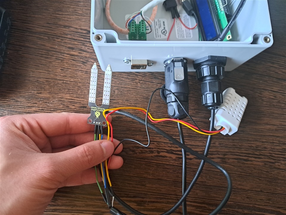
What I also used was the MRD connector with 4 contacts, through it I was thinking of mounting my two external sensors, DHT22 and soil moisture sensor (however, I think I will place DHT22 inside the enclosure, but I haven't decided yet) , but by chance I managed to tangle the wires between the connectors and ended up putting the power supply on the MRD connector.
I put the two sensors for LattePanda on the USB A connector, I only need two wires. As for this challenge I used a monitor only to access LattePanda and load the sketch in Leonardo, I will no longer use the USB connector for another purpose (to connect a USB stick for example). I only have one DHT sensor, I broke one, and it was interesting to be able to compare it with two sensors, that is, one inside the case and another outside, in normal atmospheric conditions, but for a warmer environment. Anyway, the most urgent thing I need to do is to mount the LattePanda in a proper case with a cooling system.
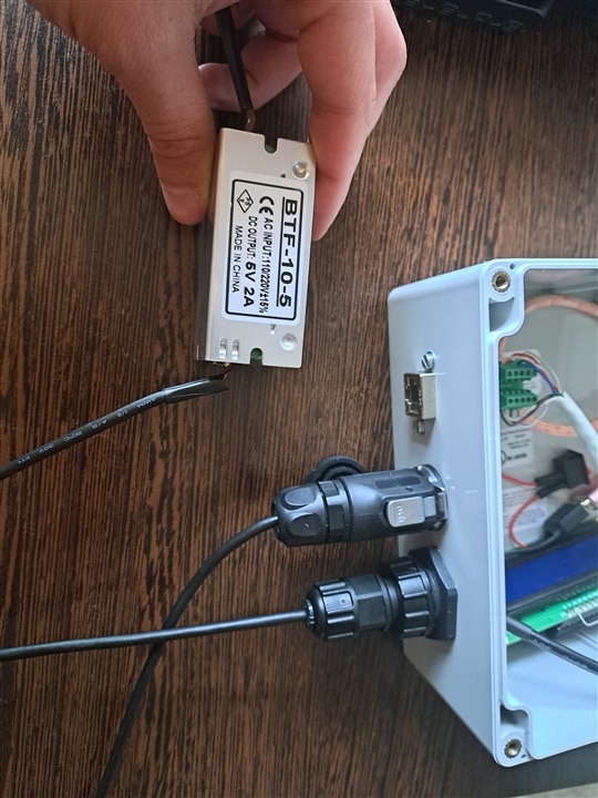
I didn't find a spare micro-usb cable, but I have a shorter one so I soldered some wires to make the power supply (I need to change the power source eventually with one that is more safely encapsulated, and that delivers 3A.).
For the other two connectors I need a coaxial cable, I found something like that at work. I still couldn't figure out what to connect to these two connectors, something useful would be desirable, I don't think I have a different sensor now. A special tool is also needed to be able to connect the coaxial cable to the connector, a certain model of pliers, to tie the shield to the ground of the signal.
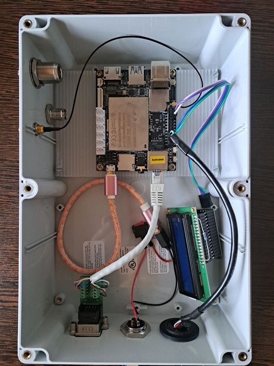
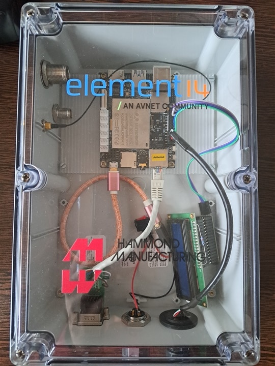
The enclosure is made of a fairly durable material, hard, in a good way, I happened to drop it on the ground, but it didn't break. After I tightened all the screws, it sealed quite well. I also did a heat test, I used a hot air heater, no problem. Okay, I know it doesn't have much power to heat, but it's a test and in the end I used what I could.
It's good that a transparent cover was chosen, it really helps sometimes to see if something is happening inside the case. By the way I mounted the LattePanda inside the enclosure (I can't really connect to the HDMI port to connect it to an external monitor), I will use it through the TightVNC tool, I would need a custom plate so that I can place it LattePanda more convenient, to be able to access all ports. Below you can see a short video. I didn't put the cover over the enclosure because I also used the antenna from LattePanda and it could have broken.
Below you can see a video as well as some pictures of the final setup that I made:
| {gallery}Setup |
|---|
|
IMAGE TITLE: THEN IMAGE DESCRIPTION |
|
|
|
IMAGE TITLE: THEN IMAGE DESCRIPTION |
|
IMAGE TITLE: THEN IMAGE DESCRIPTION |
|
IMAGE TITLE: THEN IMAGE DESCRIPTION |
|
IMAGE TITLE: THEN IMAGE DESCRIPTION |

Video: https://drive.google.com/file/d/1zoGSSCw1hXP7qH6HzNerVc6NnIEl0Bow/view?usp=sharing
I must say that the documents provided for this challenge were also useful to me, I found helpful information regarding the RJ45 connector, for example, or the RF antenna.
Conclusions
In conclusion, I would like to say that I enjoyed working on this challenge, even if I did not manage to use all the connectors. The experiments really kept me busy, I tried to test all the parts of the received kit and do tests to prove how waterproof these connectors are. I think that even if these connectors are more suitable for industrial use, they can also be part of a homemade project. Inevitably there are situations where you have to work more slowly, maybe you don't know some things, you need information and you have to look for it, a ew connectors require a tool to be able to properly connect the coaxial cable, and so on. For the RJ45 plug, it would be useful to provide suitable subs for mounting, maybe someone has a problem like mine. Also, cover caps made according to the model of the socket holes would be useful (this if the enclosure already has holes made).
Thank you Element14 Community!
Have a nice day!