


Recap
I am building a robotic system that identifies the charging port on an EV and automatically moves a charger arm to plug the charger in.
Past Forum Posts:
- DockBot - Part 1 - The Concept
- DockBot - Part 2 - Positioning with Aruco Markers
- DockBot - Part 3 - New Plan, New Hardware for Better Sensing
This part is about turning the Devastator chassis from Part 3 into something that actually drives, and getting the Arduino UNO Q to be the one driving it.
The new motors and chassis mods
In the last post I mentioned that the Devastator Chassis motors were burnt out and I had ordered a All Gear Motors, I received my motors went ahead and installed the replacement all-metal BO motor and found two problems - one I'd anticipated, one I hadn't. The original Yellow BO motors were L-shaped; the replacement is straight. Before I even ordered it I had checked for collisions and found that a flange with a nut, which connects the roof of the platform to the side, would be in the way. Fix for that is to cut the flange and replace it's functionality with a 3D printed bracket.
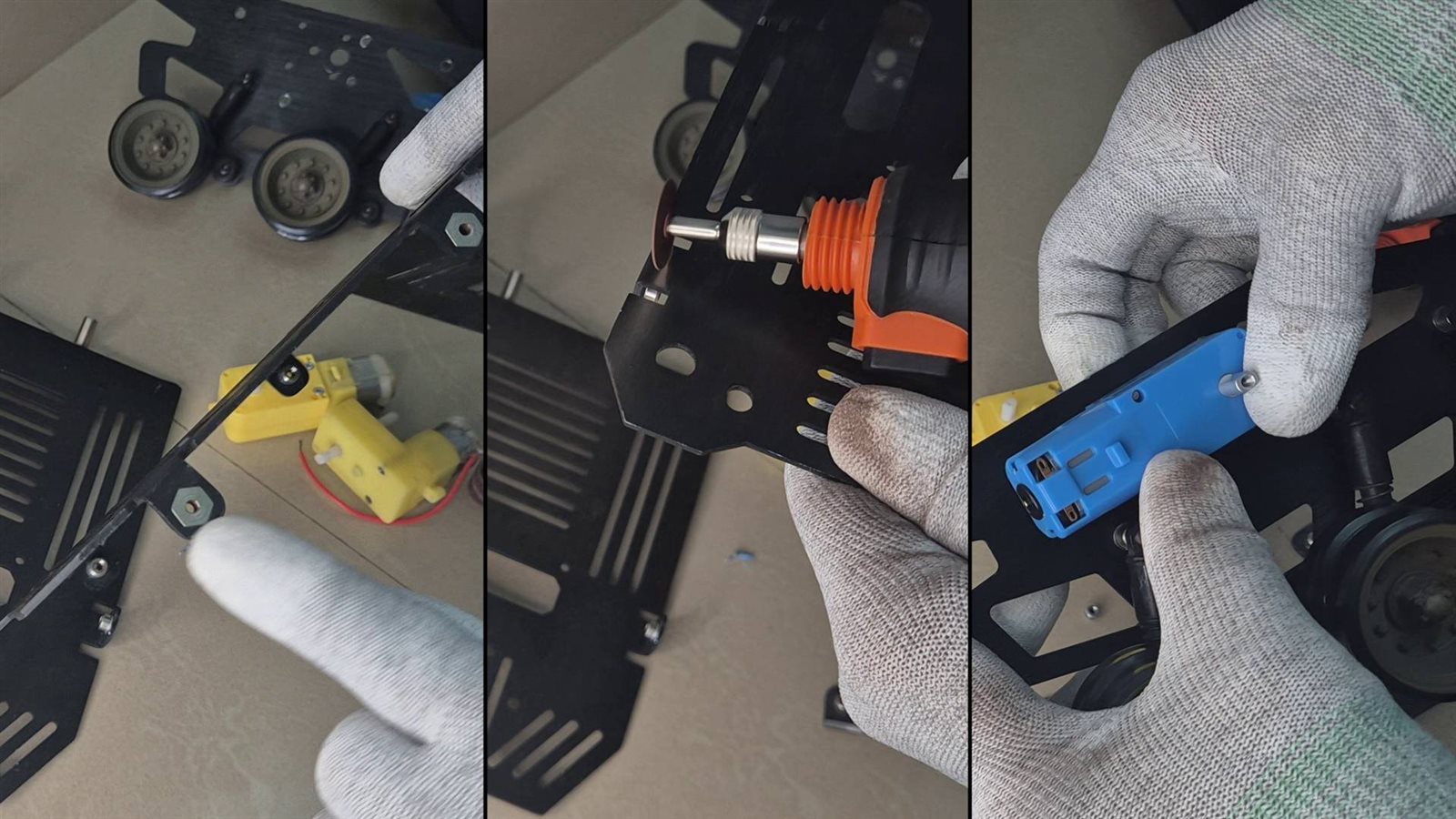
Below is a video of me modding the Chassis. Watch it only if you love watching such logs. Its a bore for others.
The second problem was new: a little plastic stub that I think holds one of the gears in place looked mechanically identical to the original but wasn't quite. There was a minor location difference, Had to drill out the location hole to get it to fit.
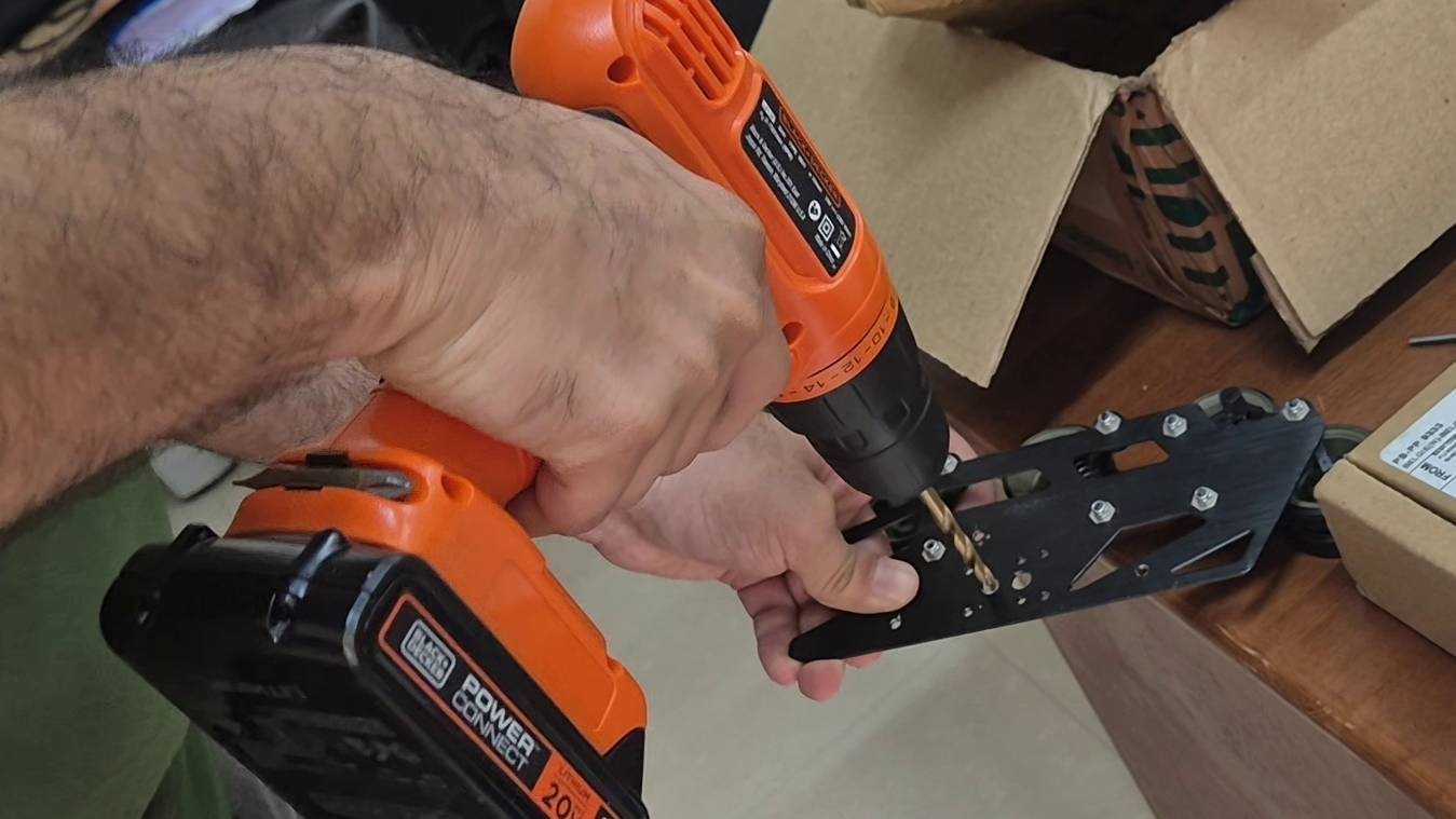
Both motors installed, tracks back on, and I confirmed both spin the right way before moving on to electronics.
The electronics
The Arduino UNO Q becomes the brain of the whole platform. The Qualcomm Dragonwing QRB2210 side runs Linux and acts as the overall controller - it'll receive positioning data from the Radxa Q6A about where the robot and the car actually are. The STM32U585 side handles the real time motor control loop through a DRV8833 driver.
As a mechatronics engineer I know that manufacturing differences between motors - different inertia and friction in the gear train, different friction in the track and wheel system - mean the two motors won't turn at exactly the same speed for the same commanded voltage. Sometimes you get lucky and the mismatch is tiny, but I didn't want to bet on luck, so I planned ahead for an encoder on each motor shaft, which is why I bought motors with a shaft on both ends in the first place. I'll be using a TLE5012B as a non-contact magnetic encoder for that - not wired up yet, more on that below. I am using TLE5012B just because I have surplus of it from another project, But there are more easier to procure and easier to interface encoders available.
For power, I'm using a 3500mAh 2S 7.4V Li-ION battery. The Arduino Q gets powered through its VIN pin (official power spec). During testing I found it needs a minimum of 6.7V to run reliably - the official docs say 7V, but that's presumably for full-load conditions. The motors are rated at 6V, so a buck converter in parallel brings that down to 5.9V before it reaches the motors via the DRV8833.
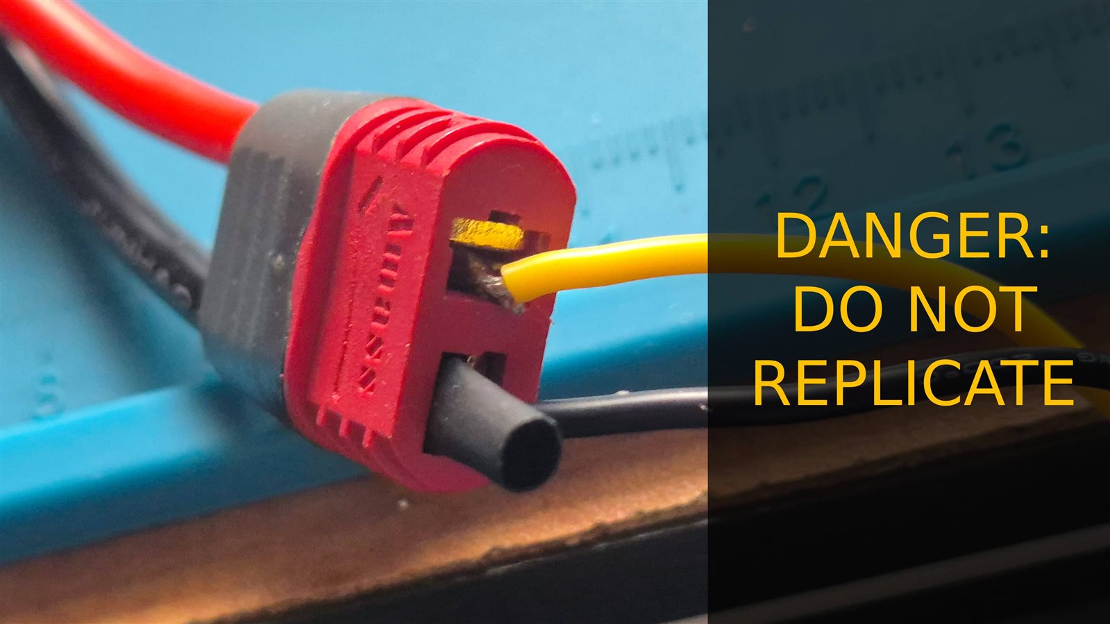
I made a custom perfboard PCB to house the DRV8833, a screw terminal for battery in, the motor leads, and a 2.54mm JST-XH connector carrying the 6V rail into the driver. The one snag: the battery uses a female T-Deans connector, and I didn't have a matching male one on hand. I had to do a makeshift, admittedly dangerous workaround to get power flowing for bench testing. I would not recommend anyone do what I did - that battery has a high discharge rate and is a genuine fire hazard if shorted. I've ordered the correct connector; whether it arrives before the submission deadline is a different question.
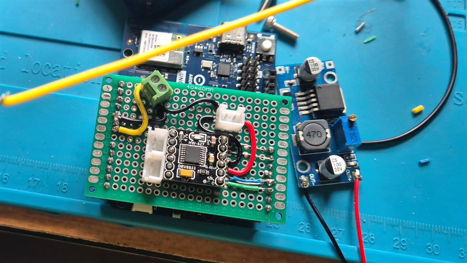
Perfboard driver PCB - DRV8833, screw terminals, JST-XH power in
The code
For Arduino UNO Q programming, I'm building on the work from the last design challenge - On the Line - where I disabled the bridge between the Dragonwing Linux side and the STM32, giving the STM32 full bare-metal control instead of going through the Arduino sketch layer. Same STM32CubeMX HAL project setup carried over, pins reassigned for this board.
For now I'm deliberately skipping the encoder and any PID control - the goal of this post is just getting the hardware moving, closed-loop speed control is a separate step.
The wire protocol between the Linux side and the STM32 is a tiny line-based ASCII format:
M <left> <right>   set track motor speeds, -255..255 each
S <id> <angle>     set servo <id> (0 or 1) to <angle> degrees, 0-180
H                  halt (motors only)
with a 500ms command-timeout fail safe in STM32 firmware - if no valid line shows up within that window it halts the motors on its own, so a crashed Linux-side process can't leave the tank driving into something:
void UartProtocol_Poll(void)
{
  if (s_line_ready) {
    s_line_buf[s_line_len] = '\0';
    handle_line(s_line_buf);
    s_line_len = 0;
    s_line_ready = 0;
  }

  if (HAL_GetTick() - s_last_command_ms > COMMAND_TIMEOUT_MS) {
    Motor_Stop();
  }
}
First bench test immediately turned up two bugs. One was the usual - the left motor's direction sense was wired backwards relative to the `M <left> <right>` sign, so a positive command drove it in reverse. Easy fix, just invert it in software rather than rewire anything.
The second one took longer to track down. With the DRV8833's DIR pin held HIGH, the driver alternates full-drive and brake every PWM cycle instead of the documented drive/coast behavior - so with DIR high, a small commanded duty was actually the fastest the motor would go, and a large duty stalled it. Completely backwards from what I expected. Once I figured that out, complementing the duty (`255 - magnitude`) whenever DIR is HIGH fixed it:
static uint32_t compute_duty(int16_t speed)
{
  uint32_t magnitude = (uint32_t)(speed < 0 ? -speed : speed);
  return speed < 0 ? 255U - magnitude : magnitude;
}
Both directions now scale proportionally from zero on the bench. There's still a small deadband near zero but that is due to the the PWM having too less duty to overcome the static friction. I'll deal with that later.
For actually driving the thing during bench testing, I have to credit the author of Hall W EV - Post 1 - The Wheels Are Turning (Mostly) tamadillo and hambreros for the idea of hosting a web UI directly on the UNO Q for manual control. I would have made a python tkinter GUI to tun on host computer. Only difference is I set mine up by hand instead of through App Lab - a plain Python http.server handler that serves a page with sliders and posts JSON to /api/drive, /api/servo, /api/halt, which get relayed straight down the serial link to the STM32:
Since the STM32 halts on a 500ms silence, the page has to keep resending the current slider values every 150ms while a slider is held - releasing it (or hitting Stop) sends H and stops the resend loop. I later added +/-1 and +/-5 bump buttons alongside the drag sliders, for the fine adjustments that are basically impossible to hit by dragging a slider with a mouse.
What's next
Encoder wiring and a basic speed-control loop are next on the STM32 side (Assuming the Diametrically polarized magnets come in time), then getting the Linux side actually talking guidance over the serial link instead of me driving it by hand with sliders with the Radxa showing the absolute positioning.
Final Notes
Devastator Chassis is a tank again. I feel I should some RGB lights, What do you say?


