


In my previous post, “EVA Guardian: The Incident Detection System,” I explored the safety side of the project, where the Arduino UNO Q and MPU6500 were used to detect different vehicle motion patterns using Edge AI. While detecting an accident is important, there is another equally important question for an electric vehicle:
What is happening to the battery that powers the vehicle?
Previous forum posts
Part 1: The Idea behind EVA Guardian
Part 2: The Architecture of EVA Guardian
Part 3: The Incident detection System in EVA Guardian
For this part of EVA Guardian, I started building the Battery Management and Battery Profiling Node.
The objective of this module is to continuously measure the battery's voltage, current and temperature, and use these parameters to derive meaningful battery information such as State of Charge (SoC), State of Health (SoH), energy usage and battery condition.
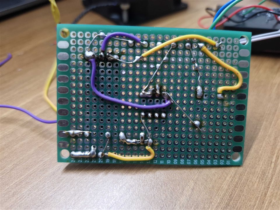
For the first prototype, I built the complete measurement circuitry on a veroboard and interfaced it directly with the Arduino UNO Q.
The Battery Management Approach
The battery used for this prototype is a 2-cell 18650 Li-ion battery pack connected in series. Each cell has a nominal voltage of approximately 4.2 V, giving a fully charged voltage of approximately 8.4 V. For the initial prototype, I am using an HX-2S-A2 2S BMS protection board to provide the basic battery protection functionality.The Arduino UNO Q is then used as the monitoring and intelligence layer above the protection circuit.
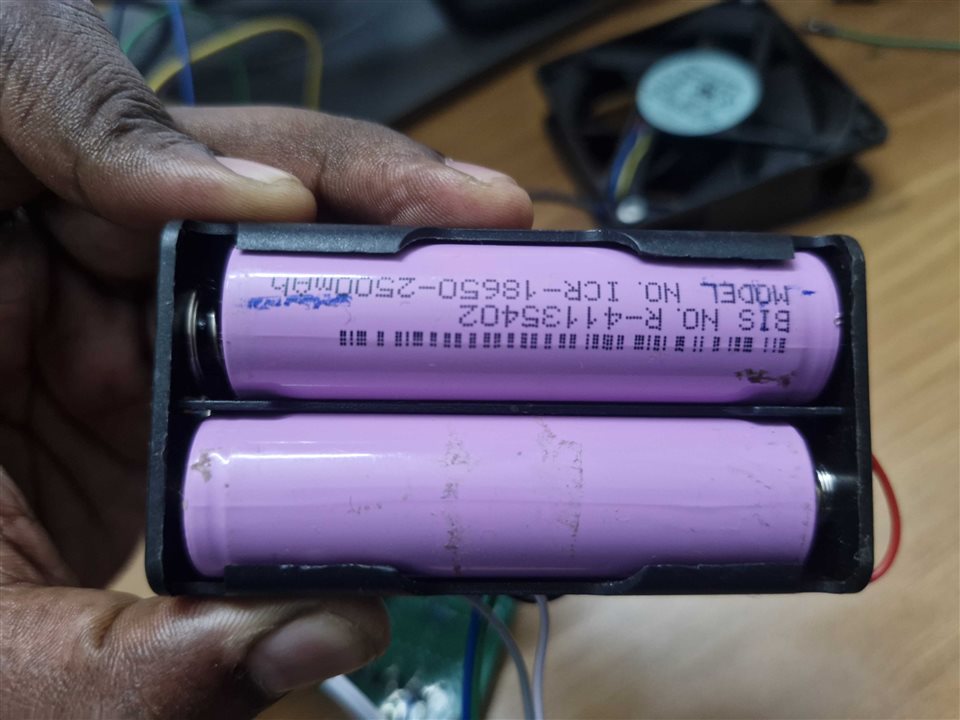
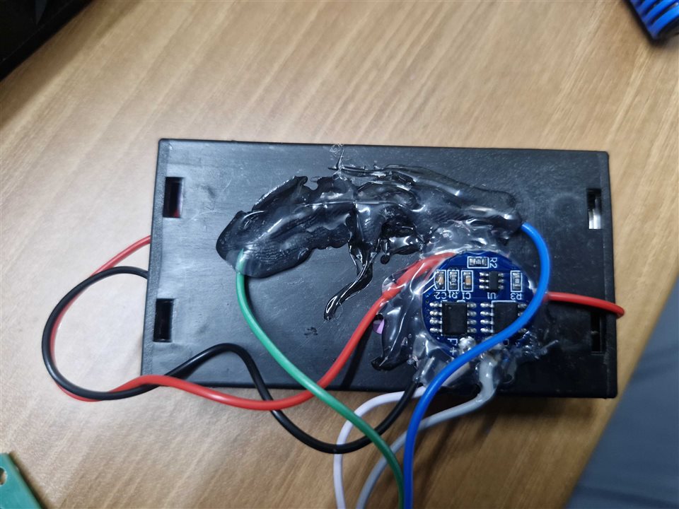
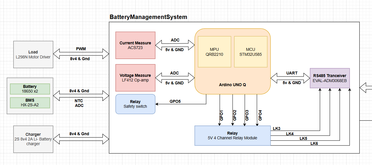
The basic architecture is:
Battery → BMS → Voltage / Current / Temperature Measurement → Arduino UNO Q → Battery Analytics
The three primary measurements are:
- Battery voltage
- Battery current
- Battery temperature
These measurements form the foundation for the higher-level battery calculations that I plan to implement.
Building the Measurement Circuit
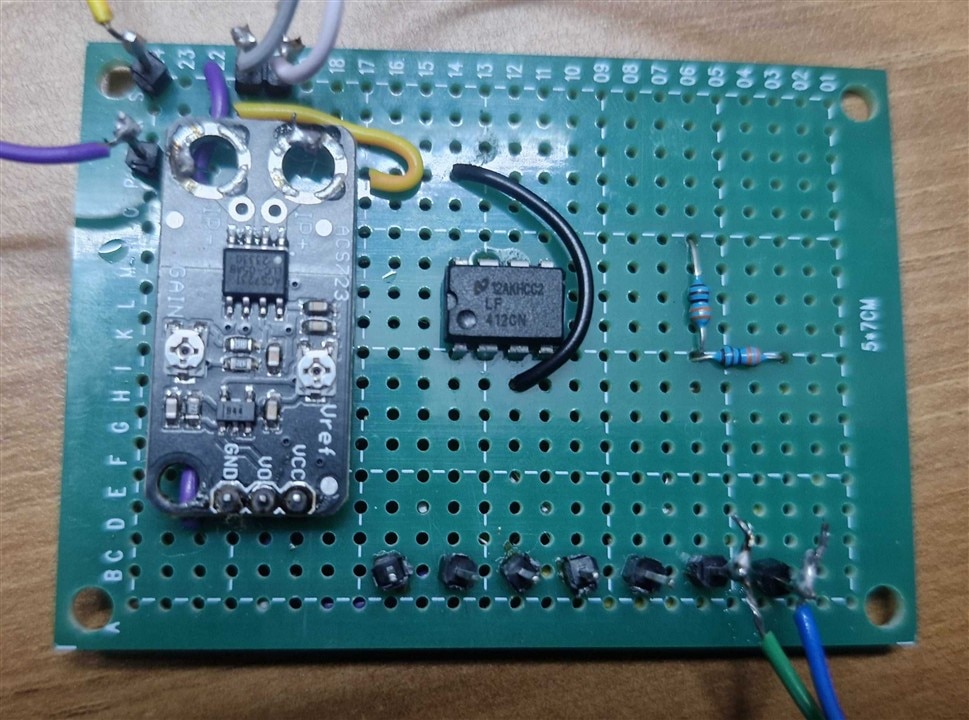
For the first hardware prototype, I assembled the voltage, current and temperature measurement circuits on a veroboard.
The three analogue measurements are connected to the Arduino UNO Q as follows:
| Arduino UNO Q | Measurement |
|---|---|
| A0 | Battery Current |
| A1 | Battery Voltage |
| A2 | Battery Temperature |
This keeps the measurement interface simple and gives me a clear separation between the three primary battery parameters.
1. Battery Voltage Measurement
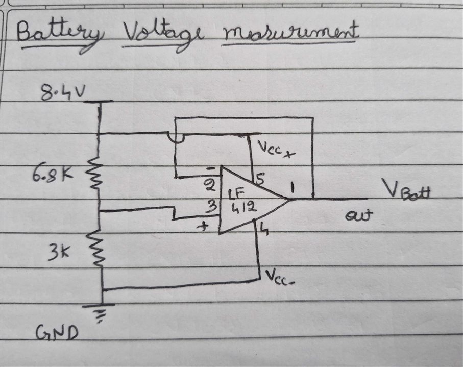
The battery pack can reach 8.4 V, which is higher than the Arduino UNO Q's analogue input range. Therefore, I cannot directly connect the battery voltage to the ADC. I used a 6.8 kΩ and 3 kΩ resistor voltage divider to scale the battery voltage down to a suitable level for measurement. The divided voltage is then passed through an LF412 op-amp configured as a buffer before being connected to the Arduino UNO Q. The buffer provides a high-impedance interface between the voltage divider and the ADC, helping prevent the ADC input from significantly loading the divider.
The scaled voltage is connected to:
Arduino UNO Q → A1
The software then converts the measured ADC voltage back into the actual battery voltage using the calibrated divider ratio. This gives me the first fundamental parameter required for battery profiling.
2. Current Measurement Using ACS723
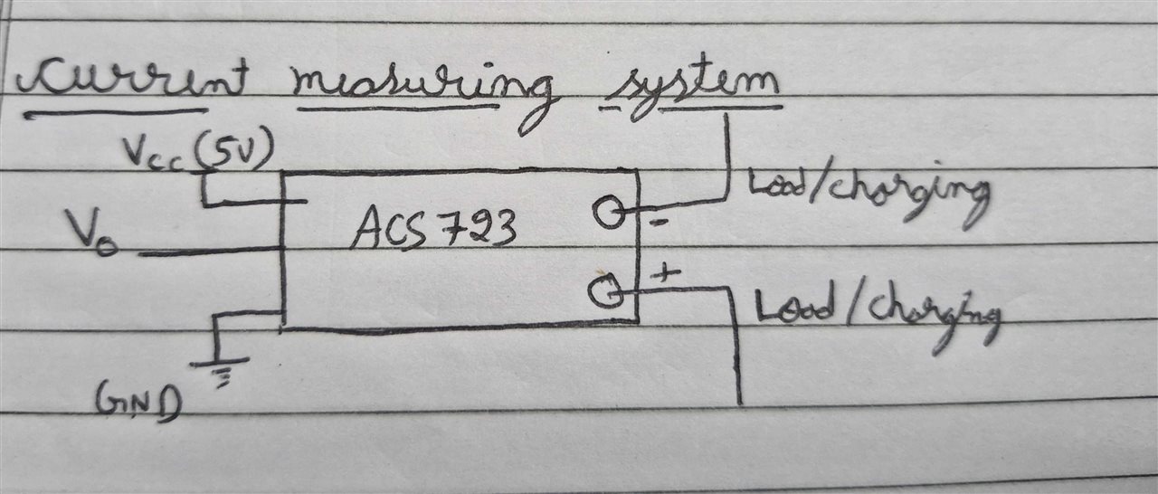
The second important parameter is battery current. For this, I am using the ACS723 current sensor.The sensor provides an analogue output proportional to the current flowing through it. For my setup, the sensor output is approximately 1.70 V at zero current, which becomes the reference or zero-current point. The current sensitivity used in my implementation is approximately 1.336 V/A.
Therefore, the Arduino UNO Q measures the ACS723 output through:
A0 → ACS723 Current Sensor
The software then uses the calibrated zero-current offset and sensitivity to determine the actual battery current.
This allows the system to determine whether the battery is:
- Charging
- Discharging
- Idle
and also provides the current value required for power and energy calculations.
3. Battery Temperature Measurement
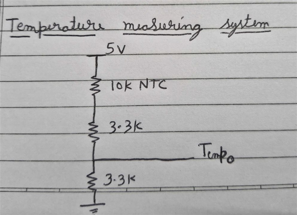
Temperature is another critical parameter for a Li-ion battery. For the prototype, I am using a 10 kΩ NTC thermistor attached to the battery module. The thermistor is combined with resistor networks to generate a temperature-dependent voltage that can be measured by the Arduino UNO Q.
The midpoint of the resistor network is connected to:
Arduino UNO Q → A2
As the battery temperature changes, the resistance of the NTC changes, which produces a corresponding change in the measured voltage. The software can then convert this ADC measurement into an estimated battery temperature. Monitoring temperature becomes particularly important when analysing high-current charging and discharging conditions.
Bringing Voltage, Current and Temperature Together
Individually, voltage, current and temperature provide useful information. But the real value comes from looking at all three together.
The Arduino UNO Q continuously acquires:
Voltage + Current + Temperature
From these measurements, I can calculate additional battery parameters such as:
- Battery power
- Charging/discharging state
- Energy consumption
- Open-circuit voltage
- State of Charge
- State of Health
- Battery operating conditions
This is where the project begins moving from a simple battery monitoring system toward a battery profiling and intelligence system.
Estimating State of Charge
Determining the exact state of charge (SOC) of a battery pack isn't as simple as checking a voltage level. If you only look at voltage, it sags significantly when you draw a load (discharging) and rises when you apply a charger. To solve this, our Battery Management System (BMS) uses a Hybrid SOC Algorithm combining Coulomb Counting and Open-Circuit Voltage (OCV) Recalibration.
Here is how the algorithm works:
1. Real-Time Tracking: Coulomb Counting
During active operation, the BMS tracks the flow of current in and out of the battery second-by-second.
- The Math: Capacity (Ah) = Current (A) * Time (hours)
- Charge Efficiency: When discharging (negative current), energy is drawn directly. When charging (positive current), a 98% Coulombic efficiency multiplier is applied to account for chemical and thermal losses during charge conversion.
- The Benefit: It responds instantly to sudden load changes and updates the SOC in real-time, regardless of voltage sags.
2. Auto-Calibration: OCV Lookup Table + Rest Timer
Over time, current sensors accumulate tiny measurement errors (drift), which causes Coulomb counting to become inaccurate. To correct this drift, I use an OCV Lookup Table (LUT) containing the chemistry's non-linear voltage-to-capacity curve.
However, voltage is only a true representation of SOC when the battery chemistry has relaxed (neutralized).
- The Rest Timer: The BMS continuously checks if the battery is "at rest" (current < 50mA).
- The Relaxation Window: Once the battery remains at rest for 60 continuous seconds, the algorithm trusts the voltage reading.
- Recalibration: The OCV lookup table calculates the true chemical SOC, and the Coulomb counter (
accumulatedAh) is calibrated back to this exact value, erasing any accumulated sensor drift.
3. Smart Boot Synchronization
Since SOC is volatile, standard systems often write the SOC to EEPROM constantly, causing premature flash wear.
Our hybrid algorithm solves this by only saving long-term health parameters (SOH and Cycle count) to EEPROM. When the system powers up:
- It waits for the power rail to stabilize.
- It takes an averaged, direct voltage measurement.
- It snaps the Coulomb counter to match this OCV reading on boot.
This guarantees the system never boots up showing a stale or incorrect 0% SOC even if you swap in a different pack.
Energy and Coulomb Tracking
Current measurement also allows me to track the amount of charge flowing into and out of the battery.By integrating current over time, I can estimate the accumulated charge in coulombs or ampere-hours. Combining current with voltage also allows the system to calculate instantaneous power and accumulated energy.
This information will eventually help me understand:
- How much energy the battery delivers
- How much energy is consumed by the load
- Charging energy
- Discharging energy
- Battery efficiency
These measurements will also provide useful data for the battery profiling stage.
Battery State of Health
SoC tells me:
How much charge is available right now?
But SoH asks a different question:
How healthy is the battery compared with when it was new?
For this project, I want to use the data collected during repeated charging and discharging cycles to study battery degradation.
Parameters such as:
- Available capacity
- Charge/discharge behaviour
- Voltage response
- Temperature behaviour
- Current profile
- Cycle count
can be analysed to estimate battery health.
This will eventually become one of the more interesting parts of the Battery Management Node, where I plan to explore data-driven and ML-based battery health estimation.
Using the Arduino UNO Q LED Matrix
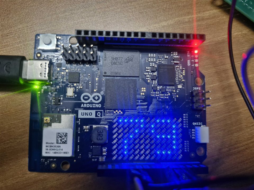
I also wanted to make the battery information visible without requiring a laptop. The Arduino UNO Q provides an onboard LED matrix, so I decided to use it to display the current State of Charge percentage.
For example:
75%
can be displayed directly on the LED matrix. As the battery is discharged, the displayed value updates accordingly. This provides a simple visual indication of battery status and also makes the system much more engaging during a live demonstration.
Software Architecture
The Arduino UNO Q continuously performs the following sequence:
Read ADC → Convert to Physical Value → Filter/Calibrate → Calculate Battery Parameters → Update LED Matrix → Update Telemetry
The three ADC channels are sampled periodically:
A0 → Current
A1 → Battery Voltage
A2 → Temperature
The raw ADC values are then converted into meaningful engineering units using the calibration parameters of each sensor. The processed values can then be used for the higher-level battery calculations.
Code Implementation
The software is being developed in stages, starting with reliable sensor acquisition and calibration before moving towards the battery intelligence layer.
Some of the important parts of the implementation include:
- ADC acquisition
- ACS723 current calculation
- Battery voltage calculation
- NTC temperature calculation
- SoC estimation
- Coulomb counting
- Power and energy calculation
- Battery status monitoring
- LED matrix SoC display
// Force high-resolution ADC in setup()
analogReadResolution(14);

// Exponential Moving Average filter configuration
const float FILTER_ALPHA = 0.1f;
bool isFirstRead = true;

void readSensors() {
  // Read raw inputs
  float rawCurrent = readACS723Current();
  float rawVoltage = readVoltageDivider();
  float rawTemp    = readNTCTemperature();

  // Smooth signals using EMA Filter
  if (isFirstRead) {
    systemCurrent     = rawCurrent;
    systemVoltage     = rawVoltage;
    systemTemperature = rawTemp;
    isFirstRead       = false;
  } else {
    systemCurrent     = FILTER_ALPHA * rawCurrent + (1.0f - FILTER_ALPHA) * systemCurrent;
    systemVoltage     = FILTER_ALPHA * rawVoltage + (1.0f - FILTER_ALPHA) * systemVoltage;
    if (rawTemp > -900.0f) {
      systemTemperature = FILTER_ALPHA * rawTemp + (1.0f - FILTER_ALPHA) * systemTemperature;
    }
  }
}
This snippet shows the sensor acquisition routine configured for high-precision 14-bit ADC resolution (0 - 16383 counts) and smoothed using an Exponential Moving Average (EMA) filter to filter out switching noise
// Configuration parameters
const float CURRENT_ZERO_POINT_V       = 1.70f;  // Mid-point offset (V)
const float CURRENT_SENSITIVITY_V_PER_A = 1.336f; // V/A sensitivity

// Conversion logic
int   currentADC  = analogRead(CURRENT_PIN);
float currentPinV = ((float)currentADC / ADC_MAX_VALUE) * ADC_REF_VOLTAGE;

// Calculate current (negative = discharge/load, positive = charging)
float rawCurrent  = (currentPinV - CURRENT_ZERO_POINT_V) / CURRENT_SENSITIVITY_V_PER_A;
The current is calculated using an ACS723 Hall-Effect sensor. Negative current denotes discharge (load connected), and positive current denotes charging
// Configuration parameters (6.8K and 3K resistors)
const float R1_VOLTAGE_DIVIDER = 6800.0f;
const float R2_VOLTAGE_DIVIDER = 3000.0f;
const float VOLTAGE_MULTIPLIER = (R1_VOLTAGE_DIVIDER + R2_VOLTAGE_DIVIDER) / R2_VOLTAGE_DIVIDER;

// Conversion logic
int   voltageADC  = analogRead(VOLTAGE_PIN);
float voltagePinV = ((float)voltageADC / ADC_MAX_VALUE) * ADC_REF_VOLTAGE;

// Scaling to calculate full pack voltage
float rawVoltage  = voltagePinV * VOLTAGE_MULTIPLIER;
The total battery voltage is calculated by scaling the voltage at the divider pin back to the full pack voltage using the calculated scaling multiplier.
// Configuration parameters
const float NTC_VCC                = 5.0f;
const float NTC_R_FIXED            = 3300.0f;
const float NTC_R_SERIES           = 3300.0f;
const float NTC_NOMINAL_RESISTANCE = 10000.0f;
const float NTC_NOMINAL_TEMP       = 298.15f; // 25 C
const float NTC_BETA               = 3950.0f;

// Steinhart-Hart conversion logic
int   tempADC   = analogRead(TEMP_PIN);
float tempPinV  = ((float)tempADC / ADC_MAX_VALUE) * ADC_REF_VOLTAGE;
float rawTemp   = -999.0f;

if (tempPinV > 0.01f) {
  float rNTC    = (NTC_VCC * NTC_R_FIXED / tempPinV) - (NTC_R_FIXED + NTC_R_SERIES);
  if (rNTC > 0.0f) {
    float s = log(rNTC / NTC_NOMINAL_RESISTANCE);
    s = (s / NTC_BETA) + (1.0f / NTC_NOMINAL_TEMP);
    rawTemp = (1.0f / s) - 273.15f; // Kelvin to Celsius conversion
  }
}
The thermistor temperature is processed using the Steinhart-Hart equation to convert NTC resistance changes into Degrees Celsius
// 1. Coulomb Counter integration (runs every 100ms)
void integrateCoulombs(unsigned long timeDeltaMs) {
  float dt_hours = (float)timeDeltaMs / 3600000.0f;

  if (systemCurrent > 0.0f) {
    // Charging: apply coulombic efficiency (98%)
    accumulatedAh += systemCurrent * CHARGE_EFFICIENCY * dt_hours;
  } else {
    // Discharging: subtract directly
    accumulatedAh += systemCurrent * dt_hours;
  }

  // Hard clamp accumulated capacity inside limits
  if (accumulatedAh > persistentState.actualMaxCapacityAh) accumulatedAh = persistentState.actualMaxCapacityAh;
  if (accumulatedAh < 0.0f) accumulatedAh = 0.0f;
}

// 2. Hybrid OCV Calibration and SOC calculation
void calculateSOC() {
  bool isAtRest = (fabs(systemCurrent) < REST_CURRENT_THRESHOLD_A);

  if (isAtRest) {
    rest_timer_ms += READ_INTERVAL_MS;
  } else {
    rest_timer_ms = 0; // Current flow resets the rest timer
  }

  // Recalibration: only trust OCV when battery has rested (60 seconds)
  if (rest_timer_ms >= REST_DURATION_MS) {
    float ocvSOC = get_soc_from_ocv(systemVoltage);
    accumulatedAh = (ocvSOC / 100.0f) * persistentState.actualMaxCapacityAh;
    rest_timer_ms = 0; // Reset calibration trigger
    Serial.println("Coulomb counter recalibrated using resting OCV.");
  }

  // Calculate final system SOC
  systemSOC = (accumulatedAh / persistentState.actualMaxCapacityAh) * 100.0f;
  if (systemSOC > 100.0f) systemSOC = 100.0f;
  if (systemSOC <   0.0f) systemSOC =   0.0f;
}
This snippet integrates Coulomb counting during current flow (applying charging efficiency) and runs the rest-timer OCV recalibration when the battery relaxes.
void render_soc(float soc) {
  // Convert float SOC to rounded 2-digit integer
  int soc_int = (int)(soc + 0.5f);
  if (soc_int > 99) soc_int = 99;
  if (soc_int < 0) soc_int = 0;

  // Lock buffer to prevent race conditions during rendering
  k_mutex_lock(&matrix_mtx, K_FOREVER);
  clear_matrix_buf();

  if (soc_int >= 10) {
    int tens = soc_int / 10;
    int units = soc_int % 10;
    render_digit(tens, 1, 7);  // Left digit (cols 1-5)
    render_digit(units, 7, 7); // Right digit (cols 7-11)
  } else {
    render_digit(soc_int, 4, 7); // Center single digit (cols 4-8)
  }

  flush_matrix_locked(); // Output buffer to Arduino LED matrix hardware
  k_mutex_unlock(&matrix_mtx);
}
This snippet shows how a custom pixel font renders the SOC integers, safely locked behind Zephyr RTOS mutexes to ensure thread safety while writing to the matrix buffer.
From Battery Monitoring to Battery Intelligence
At this stage, the system can measure the three most important physical parameters:
Voltage → Current → Temperature
But this is only the beginning. The ultimate goal of this Battery Management Node is not simply to display these values.
I want the system to understand what these measurements mean.
For example, instead of simply showing:
Temperature = 42°C
the system should eventually be able to determine:
️ Battery temperature is increasing faster than expected.
Instead of only displaying:
SoH = 78%
the system could eventually provide:
Similarly, abnormal combinations of voltage, current and temperature could be used to identify potential battery anomalies. This is where the collected battery data will become extremely valuable for battery profiling and predictive maintenance features planned for EVA Guardian.
Testing the Battery Management System
The next stage is to systematically test the measurement system under different operating conditions.
I plan to test the battery during:
- Charging
- Idle/resting
- Low-current discharge
- High-current discharge
- Different temperature conditions
- Different SoC levels
The goal is to compare the measured values against reference measurements and calibrate the system before using the data.Therefore, the initial focus is on making sure that the voltage, current and temperature measurements are reliable and repeatable.
Demonstration Video
I have also recorded a demonstration of the Battery Management Node showing the hardware setup, sensor measurements and real-time SoC display on the Arduino UNO Q LED matrix.
What's Next?
With the basic Battery Management Node now assembled, the next stage of EVA Guardian is to bring the individual modules together into a complete safety and monitoring system. The first step will be to integrate the Battery Management System (BMS) and Incident Detection System (IDS) so that battery information and vehicle safety information can be monitored together.
The integrated system will focus on:
- Battery voltage, current and temperature monitoring
- SoC and battery operating status
- Overvoltage, undervoltage and overcurrent protection
- Vehicle motion and incident detection
- Accident detection
- Distance and trip information
- Real-time system status
I will also be implementing a safety relay and automatic power switching mechanism. The objective is to allow the system to respond to critical conditions by automatically controlling the battery/load power path. A backup power source will also be incorporated to keep essential functions such as the safety controller and emergency communication operational when required.
Finally, I will bring all the information together through a web-based interface, providing a single dashboard for monitoring both the battery and vehicle safety systems.
The overall system will therefore evolve from two independent prototypes into a connected platform:
Battery Management + Incident Detection → Safety Control → Automatic Power Management → Web Monitoring
The next phase will focus on this system-level integration and demonstrating how EVA Guardian can continuously monitor the EV, detect abnormal conditions, take appropriate safety action, and provide the user with a clear view of the vehicle's overall health and safety status.