


This is a final blog post for Light Up Your Life design challenge with Element14 and Würth Elektronik. The design challenge was about creating LED lights using Würth Elektronik programmable SMD LEDs. Hence anything that can be in the following category could be a design idea.
- Smart LED Lights for home/office
- Decorative Lights
- LED based art
- Smart greenhouse for agriculture
- Any instruments that need different colored light
Light Up Your Life design challenge has official kit that includes some parts that are needed for the build. In my project, I have tried to use as much of the parts that are suggested by the challenge.
Table of Contents
Overview
For this challenge, I have created five forum posts. In that, I have discussed from start till the end of the project. I have discussed about selecting different kinds of LEDs and reading different parameters for the LEDs such as current and power requirements of these LEDs in the first blog. Then creating of schematic design in KiCad in the second blog. In the third blog I have posted about working prototype of the PCB that I received. The fourth one discusses about the ESP-NOW protocol to control the LEDs using wireless communication. Then in the firth post, I have discussed about BLE and how to change and set different color values for LEDs using Bluetooth. Also in the same blog I have discussed about adding different effects to the LEDs to make it more decorative and attractive.
Post-5 RGBMATRIX enabling BLE to change light color and adding effects - Blog-5 - element14 Community
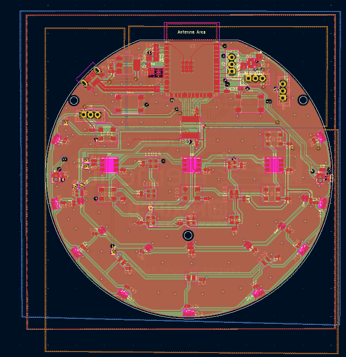
PCB design
For the PCB design I have used KiCAD. I have used ESP32-S3 Wroom based design. This design has ESP32s3 chip with 16-MB flash memory. The module has inbuilt antenna and support for Bluetooth and WiFi communication. For details of schematic and detailed design you can look at Blog 1 for more in-depth information.
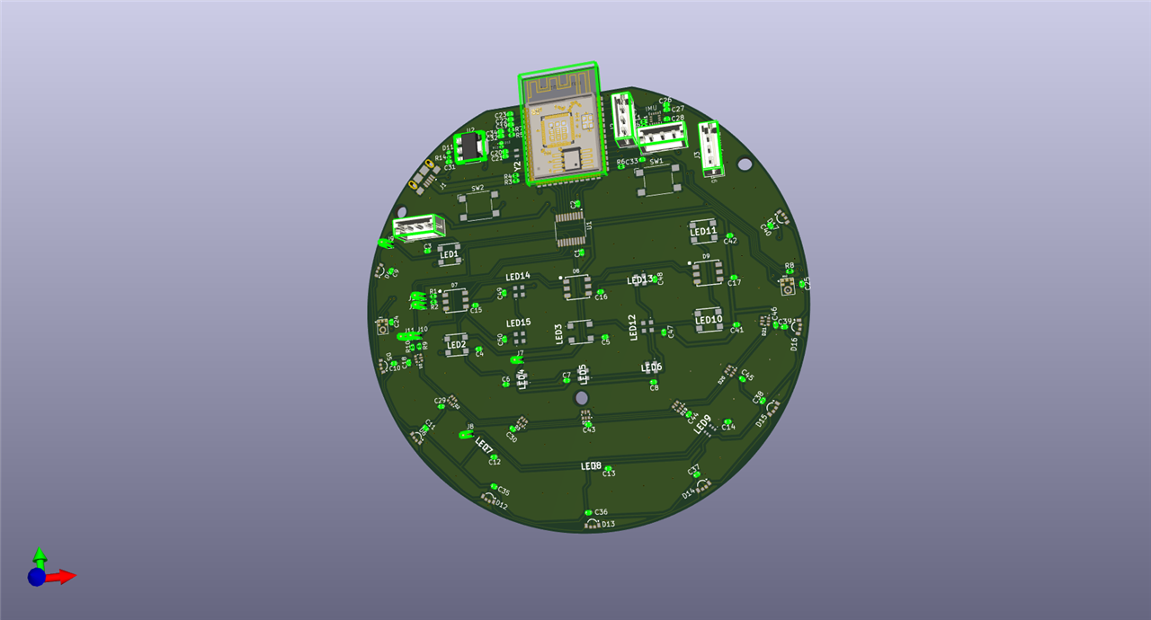
LEDs
I have use five different kinds of LEDs. These were suggested by the sponsored kit. In addition to that I have used Texas instruments level converter (TXS0108EPWR) for voltage conversion from 3.3V to 5V that nicely fits into the design.
- 1313210530000 (9-leds on the corner) (19.5mA each)
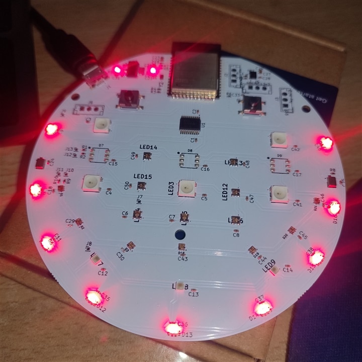
- 1312121320437 (3-leds) (23x3 = 69mA each) (SPI Interface)
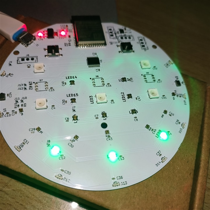
- 1311610030140 (7-leds) (17.5 mA each) (SPI interface)
- 1315050930002 (5-leds) (14.5x3 = 43.5mA each)
- 1312020030000 (7-leds) (6.5x3 = 20.5mA each)
ESP-NOW
ESP-NOW is a connectionless wireless protocol. Means it does not need to follow complex connection process that is included with other protocols such as WiFi and BLE. Also, the ESP-NOW supports quite long range compared to Bluetooth and WiFi. It can operate up to a range of 220 meters. I have shown simple ESP-NOW application in Blog-4.
For this final project, I have created a simple Keypad based test application to evaluate ESP-NOW and its application in smart light applications. I have created two nodes. One can send the keypress values, and another can change the color based on the key press. I am using Arduino code for the sender and Micropython on the receiver end. I have enabled the Long-Range mode to test the communication range.
I also tested the communication range and it's well beyond 100 meters in open space.
#include <Keypad.h>
#include "WiFi.h"
#include <esp_now.h>
#include <esp_wifi.h>

uint8_t val;
esp_err_t result;

const byte ROWS = 4;
const byte COLS = 4;

char keys[ROWS][COLS]  {
  { '1', '2', '3', 'A' },
  { '4', '5', '6', 'B' },
  { '7', '8', '9', 'C' },
  { '*', '0', '#', 'D' }
};

byte rawPins[ROWS] = {8, 7, 6, 5};
byte colPins[COLS] = {4, 3, 2, 1};

Keypad keypad = Keypad(makeKeymap(keys), rawPins, colPins, ROWS, COLS);

//espnow related defines
uint8_t receiver_addr[] = {0x10, 0x20, 0xBA, 0x59, 0x7A, 0xC8};
esp_now_peer_info_t peerInfo;

//send callback
void OnDataSent(const uint8_t *mac_addr, esp_now_send_status_t status) {
  Serial.print("\r\nLast Packet Send Status:\t");
  Serial.println(status == ESP_NOW_SEND_SUCCESS ? "Delivery Success" : "Delivery Fail");
}

void setup() {
  // put your setup code here, to run once:
  Serial.begin(115200);

  // Set device as a Wi-Fi Station
  WiFi.mode(WIFI_MODE_STA);
  esp_wifi_set_protocol( WIFI_IF_STA , WIFI_PROTOCOL_LR);

  // Init ESP-NOW
  if (esp_now_init() != ESP_OK) {
    Serial.println("Error initializing ESP-NOW");
    return;
  }

  //send callback
  esp_now_register_send_cb(esp_now_send_cb_t(OnDataSent));

  memcpy(peerInfo.peer_addr, receiver_addr, 6);
  peerInfo.channel = 0;
  peerInfo.encrypt = false;

  if(esp_now_add_peer(&peerInfo) != ESP_OK) {
    Serial.println("Failed to add peer");
    return;
  }
}

void loop() {
  // put your main code here, to run repeatedly:
  char key = keypad.getKey();
  if(key) {
    Serial.println("Key Pressed : ");
    Serial.println(key);
    val = (int)key;

    switch (val) {
    //2 pressed
      case 50:
        result = esp_now_send(receiver_addr, (uint8_t *) &val, sizeof(val));

        if (result == ESP_OK) {
          Serial.println("Sent with success");
        }
        else {
          Serial.println("Error sending the data");
        }
        break;

      case 51:
        result = esp_now_send(receiver_addr, (uint8_t *) &val, sizeof(val));

        if (result == ESP_OK) {
          Serial.println("Sent with success");
        }
        else {
          Serial.println("Error sending the data");
        }
        break;
      case 53:
        result = esp_now_send(receiver_addr, (uint8_t *) &val, sizeof(val));

        if (result == ESP_OK) {
          Serial.println("Sent with success");
        }
        else {
          Serial.println("Error sending the data");
        }
        break;
        case 54:
        result = esp_now_send(receiver_addr, (uint8_t *) &val, sizeof(val));

        if (result == ESP_OK) {
          Serial.println("Sent with success");
        }
        else {
          Serial.println("Error sending the data");
        }
        break;
        case 56:
        result = esp_now_send(receiver_addr, (uint8_t *) &val, sizeof(val));

        if (result == ESP_OK) {
          Serial.println("Sent with success");
        }
        else {
          Serial.println("Error sending the data");
        }
        break;
        case 57:
        result = esp_now_send(receiver_addr, (uint8_t *) &val, sizeof(val));

        if (result == ESP_OK) {
          Serial.println("Sent with success");
        }
        else {
          Serial.println("Error sending the data");
        }
        break;
        case 48:
        result = esp_now_send(receiver_addr, (uint8_t *) &val, sizeof(val));

        if (result == ESP_OK) {
          Serial.println("Sent with success");
        }
        else {
          Serial.println("Error sending the data");
        }
        break;
        case 65:
        result = esp_now_send(receiver_addr, (uint8_t *) &val, sizeof(val));

        if (result == ESP_OK) {
          Serial.println("Sent with success");
        }
        else {
          Serial.println("Error sending the data");
        }
        break;
        case 66:
        result = esp_now_send(receiver_addr, (uint8_t *) &val, sizeof(val));

        if (result == ESP_OK) {
          Serial.println("Sent with success");
        }
        else {
          Serial.println("Error sending the data");
        }
        break;
        case 67:
        result = esp_now_send(receiver_addr, (uint8_t *) &val, sizeof(val));

        if (result == ESP_OK) {
          Serial.println("Sent with success");
        }
        else {
          Serial.println("Error sending the data");
        }
        break;
        case 68:
        result = esp_now_send(receiver_addr, (uint8_t *) &val, sizeof(val));

        if (result == ESP_OK) {
          Serial.println("Sent with success");
        }
        else {
          Serial.println("Error sending the data");
        }
        break;
    }
    Serial.println(val);
  }
}
import time
import machine, network
import espnow
import ubinascii
import neopixel

receiver = network.WLAN(network.WLAN.IF_STA)
receiver.active(True)
receiver.config(protocol=network.MODE_LR)

mac_bytes = receiver.config('mac')
mac_address = ubinascii.hexlify(mac_bytes, ':').decode().upper()
print(mac_address)

espnow = espnow.ESPNow()
espnow.active(True)

sender = b'\x7C\xDF\xA1\x07\xBE\xA6'
espnow.add_peer(sender)

ledcorner = machine.Pin(12)
ledfive = machine.Pin(45)
ledseven = machine.Pin(47)

neopixelcorner = neopixel.NeoPixel(ledcorner, 9)
neopixelfive = neopixel.NeoPixel(ledfive, 5)
neopixelseven = neopixel.NeoPixel(ledseven, 7)

red = 255
green = 0
blue = 0

def set_color(red, green, blue):
    for i in range(9):
        neopixelcorner[i] = (red, green, blue)
    for i in range(5):
        neopixelfive[i] = (red, green, blue)
    for i in range(7):
        neopixelseven[i] = (red, green, blue)

    neopixelcorner.write()
    neopixelfive.write()
    neopixelseven.write()

while(1):
    mac, msg = espnow.recv()
    if(msg):
        print('msg received')
        print(msg)
        if(msg == b'2'):
            set_color(255, 255, 255)
        if(msg == b'3'):
            set_color(255, 0, 0)
        if(msg == b'5'):
            set_color(255, 255, 0)
        if(msg == b'6'):
            set_color(0, 255, 0)
        if(msg == b'8'):
            set_color(0, 255, 255)
        if(msg == b'9'):
            set_color(0, 0, 255)
        if(msg == b'0'):
            set_color(0, 0, 0)
        if(msg == b'A'):
            set_color(255, 0, 255)
        if(msg == b'B'):
            set_color(255, 50, 50)
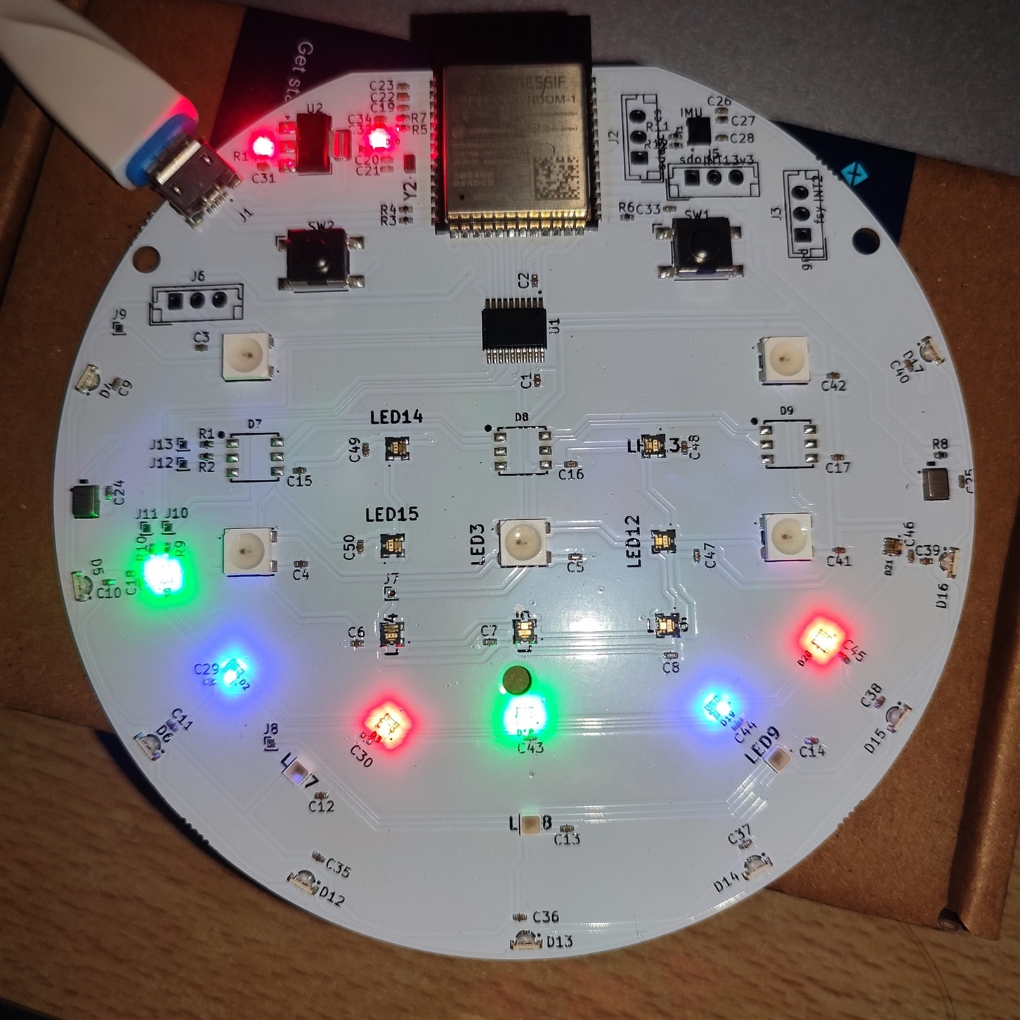
Bluetooth based Light control
Controlling smart light using Bluetooth communication is one of the important features that we see often. The advantage of using Bluetooth is that it is supported by most smartphones. So, one can use Android or Apple smartphone applications to control the smart light and its colors. It also has other advantages such as robust connection and advanced security features.
I have discussed BLE based light control in post-5 in detail, but I will also explain it here.
For Bluetooth based light control one can use BLE communication. BLE can have Services and Characteristics that can be accessed by remote user using another BLE device such as a smartphone with Android application.
Here is a simple application in Micropython using BLE module and a demo video that shows I how to change the color of the LED using smartphone or PC with BLE.
import time
import bluetooth
from bluetooth import BLE

import asyncio
import ubinascii
import neopixel
import machine
from micropython import const
import esp32

import network

_IRQ_CENTRAL_CONNECT = const(1)
_IRQ_CENTRAL_DISCONNECT = const(2)
_IRQ_GATTS_WRITE = const(3)
_IRQ_GATTS_READ_REQUEST = const(4)

_IRQ_GATTC_READ_RESULT = const(15)
_IRQ_GATTC_READ_DONE = const(16)
_IRQ_GATTC_WRITE_DONE = const(17)

nvs = esp32.NVS("RGBMAT")

try:
    status = nvs.get_i32("Lighton")
except OSError:
    print('Blob is not set, setting it now..')
    nvs.set_i32("Lighton", 1)
    nvs.set_i32("red" , 255)
    nvs.set_i32("blue" , 0)
    nvs.set_i32("green" , 0)
    nvs.commit()

ledcorner = machine.Pin(12)
ledfive = machine.Pin(45)
ledseven = machine.Pin(47)

neopixelcorner = neopixel.NeoPixel(ledcorner, 9)
neopixelfive = neopixel.NeoPixel(ledfive, 5)
neopixelseven = neopixel.NeoPixel(ledseven, 7)

class RGBMATRIX():
    def __init__(self, name):
        self.name = name
        self.BLE = bluetooth.BLE()
        self.BLE.active(True)
        self.connection = set()
        self.register_services()
        self.BLE.irq(self.ble_irq)
        self.advertise()

        self.redl = nvs.get_i32("red")
        self.bluel = nvs.get_i32("blue")
        self.greenl = nvs.get_i32("green")

        self.set_led_strip(self.redl.to_bytes(1), self.bluel.to_bytes(1), self.greenl.to_bytes(1))

    def register_services(self):
        RGB_UUID = bluetooth.UUID('7bf20ec6-e66f-4a61-9aa4-8fa20097a0c4')

        RED_UUID = (bluetooth.UUID('7bf20ec6-e66f-4a61-9aa4-8fa20097a0c5'), bluetooth.FLAG_READ | bluetooth.FLAG_WRITE,)
        BLUE_UUID = (bluetooth.UUID('7bf20ec6-e66f-4a61-9aa4-8fa20097a0c6'), bluetooth.FLAG_READ | bluetooth.FLAG_WRITE,)
        GREEN_UUID = (bluetooth.UUID('7bf20ec6-e66f-4a61-9aa4-8fa20097a0c7'), bluetooth.FLAG_READ | bluetooth.FLAG_WRITE,)

        rgb_service = (RGB_UUID, (RED_UUID, BLUE_UUID, GREEN_UUID,),)
        services = (rgb_service,)
        ( (self.red, self.green, self.blue,), ) = self.BLE.gatts_register_services(services)

    def advertise(self):

        name = bytes(self.name, 'UTF-8')
        advdata = bytearray(b'\x02\x01\x02') + bytearray((len(name) + 1, 0x09)) +  name
        self.BLE.gap_advertise(100, advdata)
         #get MAC address
        mac = self.BLE.config('mac')[1]
        print("device MAC address is: "+ubinascii.hexlify(mac).decode())

    def ble_irq(self, event, data):

        if event == _IRQ_CENTRAL_CONNECT:
            conn_handle, addr_type, addr = data
            self.connection.add(conn_handle)
            print('Central connected')

        elif event == _IRQ_CENTRAL_DISCONNECT:
            conn_handle, addr_type, addr = data
            self.connection.remove(conn_handle)
            self.advertise()
            print('Central disconnected.')

        elif event == _IRQ_GATTS_WRITE:
            conn_handle, attrb_handle = data
            #print('Gatts write')
            self.val_red = self.BLE.gatts_read(self.red)
            self.val_blue = self.BLE.gatts_read(self.blue)
            self.val_green = self.BLE.gatts_read(self.green)
            self.set_led_strip(self.val_red, self.val_blue, self.val_green)

        elif event == _IRQ_GATTS_READ_REQUEST:
            conn_handle, attrb_handle = data
            #print('read request')

    def set_led_strip(self, red, blue, green):

        for i in range(9):
            neopixelcorner[i] = (int.from_bytes(red), int.from_bytes(blue), int.from_bytes(green))

        for i in range(5):
            neopixelfive[i] = (int.from_bytes(red), int.from_bytes(blue), int.from_bytes(green))

        for i in range(7):
            neopixelseven[i] = (int.from_bytes(red), int.from_bytes(blue), int.from_bytes(green))

        neopixelcorner.write()
        neopixelfive.write()
        neopixelseven.write()

        nvs.set_i32("red" , int.from_bytes(red))
        nvs.set_i32("blue" , int.from_bytes(blue))
        nvs.set_i32("green" , int.from_bytes(green))

def main():
    BLE = RGBMATRIX("ESP32S3")
    #BLE.set_color(255)

if __name__ == "__main__":
    main()
Machine Learning models
Machine Learning is one of the important features that one could add to the project. There are many different possibilities. When I started to design the PCB, I realized this fact that adding some sensors such as Microphone, IMU and others can help create a smart device that can run machine learning models. Adding some tiny camera could have been an option but it was not feasible due to availability of number of GPIOs and also running vision-based ML model takes lots of memory and compute resources such as RAM for these tiny microcontroller devices.
But fortunately, ESP32 based device can run a tiny model and some other peripherals such as LED lights and sensors. Or it can run vision-based model alone. That would be a good design choice. Also, thanks to optimization of various ML model libraries to fit into tiny microcontrollers so that one can run ML models.
In this PCB, I have two (stereo) microphones and one IMU sensor that can detect movements and motion-based gestures. Microphone can be used to run a model that can detect keywords such as "Light ON" or "Light OFF" and IMU sensor can detect movements such as "circle", "wave", etc.
Vision based models
To add vision-based ML model there are a couple of options. One thing is final that I have to use external camera device to run the model and detect objects. I can use anything similar to ESP32-CAM, Nicla Vision AI, Grove vision AI or even a Raspberry Pi to run these models. I can send final inference value to the LED device over some wired or wireless protocols. Both can work. For wired one, I can use I2C, Onewire or even some pulse counting method to send data. But that would be trivial in my case. Also using wireless protocol would make sense for remotely operating the device. For wireless options I can use ESP-NOW, BLE or Socket connection over local network to send the data.
For training and creating the model, I also have some options here. I can use Edge Impulse Studio, Roboflow, Ultralytics YOLO, Sensiml, etc to do the model training. I can then download and run the model on the Edge device.
- Using Seeed Grove Vision AI module
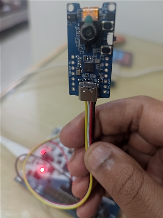
Seeed Studio Grove vision AI module can run Edge Impulse models. It is also officially supported by the Edge Impulse. The trained model than can be downloaded to the device over USB and can run in real time. I will explain the steps that are needed to create and run this model on to the device.
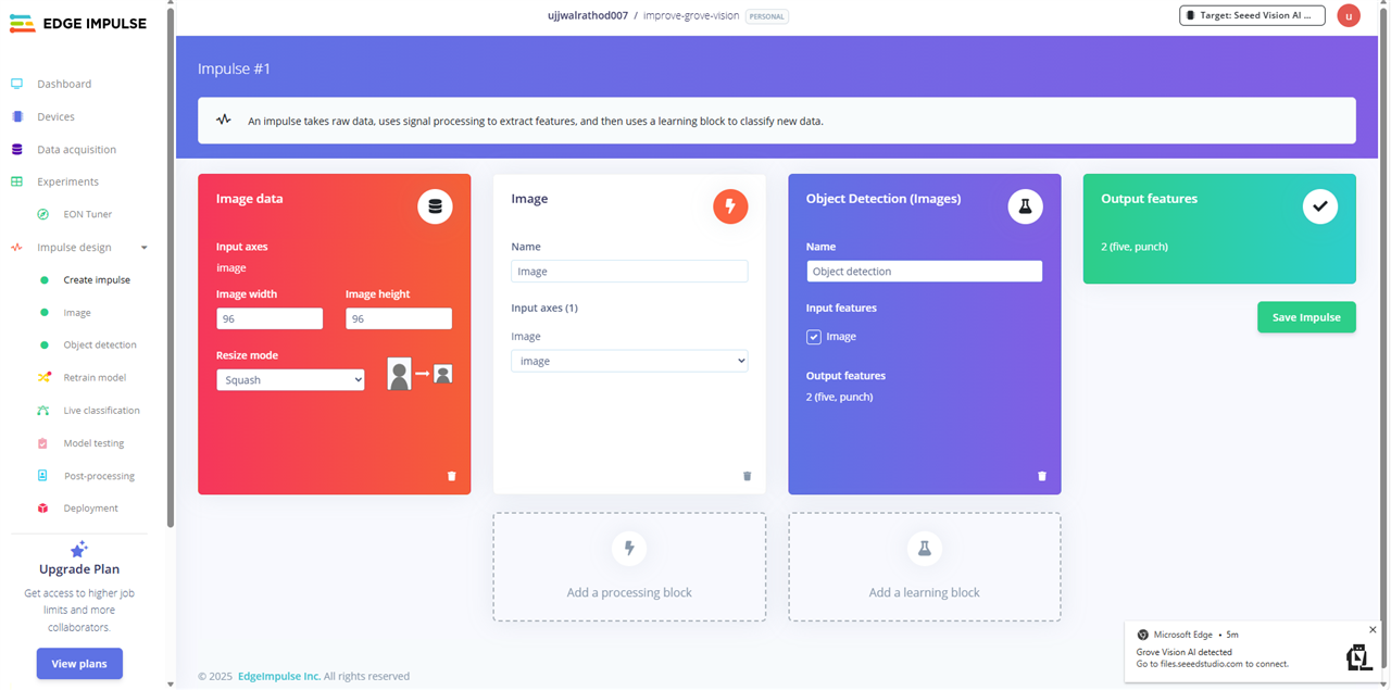
The first step is to collect the require data for training of the model. To collect the data, it is advisable to use the same device that we are going to run the inference on. Grove vision AI can be used to collect the image data required for gesture detection. The Edge Impulse docs have the required firmware to be downloaded on to the device. Once downloaded the device will be connected to the Edge Impulse studio and image data can be uploaded over USB using Web browser.
Once the model training is finished as shown in the above video, one can upload the following sketch to the device and see the detection results. For this connect the Grove module to the I2C port of the device. For that, I am using ESP32s2 based device. I am also using ESP-NOW to send the detection result to the device with LED lights. In combination this device will act as gesture based remote control to change LED brightness.
#include <Wire.h>
#include "Seeed_Arduino_GroveAI.h"
#include "WiFi.h"
#include <esp_now.h>

GroveAI ai(Wire);
uint8_t state = 0;

uint8_t receiver_addr[] = {0x10, 0x20, 0xBA, 0x59, 0x7A, 0xC8};

typedef struct predictions  {
  uint8_t id;
  uint8_t confidence;
} predictions;

predictions myresults;

uint8_t ie_results = 0x00;

esp_now_peer_info_t peerInfo;

//send callback
void OnDataSent(const uint8_t *mac_addr, esp_now_send_status_t status) {
  Serial.print("\r\nLast Packet Send Status:\t");
  Serial.println(status == ESP_NOW_SEND_SUCCESS ? "Delivery Success" : "Delivery Fail");
}

void setup() {
  // put your setup code here, to run once:
  // Set device as a Wi-Fi Station
  WiFi.mode(WIFI_STA);

  // Init ESP-NOW
  if (esp_now_init() != ESP_OK) {
    Serial.println("Error initializing ESP-NOW");
    return;
  }

  //send callback
  esp_now_register_send_cb(esp_now_send_cb_t(OnDataSent));

  memcpy(peerInfo.peer_addr, receiver_addr, 6);
  peerInfo.channel = 0;
  peerInfo.encrypt = false;

  if(esp_now_add_peer(&peerInfo) != ESP_OK) {
    Serial.println("Failed to add peer");
    return;
  }

  Wire.begin(8, 7);    //sda,scl
  Serial.begin(115200);
  WiFi.mode(WIFI_MODE_STA);
  Serial.println(WiFi.macAddress());


  Serial.println("Initializing....");
  if(ai.begin(ALGO_OBJECT_DETECTION, MODEL_EXT_INDEX_1)) {
    Serial.println("Version: 0x");
    Serial.println(ai.version(), HEX);
    Serial.println("ID: 0x");
    Serial.println(ai.id(), HEX);
    Serial.println("Algorithm: ");
    Serial.println(ai.algo());
    Serial.println("Model: ");
    Serial.println(ai.model());
    Serial.println("Confidence:");
    Serial.println(ai.confidence());
    state=1;

    } else {
      Serial.println("Algorithm initialization failed.");
      }
}

void loop() {
  // put your main code here, to run repeatedly:
  if (state == 1) {
        uint32_t tick = millis();
        if (ai.invoke()) { // Start invocation
            while (ai.state() != CMD_STATE_IDLE) { // Wait for invocation to finish
                delay(20);
            }

            uint8_t len = ai.get_result_len(); // Get the number of detected objects
            if (len > 0) {
                Serial.print("Time consumed: ");
                Serial.println(millis() - tick);
                Serial.print("Number of detected objects: ");
                Serial.println(len);

                for (int i = 0; i < len; i++) {
                    object_detection_t data; // Prepare to receive data
                    ai.get_result(i, (uint8_t *)&data, sizeof(object_detection_t)); // Get result
                    printDetectionResult(data);
                    if (data.target == 0) {
                      ie_results = 0xF0;
                      Serial.println("Five Detected");
                    }
                    else {
                      ie_results = 0xFE;
                      Serial.println("Punch Detected");
                    }
                    myresults.confidence = data.confidence;
                }
                Serial.println("Sending espnow data");

                esp_err_t result = esp_now_send(receiver_addr, (uint8_t *) &ie_results, sizeof(ie_results));

                if (result == ESP_OK) {
                  Serial.println("Sent with success");
                }
                else {
                  Serial.println("Error sending the data");
                }
              }

            else {
                Serial.println("No objects detected.");
            }
        }
        else {
            delay(1000);
            Serial.println("Invocation failed.");
        }
    }
  else {
        state = 0; // Reset state
    }
}

void printDetectionResult(const object_detection_t &data) {
    Serial.println("Result: Detected");
    Serial.print("Object: ");
    Serial.print(data.target);
    Serial.print("\tX: ");
    Serial.print(data.x);
    Serial.print("\tY: ");
    Serial.print(data.y);
    Serial.print("\tWidth: ");
    Serial.print(data.w);
    Serial.print("\tHeight: ");
    Serial.print(data.h);
    Serial.print("\tConfidence: ");
    Serial.println(data.confidence);
}
# 7C:DF:A1:07:BE:A6
# Receiving the espnow packate and changing the LED colors to RED | GREEN | BLUE
# depending on the Gesture detection Punch || Five

import time
import machine, network
import espnow
import ubinascii
import neopixel

receiver = network.WLAN(network.WLAN.IF_STA)
receiver.active(True)

mac_bytes = receiver.config('mac')
mac_address = ubinascii.hexlify(mac_bytes, ':').decode().upper()
print(mac_address)

espnow = espnow.ESPNow()
espnow.active(True)

sender = b'\x7C\xDF\xA1\x07\xBE\xA6'
espnow.add_peer(sender)

ledcorner = machine.Pin(12)
ledfive = machine.Pin(45)
ledseven = machine.Pin(47)

neopixelcorner = neopixel.NeoPixel(ledcorner, 9)
neopixelfive = neopixel.NeoPixel(ledfive, 5)
neopixelseven = neopixel.NeoPixel(ledseven, 7)

red = 255
green = 0
blue = 0

def set_brightness(red):
    for i in range(9):
        neopixelcorner[i] = (red, green, blue)
    for i in range(5):
        neopixelfive[i] = (red, green, blue)
    for i in range(7):
        neopixelseven[i] = (red, green, blue)

    neopixelcorner.write()
    neopixelfive.write()
    neopixelseven.write()

set_brightness(red)

while(1):

    mac, msg = espnow.recv()
    if(msg):
        print('msg received')
        if(msg == b'\xf0'):
            red = red + 20
        else:
            red = red - 20

    print(msg)
    if (red >= 255):
        red = 255
    if (red <= 0):
        red = 0

    set_brightness(red)

    time.sleep(1)
Once the code is running, I will get the following output on the serial terminal with object detection results.
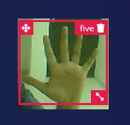
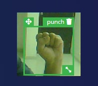
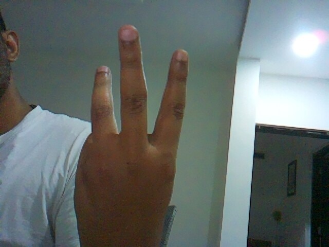
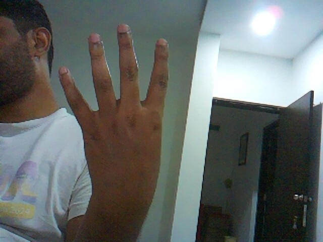
You can see the demo output. There are mainly two objects Punch and Five.
Object: 0	X: 48	Y: 48	Width: 8	Height: 8	Confidence: 87
Five Detected
Sending espnow data
Sent with success

Last Packet Send Status:	Delivery Fail
No objects detected.
No objects detected.
No objects detected.
No objects detected.
No objects detected.
No objects detected.
No objects detected.
No objects detected.
No objects detected.
No objects detected.
No objects detected.
Time consumed: 580
Number of detected objects: 1
Result: Detected
Object: 1	X: 56	Y: 40	Width: 8	Height: 8	Confidence: 61
Punch Detected
Sending espnow data
Sent with success

Last Packet Send Status:	Delivery Fail
No objects detected.
No objects detected.
-
Using Raspberry Pi
I also have trained one more model using Roboflow and Raspberry Pi to control the LEDs using hand gestures. The model can run on Raspberry Pi 4 and final inference results can be sent over socket or other wired/wireless communication protocols. Then the LEDs can be controlled based on Gesture detection
I have collected the images of all five fingers and trained the model based on this dataset.
After training I can run a simple Python code to run and classify image taken in real time using Raspberry Pi camera.
I can then control the LEDs in the similar way I did above.!
Keyword detection models
Keyword detection using Microphone can be one of the applications of ML in smart lighting. Using keywords one can turn on or off the light or change the color of the LED. In my case the Microphones are working as expected. I can collect the sound data and train the ML model just like the one I created above. But for now, I have not yet finished the deployment of this model to the device.
Here is a simple code to collect the data from Microphone using Micropython. The samples that I have collected can be of low volume but it could be processed with Audacity to create proper data for ML training.
from machine import ADC, I2C, Pin, I2S, freq, SPI, SDCard
import time
import os
from time import sleep
import neopixel, machine
import uos

#======= USER CONFIGURATION =======
RECORD_TIME_IN_SECONDS = 30
SAMPLE_RATE_IN_HZ = 22050

#======= USER CONFIGURATION =======
WAV_SAMPLE_SIZE_IN_BITS = 16
WAV_SAMPLE_SIZE_IN_BYTES = WAV_SAMPLE_SIZE_IN_BITS // 8
MIC_SAMPLE_BUFFER_SIZE_IN_BYTES = 4096
SDCARD_SAMPLE_BUFFER_SIZE_IN_BYTES = MIC_SAMPLE_BUFFER_SIZE_IN_BYTES // 2

NUM_SAMPLE_BYTES_TO_WRITE = RECORD_TIME_IN_SECONDS * SAMPLE_RATE_IN_HZ * WAV_SAMPLE_SIZE_IN_BYTES
NUM_SAMPLES_IN_DMA_BUFFER = 256
NUM_CHANNELS = 2


#sd = machine.SDCard(slot=2, cs=machine.Pin(40))

def snip_16_mono(samples_in, samples_out):
    num_samples = len(samples_in) // 4
    for i in range(num_samples):
        samples_out[2*i] = samples_in[4*i + 2]
        samples_out[2*i + 1] = samples_in[4*i + 3]

    return num_samples * 2

def create_wav_header(sampleRate, bitsPerSample, num_channels, num_samples):
    datasize = num_samples * num_channels * bitsPerSample // 8
    o = bytes("RIFF",'ascii')                                                   # (4byte) Marks file as RIFF
    o += (datasize + 36).to_bytes(4,'little')                                   # (4byte) File size in bytes excluding this and RIFF marker
    o += bytes("WAVE",'ascii')                                                  # (4byte) File type
    o += bytes("fmt ",'ascii')                                                  # (4byte) Format Chunk Marker
    o += (16).to_bytes(4,'little')                                              # (4byte) Length of above format data
    o += (1).to_bytes(2,'little')                                               # (2byte) Format type (1 - PCM)
    o += (num_channels).to_bytes(2,'little')                                    # (2byte)
    o += (sampleRate).to_bytes(4,'little')                                      # (4byte)
    o += (sampleRate * num_channels * bitsPerSample // 8).to_bytes(4,'little')  # (4byte)
    o += (num_channels * bitsPerSample // 8).to_bytes(2,'little')               # (2byte)
    o += (bitsPerSample).to_bytes(2,'little')                                   # (2byte)
    o += bytes("data",'ascii')                                                  # (4byte) Data Chunk Marker
    o += (datasize).to_bytes(4,'little')                                        # (4byte) Data size in bytes
    return o

bck_pin = Pin(36)
ws_pin = Pin(37)
sdin_pin = Pin(35)

audio_in = I2S(0,                                 # create I2S peripheral to read audio   # sample data from an INMP441
               mode=I2S.RX, # microphone module
               sck=bck_pin,
               ws=ws_pin, sd=sdin_pin,
               bits=32,
               format=I2S.STEREO,
               rate=22050,
               ibuf=20000
               )

wav = open('sound/green_12.wav','wb')

# create header for WAV file and write to SD card
wav_header = create_wav_header(
    SAMPLE_RATE_IN_HZ,
    WAV_SAMPLE_SIZE_IN_BITS,
    NUM_CHANNELS,
    SAMPLE_RATE_IN_HZ * RECORD_TIME_IN_SECONDS
)
num_bytes_written = wav.write(wav_header)

# allocate sample arrays
#   memoryview used to reduce heap allocation in while loop
mic_samples = bytearray(MIC_SAMPLE_BUFFER_SIZE_IN_BYTES)
mic_samples_mv = memoryview(mic_samples)
wav_samples = bytearray(SDCARD_SAMPLE_BUFFER_SIZE_IN_BYTES)
wav_samples_mv = memoryview(wav_samples)

num_sample_bytes_written_to_wav = 0

print('Starting')

while num_sample_bytes_written_to_wav < NUM_SAMPLE_BYTES_TO_WRITE:
    try:
        # try to read a block of samples from the I2S microphone
        # readinto() method returns 0 if no DMA buffer is full
        num_bytes_read_from_mic = audio_in.readinto(mic_samples_mv)
        if num_bytes_read_from_mic > 0:
            # snip upper 16-bits from each 32-bit microphone sample
            num_bytes_snipped = snip_16_mono(mic_samples_mv[:num_bytes_read_from_mic], wav_samples_mv)
            num_bytes_to_write = min(num_bytes_snipped, NUM_SAMPLE_BYTES_TO_WRITE - num_sample_bytes_written_to_wav)
            # write samples to WAV file
            num_bytes_written = wav.write(wav_samples_mv[:num_bytes_to_write])
            num_sample_bytes_written_to_wav += num_bytes_written
    except (KeyboardInterrupt, Exception) as e:
        print('caught exception {} {}'.format(type(e).__name__, e))
        break
IMU based gesture detection
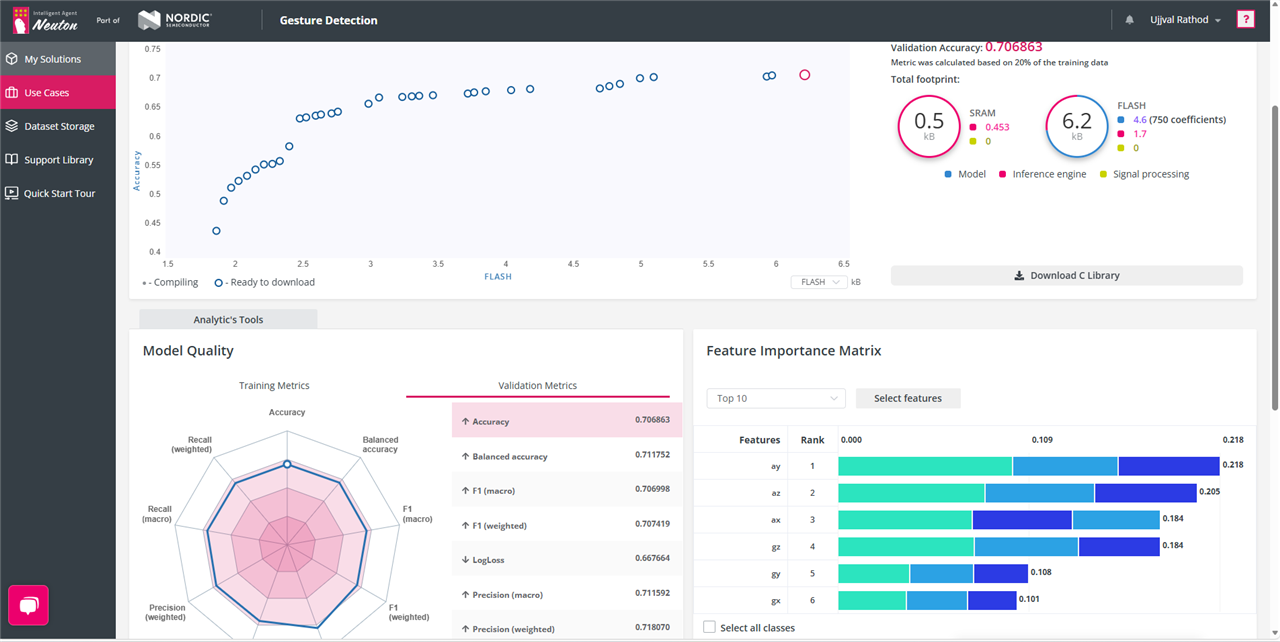
Data from IMU sensors such as Accelerometer and Gyroscope could be used to train the ML model. For this I thought of trying something different. I decide to train a model using neuton.ai platform to create a lightweight model that can be easily integrated into ESP32s3 device. This model can detect various hand movements and control the LED lights.
For collecting the data in .csv (suggested by the neuton.ai docs) format I am using the following Micropython code. The data collected then can be used to train the model on neuton.ai platform. I have collecting approx 10 samples for each movement. Each movement is one and half seconds long.
Here are the movement types that I am collecting the data for.
- Round circle
- up-down movement
- Wave movement
from machine import Pin, I2C, ADC
import time
import machine
import struct
import neopixel

data = struct.pack('hhl', 1, 3)
print(data)

_ICM2670P_ADDRESS = 0x68

_TEMP_HIGH = 0x09
_TEMP_LOW = 0x0A
_PWR_MGMT0 = 0x1F

_GYRO_CONFIG0 = 0x20
_ACCEL_CONFIG0 = 0x21
_GYRO_CONFIG1 = 0x23
_ACCEL_CONFIG1 = 0x24
_APEX_CONFIG1 = 0x26
_APEX_CONFIG12 = 0x67
_ACCEL_DATA_X1H = 0x0B
_ACCEL_DATA_X1L = 0x0C

_ACCEL_DATA_Y1H = 0x0D
_ACCEL_DATA_Y1L = 0x0E

_ACCEL_DATA_Z1H = 0x0F
_ACCEL_DATA_Z1L = 0x10

_GYRO_DATA_X1H = 0x11

_INT_CONFIG = 0x06
_INT_CONFIG0_M1 = 0x04
_INT_CONFIG1_M1 = 0x05
_SENSOR_CONFIG3_M1 = 0x06
_ST_CONFIG = 0x13
_INT_SOURCE0 = 0x2B
_INT_SOURCE1 = 0x2C

_INT_SOURCE3 = 0x2D
_INT_SOURCE4 = 0x2E

_INT_SOURCE6_M1 = 0x2F
_INT_SOURCE7_M1 = 0x30
_INT_SOURCE8_M1 = 0x31
_INT_SOURCE9_M1 = 0x32
_INT_SOURCE10_M1 = 0x33

_INTF_CONFIG0 = 0x35
_INTF_CONFIG1 = 0x36
_INT_STATUS_DRDY = 0x39
_INT_STATUS = 0x3A
_INT_STATUS2 = 0x3B
_INT_STATUS3= 0x3C

_APEX_CONFIG0 = 0x25
_APEX_CONFIG1 = 0x26
_APEX_CONFIG2_M1 = 0x44
_APEX_CONFIG3_M1 = 0x45
_APEX_CONFIG4_M1 = 0x46
_APEX_CONFIG5_M1 = 0x47
_APEX_CONFIG9_M1 = 0x48
_APEX_CONFIG10_M1 = 0x49
_APEX_CONFIG11_M1 = 0x4A
_APEX_CONFIG12_M1 = 0x67

_APEX_DATA0 = 0x31
_APEX_DATA1 = 0x32
_APEX_DATA2 = 0x33
_APEX_DATA3 = 0x34
_APEX_DATA4 = 0x1D
_APEX_DATA5 = 0x1E

_WOM_CONFIG = 0x27
_ACCEL_WOM_X_THR = 0x4B
_ACCEL_WOM_Y_THR = 0x4C
_ACCEL_WOM_Z_THR = 0x4D

_BLK_SEL_W = 0x79
_MADDR_W = 0x7A
_M_W = 0x7B
_BLK_SEL_R = 0x7C
_MADDR_R = 0x7D
_M_R = 0x7E

_PADOMETER_LOW = 0x31
_PADOMETER_HIGH = 0x32

class ICM42670P(object):
    def __init__(self, interface = 1, sda_pin=39, scl_pin=40, cs=3, addr_sel=38, _address=_ICM2670P_ADDRESS, freq=400000):

        csp = Pin(cs, Pin.OUT)
        addr_selp = Pin(addr_sel, Pin.OUT)

        csp.value(1)
        addr_selp.value(0)

        sda_p = Pin(sda_pin)
        scl_p = Pin(scl_pin)

        self.i2c = I2C(1, sda = sda_p, scl = scl_p, freq=freq)

        self.int1 = Pin(1, Pin.IN)
        self.int2 = Pin(2, Pin.IN)

        print(self.i2c.scan())
        who_am_i = 0
        buf = bytes(b'\x75')
        self.i2c.writeto(_ICM2670P_ADDRESS, buf, True)
        who_am_i = self.i2c.readfrom(_ICM2670P_ADDRESS, 1, True)
        data = int.from_bytes(who_am_i)
        print(hex(data))

    def get_temprature(self):

        self.i2c.writeto_mem(_ICM2670P_ADDRESS, _PWR_MGMT0, b'\x0F')
        time.sleep(0.05)
        temp0 = (self.i2c.readfrom_mem(_ICM2670P_ADDRESS, _TEMP_HIGH, 1))
        temp1 = (self.i2c.readfrom_mem(_ICM2670P_ADDRESS, _TEMP_LOW, 1))

        temprature = (int.from_bytes(temp0) << 8) | int.from_bytes(temp1)
        t = (temprature / 128) + 25
        data = t
        print('Temprature ', t, '*C')
        return t

    def enable_imu(self):
        # we want to put both accelerometer and gyroscope to LN mode
        # if you want to put to LP mode write 0x0A
        self.i2c.writeto_mem(_ICM2670P_ADDRESS, _PWR_MGMT0, b'\x1F')
        #self.i2c.stop()
        time.sleep(0.05)
        return 0

    def set_accel_rate(self):
        self.i2c.writeto_mem(_ICM2670P_ADDRESS, _ACCEL_CONFIG0, b'\x08')
        time.sleep(0.05)
        self.i2c.writeto_mem(_ICM2670P_ADDRESS, _ACCEL_CONFIG1, b'\x07')
        time.sleep(0.05)
        return 0

    def enable_APEX(self):
        self.i2c.writeto_mem(_ICM2670P_ADDRESS, _INT_CONFIG, b'\x3F')
        time.sleep(0.05)
        self.i2c.writeto_mem(_ICM2670P_ADDRESS, _INT_SOURCE0, b'\x00')
        time.sleep(0.05)
        self.i2c.writeto_mem(_ICM2670P_ADDRESS, _INT_SOURCE1, b'\x00')
        time.sleep(0.05)
        self.i2c.writeto_mem(_ICM2670P_ADDRESS, _INT_SOURCE3, b'\x00')
        time.sleep(0.05)
        self.i2c.writeto_mem(_ICM2670P_ADDRESS, _INT_SOURCE4, b'\x00')
        time.sleep(0.05)
        self.i2c.writeto_mem(_ICM2670P_ADDRESS, _APEX_CONFIG0, b'\x01')
        time.sleep(0.05)
        self.i2c.writeto_mem(_ICM2670P_ADDRESS, _APEX_CONFIG1, b'\x22')
        time.sleep(0.05)
        self.i2c.writeto_mem(_ICM2670P_ADDRESS, _APEX_CONFIG12, b'\x00')
        time.sleep(0.05)
        self.i2c.writeto_mem(_ICM2670P_ADDRESS, _APEX_DATA4, b'\x03')
        time.sleep(0.05)
        self.i2c.writeto_mem(_ICM2670P_ADDRESS, _APEX_DATA5, b'\x00')
        time.sleep(0.05)


    def write_mag_register(self, banknum, registeraddr, value):
        self.i2c.writeto_mem(_ICM2670P_ADDRESS, _BLK_SEL_W, b'\x00')
        time.sleep(0.05)
        self.i2c.writeto_mem(_ICM2670P_ADDRESS, _MADDR_W, registeraddr.to_bytes(1))
        time.sleep(0.05)
        self.i2c.writeto_mem(_ICM2670P_ADDRESS, _M_W, value.to_bytes(1))
        time.sleep(0.05)

    def clear_int(self):
        print()
        self.i2c.readfrom_mem(_ICM2670P_ADDRESS, _INT_STATUS3, 1)

    def set_gyro_rate(self):
        self.i2c.writeto_mem(_ICM2670P_ADDRESS, _GYRO_CONFIG0, b'\x08')
        time.sleep(0.05)
        self.i2c.writeto_mem(_ICM2670P_ADDRESS, _GYRO_CONFIG1, b'\x01')
        time.sleep(0.05)
        return 0

    def read_raw_accelerometer(self):
        # Assume _ACCEL_DATA_X1H is the base address for X axis high byte
        data = self.i2c.readfrom_mem(_ICM2670P_ADDRESS, _ACCEL_DATA_X1H, 6)
        ax = int.from_bytes(data[0:2], "big")
        ay = int.from_bytes(data[2:4], "big")
        az = int.from_bytes(data[4:6], "big")
        #print(ax/2048, ay/2048, az/2048)
        return (ax, ay, az)

    def read_raw_gyroscope(self):
        data = self.i2c.readfrom_mem(_ICM2670P_ADDRESS, _GYRO_DATA_X1H, 6)
        gx = int.from_bytes(data[0:2], "big")
        gy = int.from_bytes(data[2:4], "big")
        gz = int.from_bytes(data[4:6], "big")
        return (gx, gy, gz)

    def get_accerometer(self):
        ax, ay, az = self.read_raw_accelerometer()

        accx = self.get_twos_complement(ax)
        accy = self.get_twos_complement(ay)
        accz = self.get_twos_complement(az)

        gx, gy, gz = self.read_raw_gyroscope()

        gyrx = self.get_twos_complement(gx)
        gyry = self.get_twos_complement(gy)
        gyrz = self.get_twos_complement(gz)

        print(accx/2048, "       \t   ", accy/2048, "       \t   ", accz/2048, "    \t", gyrx, "\t", gyry, "\t", gyrz, "\t", 0)

    def get_twos_complement(self, value):
        if(value & 0x8000):
            data = value - 0x10000
        else:
            data = value
        return data

    def read_padometer(self):
        data = self.i2c.readfrom_mem(_ICM2670P_ADDRESS, _PADOMETER_LOW, 2)
        steps = int.from_bytes(data[0:2], "big")
        print(self.get_twos_complement(steps))
        print('detected activity')
        act = self.i2c.readfrom_mem(_ICM2670P_ADDRESS, _APEX_DATA3, 1)
        print(act)

IMU = ICM42670P()
IMU.enable_imu()
IMU.set_accel_rate()
IMU.enable_APEX()
IMU.write_mag_register(0, _INT_SOURCE6_M1, 0x80)
IMU.write_mag_register(0, _INT_CONFIG0_M1, 0x00)
IMU.write_mag_register(0, _INT_CONFIG1_M1, 0x10)

print('Start')

x=0
time.sleep(0.2)
status = ADC(IMU.int1)

while(True):
    #IMU.get_accerometer()
    IMU.get_temprature()
    #IMU.read_raw_accelerometer()
    time.sleep(0.05)
    x += 1
    if(x == 150):
        break
    #IMU.get_temprature()
I have already trained the model successfully and got approx. 70% accuracy. After training is completed, I got a file containing the trained model for deployment to the device. I can use this model to integrate into my code and control the LEDs based on that
(At the moment I am still working on this)
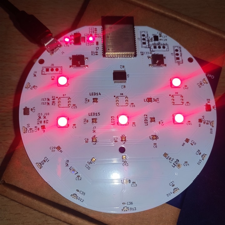
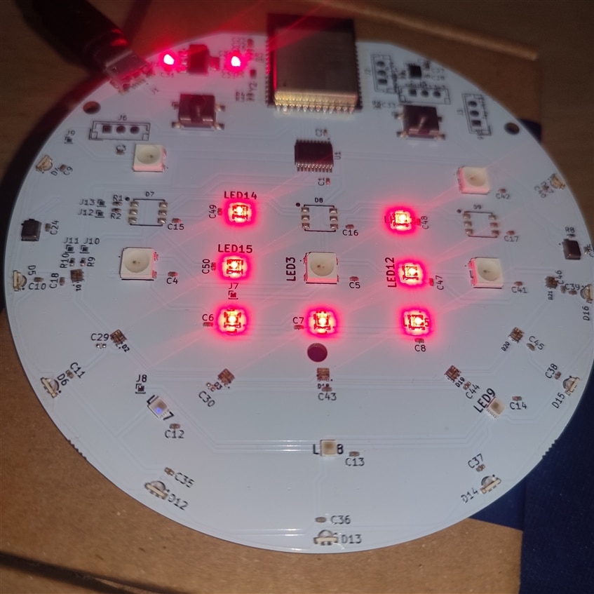
Adding effects
Effects are ways to make LEDs look more interactive and decorative. There are different effects that are possible with colorful LEDs. I have tried to create some.
- Rainbow Effect
Rainbow effect is one of the very basic LED effects. This effect generates color similar to a Rainbow and changes this color between number of LEDs in the strip.
- Fading Effect
Fading effect is like making a strip to full brightness and then again making brightness to zero. This effect looks catchy in some decorative light's scenarios.
- Cycling Effect
Cycling is way to cycle through the strip and make each LED brighter than the others one by one in a sequence.
The following is video illustration of Effects using LEDs and Micropython code.
import neopixel
import machine
import time
import esp32
from machine import PWM, Pin

class LIGHT_EFFECTS(object):

    def __init__(self, interface = 2, miso = 38, mosi = 14, sck=10, num_led = 7, firstbit=0):

        self.spi_num = interface
        self.sck_pin = Pin(sck)
        self.miso_pin = Pin(miso)
        self.mosi_pin = Pin(mosi)
        self.first_bit = firstbit
        self.leds = num_led
        self.spi = machine.SPI(self.spi_num, baudrate=8000000, polarity = 0, phase = 0, sck = self.sck_pin, mosi = self.mosi_pin, miso = self.miso_pin, firstbit=self.first_bit)
        self.start_frame = bytes([0x00, 0x00, 0x00, 0x00])

    def send_start(self):
        self.spi.write(self.start_frame)

    def get_pixel(self, b, g, r):
        return b, g, r

    def prepare_frame(self, leds, r, g, b):
        frame = []
        b, g, r = self.get_pixel(r, g, b)

        for i in range(self.leds):
            frame.append(0xFC)
            frame.append(b)
            frame.append(g)
            frame.append(r)
        self.send_start()
        self.spi.write(bytearray(frame))
        self.spi.write('b\x07')
        time.sleep_us(50)

    def wheel(self, pos):
        if(pos) < 85:
            return (pos * 3, 255 - pos * 3, 0)
        elif pos < 170:
            pos -= 85
            return (255 - pos * 3, 0, pos * 3)
        else:
            pos -= 170
            return (0, pos * 3, 255 - pos * 3)

    def rainbow_cycle(self, wait, numled, pin_num):
        neopixel_id = neopixel.NeoPixel(machine.Pin(pin_num), numled)
        for j in range(255):
            for i in range(numled):
                pixel_index = (i * 256 // numled) + j
                neopixel_id[i] = self.wheel(pixel_index & 255)
                neopixel_id.write()
                time.sleep(wait)

    def rainbow_cycle_spi(self, wait, numled, pin_num):
        frame = []
        self.spi = machine.SPI(self.spi_num, baudrate=8000000, polarity = 0, phase = 0, sck = self.sck_pin, mosi = self.mosi_pin, miso = self.miso_pin, firstbit=self.first_bit)

        for j in range(255):
            for i in range(self.leds):
                pixel_index = (i * 256 // numled) + j
                r, g, b = self.wheel(pixel_index & 255)
                frame.append(0xFC)
                frame.append(b)
                frame.append(g)
                frame.append(r)
            self.spi.write(self.start_frame)
            self.spi.write(bytearray(frame))
            self.spi.write('b\x07')
            time.sleep(wait)
            frame = []

    def wheel2(self, pos):
        if(pos) < 1365:
            return (pos * 3, 4096 - pos * 3 , 0)
        elif pos < 2730:
            pos -= 85
            return (4096 - pos * 3 , 0, pos * 3)
        else:
            pos -= 2730
            return (0, pos * 3, 4096 - pos * 3 )

    def rainbow_cycle_spi2(self, wait, numled):
        frame = []
        self.spi = machine.SPI(self.spi_num, baudrate=8000000, polarity = 0, phase = 0, sck = 40, mosi = 13, miso = 38, firstbit=0)

        for i in range(numled):
            for k in range(48):
                if((color >> i) & 0x1):
                    frame.append(0xFC)
                else:
                    frame.append(0xC0)

            send = bytearray(frame)
            self.spi.write(send)
            time.sleep(wait)
            frame = []

    def fadding(self, r, g, b):
        neo1 = neopixel.NeoPixel(machine.Pin(12), 9)
        neo2 = neopixel.NeoPixel(machine.Pin(47), 7)
        neo3 = neopixel.NeoPixel(machine.Pin(45), 5)

        for i in range(0 , 256 , 5):
            for j in range(9):
                neo1[j] = (i, 0, i)
            for j in range(7):
                neo2[j] = (i, 0, i)
            for j in range(5):
                neo3[j] = (i, 0, i)

            neo1.write()
            neo2.write()
            neo3.write()
            self.prepare_frame(7, 0, i, 0)
            time.sleep(0.01)

        for i in range(255 , -1 , -5):
            for j in range(9):
                neo1[j] = (i, 0, i)
            for j in range(7):
                neo2[j] = (i, 0, i)
            for j in range(5):
                neo3[j] = (i, 0, i)

            neo1.write()
            neo2.write()
            neo3.write()
            self.prepare_frame(7, i, 0, i)
            time.sleep(0.01)

    def chassing(self):
        neo1 = neopixel.NeoPixel(machine.Pin(12), 9)
        neo2 = neopixel.NeoPixel(machine.Pin(47), 7)
        neo3 = neopixel.NeoPixel(machine.Pin(45), 5)

        for i in range(9):
            for j in range(9):
                if i == j:
                    neo1[j] = (255, 0, 0)
                else:
                    neo1[j] = (5, 0, 0)
                neo1.write()
                time.sleep(0.01)

        for i in range(7):
            for j in range(7):
                if i == j:
                    neo2[j] = (255, 0, 0)
                else:
                    neo2[j] = (5, 0, 0)
                neo2.write()
                time.sleep(0.01)

        for i in range(5):
            for j in range(5):
                if i == j:
                    neo3[j] = (255, 0, 0)
                else:
                    neo3[j] = (5, 0, 0)
                neo3.write()
                time.sleep(0.01)


eff  = LIGHT_EFFECTS()

while True:
#     eff.chassing()
     eff.fadding(20,20,20)
#     eff.rainbow_cycle(0.0000001, 9, 12)
#     eff.rainbow_cycle(0.00001, 7, 47)
#     eff.rainbow_cycle(0.000001, 5, 45)
#     eff.rainbow_cycle_spi(0.01, 5, 45)
    #eff.rainbow_cycle_spi2(0.001, 3)
Conclusion and the Future work
Overall, it was my pleasure to take part in this challenge. I would like to thank Element14 community for giving me this opportunity to be part of this challenge. Then I would like to give special thanks to NextPCB for their outstanding support in creating this PCB and making the dream that I had into a working prototype. I would also like to thank Würth Elektronik for the kind of LED products that they have. Before this challenge, I had no idea that there are so many different kinds of programmable LEDs that one can use into their products. I would also thank to Edge Impulse for their support for documentation and the firmware.
In the software part, I liked to use Micropython for this device. It made my tasks simple and efficient and saved lots of hours of compiling and running code. Overall, I enjoyed it.
The device that I created for this challenge has so many possibilities be it for learning platform or a working product. I wanted to explore more of its capabilities running ML models. This way we can create a smart light that has interesting features. It also motivates us about the future of AI and its applications.
Lastly, there are some improvements that are possible with this device. I hope that in the next iterations I can work on those improvements. First thing is that I can use USB-C type connection to improve power delivery to the LEDs as it can draw more current than micro usb. Then I can add some power jack to be able to use this as product/smart light in real field. I can also add camera or gesture sensor to this device to have more features and ways to control the LEDs.