


In my last posting, I looked at the Light Up Your Life Design Challenge kit and all that was included. In this posting, I’ll be covering the topic of soldering SMD LEDs at home – perhaps one of the key aspects of this design challenge which may have caused some applicants to turn away.
SMD LEDs can be tricky!
Through-hole components were my introduction to electronics, being easy to handle by hand. The use of SMD components are now ubiquitous and they are designed for automated assembly. Assembling SMD components by hand takes new techniques and tools, but is also often fiddly due to the smaller component sizes.
In commercial automated manufacturing, components are handled on tape and reels with pick and place machines taking components from the tape and placing them onto PCBs. The reels are stored in temperature and humidity-controlled conditions, or are refreshed before use through a baking process. The PCBs have a coating of solder paste which has been dispensed through a stencil containing apertures corresponding to the pads – the paste serves to temporarily keep the component in place but also contains both the flux and solder to join the component onto the board. The boards are then conveyer belted through a reflow oven which has multiple zones – heating up to very specific temperatures at particular rates, holding for a very specific amount of time, before letting the boards cool down. In one fell swoop, all the soldering is done in the space of around 10 seconds around the peak temperature (245-260 degrees Celsius) – with the remaining being pre-heating and cooling to avoid thermal shocks.
Of course, at home, most of us don’t have such luxuries. For one, I don’t have solder paste simply because it’s a perishable consumable – it very often goes bad before I have a chance to use it up. The next is that the Adafruit breakouts we are given are nice, but we don’t have a stencil, so even if we had solder paste, it would be a bit tricky to use it effectively. I don’t have a reflow oven (and I don’t advise using cooking ovens both for food safety and due to the lack of consistent heating or accurate thermostats), nor do I have a hot-plate for soldering either.
But things get worse than that – LED packages are unlike the hardy ceramic packages you find for capacitors and resistors. They have plastic bodies and often epoxy lenses – these are very temperature sensitive and don’t like being blasted with heat.
So, it’s not surprising that the requirement for soldering SMD LEDs may have put some design challenge applicants off from applying for this one.
A Leisurely Video of SMD Soldering
As part of this particular post, I thought I’d take a slightly different approach and film a video of me attempting to do SMD soldering of the WL-ICLEDs myself. Please excuse my voice, as it was filmed as I was still recovering from the flu (editing out the coughs was tough), but also, at a time when I have partially lost vision in my left eye, causing some difficulties with depth perception. On the upside, this upload is in 4K resolution for those who might want a clearer view and I broke out the macro lens as well.
Let me know what you think …
Techniques and Lessons
For those who don’t have time to devote to the video, here’s a summary of sorts. For those without a reflow oven or a hot-plate, I’d recommend either using the soldering iron and tweezer method, or the hot-air-gun method (with soldering iron and tweezers, naturally).
Soldering Iron Method
- Pre-tin just one corner pad with sufficient solder to make a joint.
- Holding the package with tweezers in the other hand, position it precisely as possible. Heat up the tinned pad to form the first joint. Keep the iron at a moderate temperature to avoid trauma to the package – I often use about 315 degrees Celsius, but depending on the solder, you could go lower.
- If the alignment is correct, proceed to solder the other pins down, starting with the opposite side (ideally). If not, re-heat the joint and nudge carefully with the tweezers.
- It’s unlikely you will get perfect alignment, but a serviceable result for prototype purposes should still be possible.
Hot Air Gun Method
- Pre-tin the pads with sufficient solder to make the joints, ideally a wire containing water-based flux for easy cleaning and no residue. Lower temperature solders usually help, so I often use leaded solder for this.
- Brush the pads with flux – I use a water-based flux pen which is compatible with the solder flux (in case any remains).
- Position the SMD LEDs close to their final alignment.
- Heat the board from underneath – I usually have a moderate flow and temperature set to about 315 degrees Celsius. As the board “shields” the plastics of the LED package and lens from direct airflow, it should protect the LED from charring, but not if the air is coming in at an angle.
- When the SMD package “jiggles” into position, keep the heat on for a couple of seconds longer to ensure heat flows evenly through the joint then remove the heat gun and let the board cool before handling.
- If the package doesn’t settle nicely into place, you can nudge it with a tweezer once the solder is all liquid to get it to “snap”.
- Wash the board to clean the flux – important if you are using a flux that requires cleaning. No clean flux may remain on the board, but may show discolouration.
Of course, these aren’t the intended way these components are to be used, but with sufficient care, it should be possible to build working prototypes even with such crude techniques.
A Closer Look at the Results
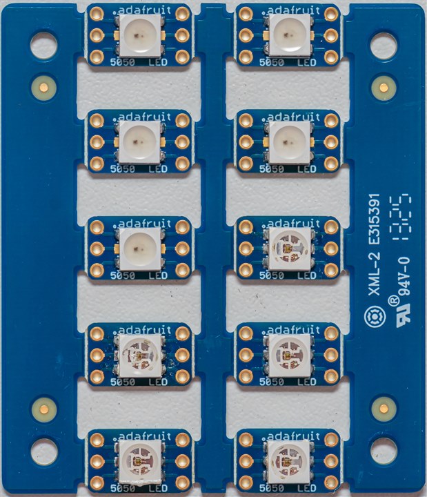
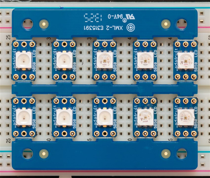
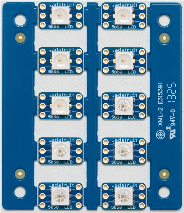
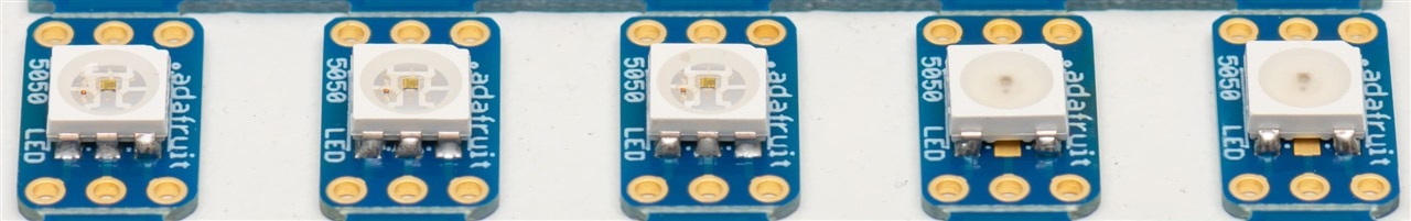
After washing, the toll became clear. If we number the LEDs going across from left to right (1,2) then down by rows (3,4) until we get to the bottom (9,10), we can identify a few issues.
The four-pad LEDs [1,5] are all done using leaded solder and hot-air gun method. They’re actually all looking very good – except for some non-planarity because of too much solder on some pads causing them to angle very slightly, they’re about as good as I’d expect.
The LED [6] is the one hand-done with SN100C lead-free and it’s showing some signs of heat stress. It’s very subtle though – looking at the angled “cup”, we can see three spots where the lens seems to have bubbled away from the plastic base corresponding to three of the leads. That’s a clear case of heat damage, but not likely to be a major consequence.
On the other hand, LED [7] was soldered with SAC305 lead-free and that was very challenging. Not only did I cook the legs causing the plastic base to mushroom, post-wash, it’s clear that the optical resin used to pot the LED has become damaged too. Perhaps this LED might take a life-expectancy-hit and a bit of a modified optical performance, but it should still work. It’s not a good result. There's also what seems to be no-clean flux residue as well.
The hot-air-gun LED [8] is doing just fine … while LED [9] has the charred bottom lip and a slight bubbling on that area too. Finally LED [10] also shows bubbling around the three left leads, but not all that significant. I’d say this is strongly in favour of the hot-air-gun method but perhaps I need to turn down my soldering iron tip temperature too …
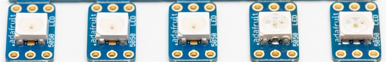
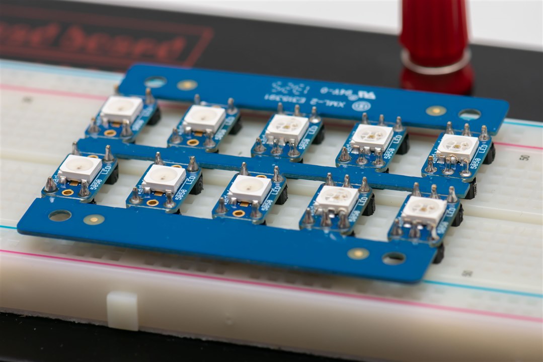
From the edge, we can see the various levels of “toastiness” that the leads got to, thanks to my soldering iron technique.
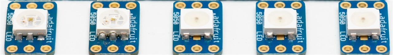
I will say that the Adafruit break-out is genius though. It’s designed such that the holes line-up perfectly on a 2.54mm grid, so that you can easily use a breadboard to help you get the header pins lined up. Unfortunately, I realised I was running low on header pins (something you never really expect to run out of) so I had to ration just four pins for those LEDs with four connections.
Since heat is much less of a danger here, I went with the SN100C lead-free (my favourite lead-free alloy at this point) so as to break my habit of just using leaded solder.
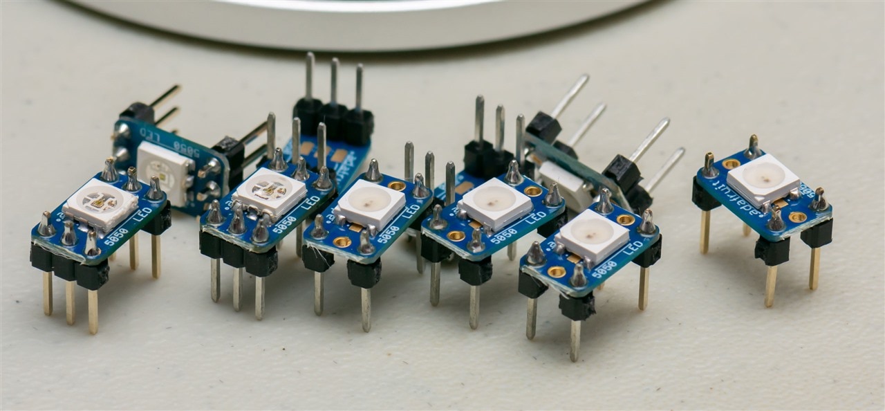
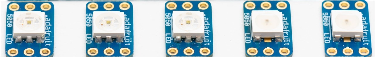
Then, carefully, the board can be snapped apart along the V-scores to produce individual plug-in units. Very nice!
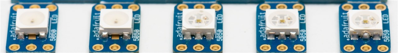
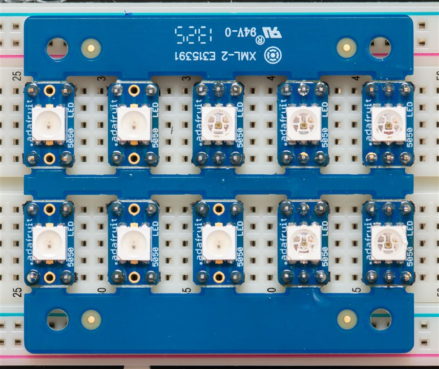
Five of each was nice, but I decided that ten would be better. It’s hard to demonstrate anything particularly handy with just five, so this time, I went hot air gun on all of them. I saw two minor bubbles in the clear epoxy on LED [6] but that was no drama. I’m wondering if this is also because these LEDs were not properly packaged in terms of moisture control and I certainly didn’t pre-bake them prior to use.
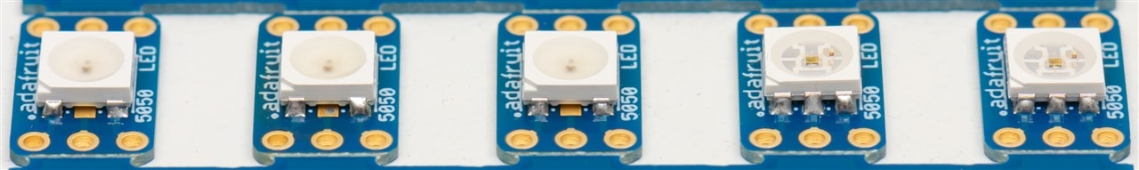
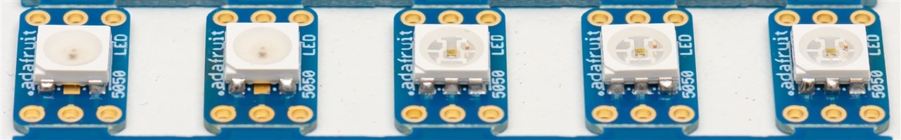
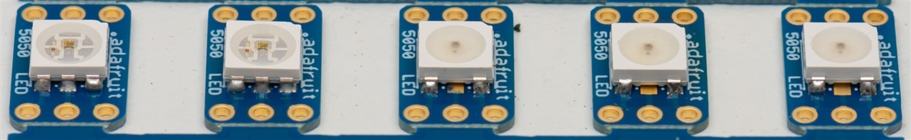
Much nicer looking from the edges this time, but not all joints are quite as nice looking as they could be, in part due to slightly excessive solder.
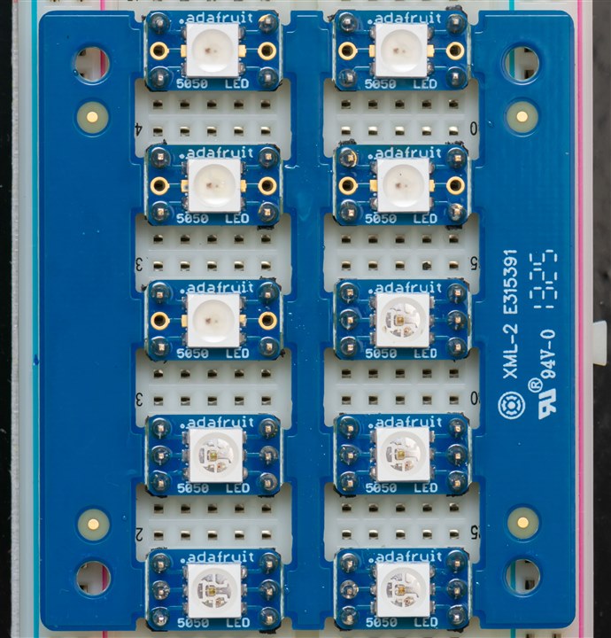
Header pins go in – this time, I had to break open some unused break-outs just to steal their included header pins. I’m facing a header-pin crisis here! Thankfully, I do have a batch of ~20,000 header pins on their way … it will just take some time.
With that, I should have enough to get started breadboarding up the WL-ICLEDs for testing to see if they will work as intended.
Conclusion
The soldering of SMD LEDs is a bit trickier than any ordinary SMD resistor or capacitor which is extremely heat tolerant. The LED packages use plastics and resins that are often very temperature sensitive and hot-air-gun from the top side often results in cooking the LEDs to a crisp, especially with units that have poor temperature consistency. When using pre-prepared break-out boards, there is no stencil and few people have solder paste or hotplates at their disposal – so a humble soldering iron and possibly a hot air gun is all that might be available.
But as I’ve experimented over time and “calibrated” my hands, I’ve discovered it is possible to solder such components even with such limitations, albeit, with the chance of overstressing the component and causing failure. The hot air gun method is much quicker and much more reliable (in my experience) with less trauma, while the soldering iron method requires very steady hands, good luck and a fine soldering tip. It rarely results in nicely aligned results, but it will still work.
Perhaps in the end, building your own reflow oven might be a worthwhile task – but for now, I guess I can still proceed to test some of the WL-ICLEDs using the Adafruit breakouts alone. That will give me the confidence to progress to a PCB design, which, when it arrives, I will have to assemble.


