


In the previous two instalments, I covered the contents of the kit including close-up images of the LEDs themselves and the potentially daunting task of soldering the 5050-size WL-ICLEDs to the breakouts. Now, it’s time to put them to good use.
Installing the Arduino Zero
The first step for lighting up the LEDs is to get the Arduino Zero operational. As I already have an installation of Arduino IDE with the Arduino SAMD Boards package installed from my previous run-ins with the MKR-series, it was an almost plug-and-play process.


The top port is what you would want to use if loading with the IDE, as the bottom port appears to be for the onboard debugger. The associated PIDs and VIDs are shown in the screenshots above.
But I had an interesting issue. The board comes pre-loaded with the blink sketch, so the LED marked “L” cycles on and off repeatedly. To load a new sketch, I selected the board in question and the COM port, but trying to load a program did not work. Instead, it would perform the 1200bps reset procedure … then sit “waiting” for the zero to come back in bootloader mode to actually flash the program, eventually timing out.
As I had some experience with MKR boards, I knew of the double-click-the-reset-button-to-enter-bootloader trick. So I hit load again, but when it says “waiting”, a quick double-click and the Zero was recognised on a new COM port, the sketch loaded with a flurry of debug messages and we’re off to the races!

Choosing FastLED
The next thing is to drive the LEDs. While Würth Elektronik do have their own SDK, looking at the datasheets, it seemed that the LEDs are basically compatible with existing types of integrated-controller type RGB LEDs. As a result, it was easier to choose the widely-supported and well-understood FastLED library to handle this, rather than set-up PlatformIO. This is especially true as I would eventually choose to migrate away from the SAMD platform entirely, but also because FastLED seems to be actively developed with a clear focus on speed.
But one thing to note – FastLED supports a lot of different types of LED, so it’s important to choose the correct type to ensure proper operation. The naming of the types of LED are often by “popular” product names (WSxxxx, APAxxx, NSxxx, SKxxxx, TMxxx, UCSxxxx). The actual manufacturer of the silicon is not necessarily who the specific driver is named after and some LED manufacturers have taken great pains to try and differentiate their products from others even though they may be using the same protocol or even the same silicon. That is because an LED is more than just the protocol and controlling silicon – it’s also the quality of the LED dies, the consistency of the LED dies in terms of wavelength and output power, the quality of the package materials and construction in terms of alignment and more.
So please keep in mind, while I may say that it “works” with a particular setting, I am not implying that the LEDs themselves are equivalent to other LEDs on the market which use the same designation even if they may share the control protocol and timings. One good reason for choosing Würth is simply that they have a good reputation for quality products, backed by good data and a strong supply chain. It also makes me wish there was a simple way to authenticate such parts as being authentic - you might specify one part number but your contract manufacturer could be quietly substituting another "compatible" part and it could be very difficult to know!
But that being said, upon examination of the data, it would seem that the 6-pin 5050-size LEDs (1315050930246) use a control protocol compatible with APA102 with pixel order BGR, while the 4-pin 5050-size LEDs (1515050930002) use a control protocol most compatible with WS2812B (800kHz), but seemed to operate just fine with WS2811 selected (unsure if FastLED uses a 400kHz timing for that or not as there’s been many changes there). The pixel order is GRB.
Achieving First Light
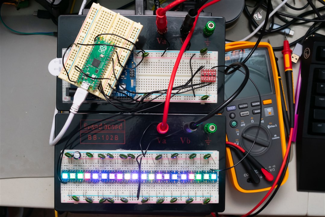
To achieve first light, I first had to spend an hour or two breadboarding up my 20 LEDs for power and daisy chaining data and/or clock connections. This was a therapeutic exercise, although one I decided to do with “bare” tinned copper (i.e. stripped solid core wire) as I felt that might look a bit better. I don’t usually stock much colour variety when it comes to wire – so if it wasn’t bare, all my wires would be black.
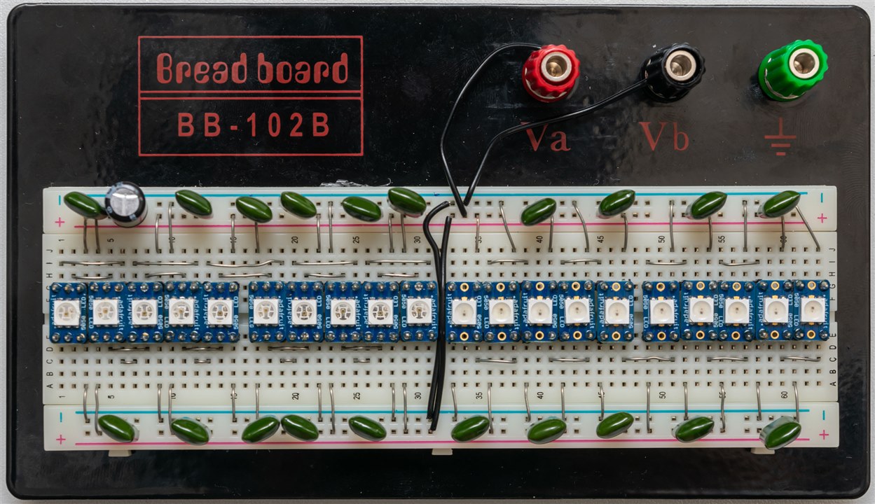
Persistence pays off, but also being conscientious. I didn’t want any accidents.
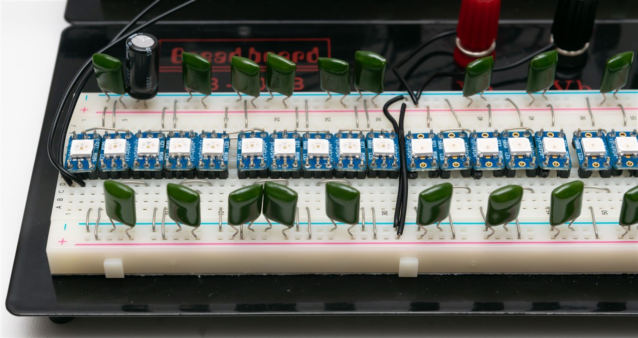
I’ve sprinkled a lot of 100nF greencap capacitors (as I had them lying around) onto the power distribution rails, since the PWM of the LEDs can modulate the supply and create quite a bit of noise. As the LEDs themselves contain an IC, ensuring somewhat stable power is important to avoid malfunctions. I’ve also added a bigger electrolytic to the board since it’s going to be getting power from somewhere else … along some unavoidable length of wire.
But as you would have noticed, there’s now no space for anything else, so thanks to element14 for having the foresight to supply a second breadboard.
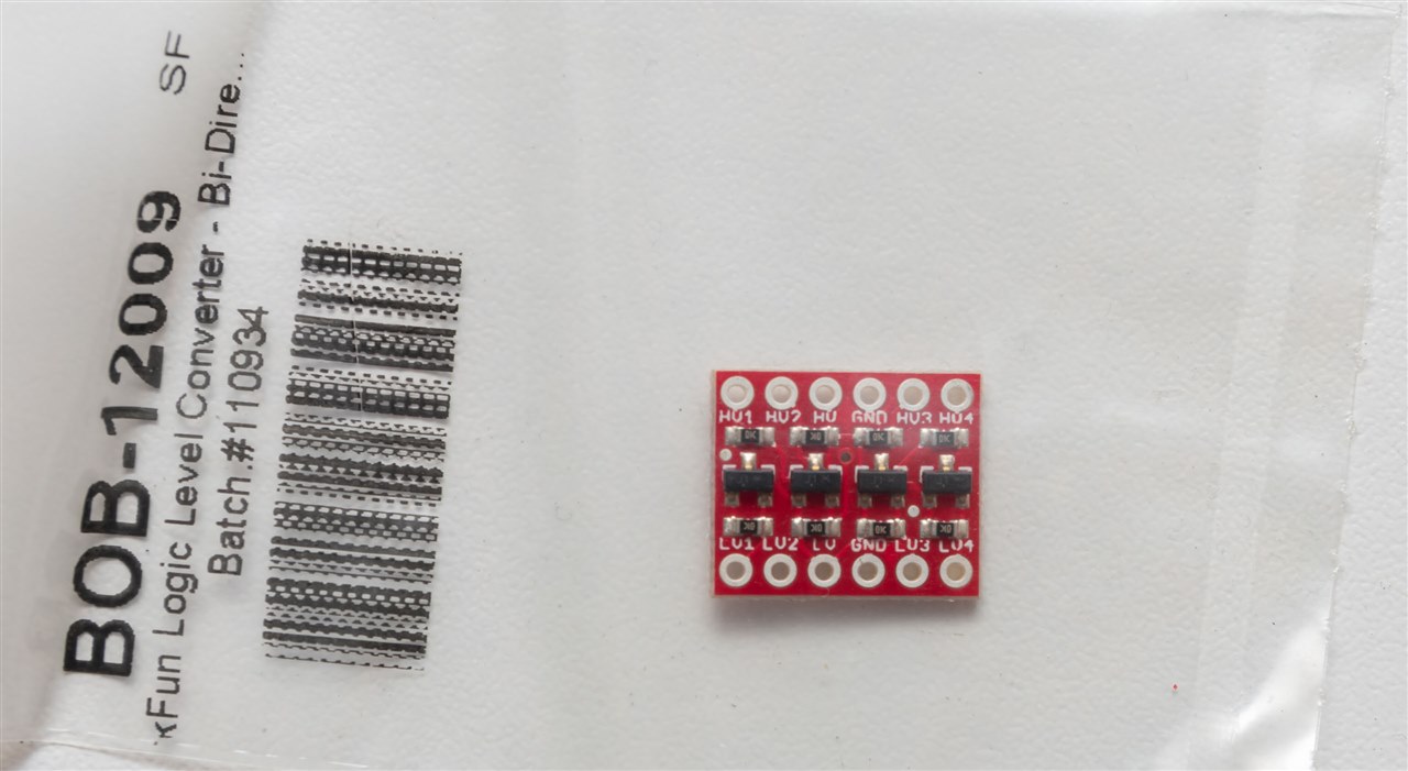
The next issue was the level shifter. The supplied IC had no breakout, which meant I couldn’t use it directly on the breadboard. After digging through my bin of unused bits, I managed to find a Sparkfun BOB-12009, a level shifter based on BSS138 MOSFETs and pull-up resistances – it’s crude but it certainly works at I2C rates. Perhaps clocking down a little on the synchronous-bus type would help ensure it works.
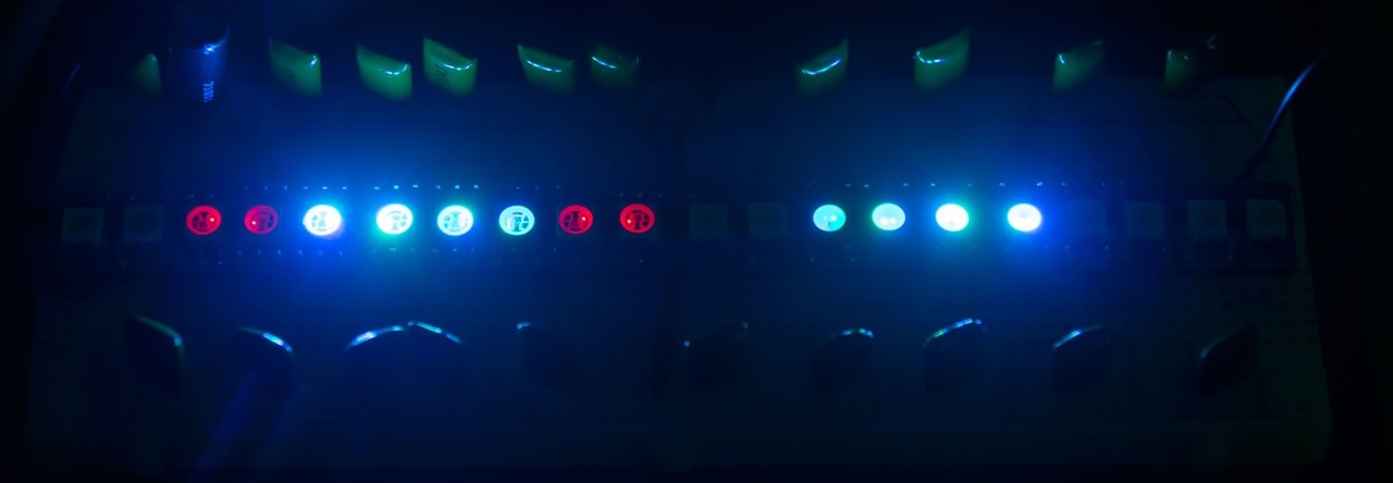
To test the LEDs, there will need to be a demonstration of sorts, so I opted to run the most traditional FastLED demonstration of all – one called demoreel100.ino. To make this work, I modified it to define two different LED strips with the controller parameters I’ve mentioned earlier, and duplicated each led array modification call with another one for the second LED array (led2). It’s not pretty, but it should work.
// element14 Light-Up-Your-Life Design Challenge
// by Gough Lui - October 2025
// Modified to support two strings of Wurth-Elektronik LEDs
// String 1 = 10 x 1515050930002
// String 2 = 10 x 1315050930246
// on an Arduino Zero with a BSS138-based Level Shifter.

/// @file    DemoReel100.ino
/// @brief   FastLED "100 lines of code" demo reel, showing off some effects
/// @example DemoReel100.ino

#include <FastLED.h>

// FastLED "100-lines-of-code" demo reel, showing just a few
// of the kinds of animation patterns you can quickly and easily
// compose using FastLED.
//
// This example also shows one easy way to define multiple
// animations patterns and have them automatically rotate.
//
// -Mark Kriegsman, December 2014

// FIRST STRING
//#define DATA_PIN    8 // Arduino Zero
#define DATA_PIN    11 // Raspberry Pi Pico
//#define CLK_PIN   4
#define LED_TYPE    WS2811
#define COLOR_ORDER GRB
#define NUM_LEDS    10
CRGB leds[NUM_LEDS];

// SECOND STRING
//#define DATA_PIN2    9 // Arduino Zero
//#define CLK_PIN2     10 // Arduino Zero
#define DATA_PIN2    3
#define CLK_PIN2     2
#define LED_TYPE2    APA102
#define COLOR_ORDER2 BGR
#define NUM_LEDS2    10
CRGB leds2[NUM_LEDS2];

#define BRIGHTNESS         255 // Originally 96, Let's Push Full Brightness!
#define FRAMES_PER_SECOND  120

void setup() {
  delay(3000); // 3 second delay for recovery

  // tell FastLED about the LED strip configuration
  FastLED.addLeds<LED_TYPE,DATA_PIN,COLOR_ORDER>(leds, NUM_LEDS).setCorrection(TypicalLEDStrip);
  // Reduced clock speed for second SPI-like string to ensure robustness for breadboard/cheap level shifter
  FastLED.addLeds<LED_TYPE2,DATA_PIN2,CLK_PIN2,COLOR_ORDER2,DATA_RATE_MHZ(1)>(leds2, NUM_LEDS2).setCorrection(TypicalLEDStrip);
  //FastLED.addLeds<LED_TYPE,DATA_PIN,CLK_PIN,COLOR_ORDER>(leds, NUM_LEDS).setCorrection(TypicalLEDStrip);

  // set master brightness control
  FastLED.setBrightness(BRIGHTNESS);
}

// Forward declarations for pattern functions
void rainbow();
void rainbowWithGlitter();
void confetti();
void sinelon();
void juggle();
void bpm();
void nextPattern();
void addGlitter(fract8 chanceOfGlitter);

// List of patterns to cycle through.  Each is defined as a separate function below.
typedef void (*SimplePatternList[])();
SimplePatternList gPatterns = { rainbow, rainbowWithGlitter, confetti, sinelon, juggle, bpm };

uint8_t gCurrentPatternNumber = 0; // Index number of which pattern is current
uint8_t gHue = 0; // rotating "base color" used by many of the patterns

void loop()
{
  // Call the current pattern function once, updating the 'leds' array
  gPatterns[gCurrentPatternNumber]();

  // send the 'leds' array out to the actual LED strip
  FastLED.show();
  // insert a delay to keep the framerate modest
  FastLED.delay(1000/FRAMES_PER_SECOND);

  // do some periodic updates
  EVERY_N_MILLISECONDS( 20 ) { gHue++; } // slowly cycle the "base color" through the rainbow
  EVERY_N_SECONDS( 10 ) { nextPattern(); } // change patterns periodically
}

#define ARRAY_SIZE(A) (sizeof(A) / sizeof((A)[0]))

void nextPattern()
{
  // add one to the current pattern number, and wrap around at the end
  gCurrentPatternNumber = (gCurrentPatternNumber + 1) % ARRAY_SIZE( gPatterns);
}

void rainbow()
{
  // FastLED's built-in rainbow generator
  fill_rainbow( leds, NUM_LEDS, gHue, 7);
  fill_rainbow( leds2, NUM_LEDS, gHue, 7);
}

void rainbowWithGlitter()
{
  // built-in FastLED rainbow, plus some random sparkly glitter
  rainbow();
  addGlitter(80);
}

void addGlitter( fract8 chanceOfGlitter)
{
  if( random8() < chanceOfGlitter) {
    leds[ random16(NUM_LEDS) ] += CRGB::White;
    leds2[ random16(NUM_LEDS) ] += CRGB::White;
  }
}

void confetti()
{
  // random colored speckles that blink in and fade smoothly
  fadeToBlackBy( leds, NUM_LEDS, 10);
  fadeToBlackBy( leds2, NUM_LEDS, 10);
  int pos = random16(NUM_LEDS);
  leds[pos] += CHSV( gHue + random8(64), 200, 255);
  leds2[pos] += CHSV( gHue + random8(64), 200, 255);
}

void sinelon()
{
  // a colored dot sweeping back and forth, with fading trails
  fadeToBlackBy( leds, NUM_LEDS, 20);
  fadeToBlackBy( leds2, NUM_LEDS, 20);
  int pos = beatsin16( 13, 0, NUM_LEDS-1 );
  leds[pos] += CHSV( gHue, 255, 192);
  leds2[pos] += CHSV( gHue, 255, 192);
}

void bpm()
{
  // colored stripes pulsing at a defined Beats-Per-Minute (BPM)
  uint8_t BeatsPerMinute = 62;
  CRGBPalette16 palette = PartyColors_p;
  uint8_t beat = beatsin8( BeatsPerMinute, 64, 255);
  for( int i = 0; i < NUM_LEDS; i++) { //9948
    leds[i] = ColorFromPalette(palette, gHue+(i*2), beat-gHue+(i*10));
    leds2[i] = ColorFromPalette(palette, gHue+(i*2), beat-gHue+(i*10));
  }
}

void juggle() {
  // eight colored dots, weaving in and out of sync with each other
  fadeToBlackBy( leds, NUM_LEDS, 20);
  fadeToBlackBy( leds2, NUM_LEDS, 20);
  uint8_t dothue = 0;
  for( int i = 0; i < 8; i++) {
    leds[beatsin16( i+7, 0, NUM_LEDS-1 )] |= CHSV(dothue, 200, 255);
    leds2[beatsin16( i+7, 0, NUM_LEDS-1 )] |= CHSV(dothue, 200, 255);
    dothue += 32;
  }
}
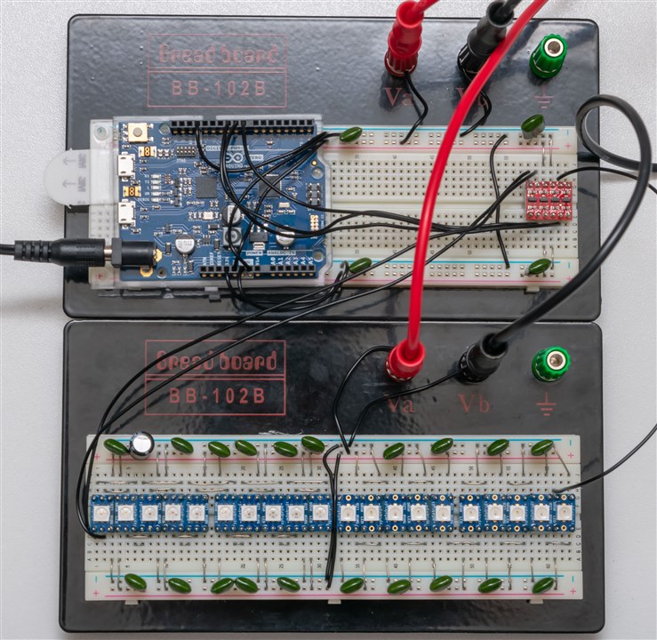
The assembly was completed with some double-sided tape to hold the Arduino Zero to the other breadboard, getting headers onto the level shifter and wiring it all together. It’s time to give it a try …
Two different types of LED displaying the same content, nice and smoothly. I’d call this a success! It better have been, since it was a lot of breadboard work to get here. It’d be a shame if it didn’t …
Testing Another Platform
I wasn’t completely happy with this, because the Arduino Zero isn’t quite ideal in terms of its form factor. I wanted to use something cheap, something with wireless capability, but oddly enough, not an ESP32 (I’m a bit tired of having external USB-UART adapters for them). I could have opted for an ESP32-S3 but some dabbling left me a little underwhelmed, so instead, I’ve got a soft-spot for the Raspberry Pi Pico W now, so I wanted to be sure that it could run on the RP2040 platform.
At this point, I was a bit uncertain, as this FastLED GitHub page actually doesn’t mention the RP2040 as a supported platform at all. But then, in 2022, there was a request to add RP2040 support, connected to a pull request in November that same year. Would it even work?
The easiest way, I thought, was simply to try it. So grabbing a tiny breadboard and a RP2040 based non-wireless Pico that I had lying around, I wired it in, modified the code to match the right pins and …
Surprise, surprise. It worked just fine and this was with the Earl E. Philhower III core as opposed to the official Arduino mBED core. Well, I should have seen this coming, because after some digging, it seems FastLED’s documentation is a bit all-over-the-place, as they have a different docs page which lists many more platforms on which it works – RP2040 included. I only discovered it after doing the tests though … as one usually does.
LED Experiments – Spectrum
If users are trying to build LED arrays for signage or video applications, colour matching is quite critical. Variations between each LED’s wavelength and intensity can lead to solid colours looking “lumpy” and “mosaic” in nature. So I wondered as to how close the spectrum was between the two types of 5050-size LED.
Unfortunately, I do not have access to a professional spectrometer anymore, so I’ve had to make-do with a webcam-based Little Garden Spectrometer calibrated against a CFL tube. It should be fairly accurate when it comes to wavelength, but the linearity of the pass-band is definitely not great – it has some significant ripple as is common with CMOS-type sensors.
Anyhow, the first LED in both strings was measured outputting “white”:

It would seem that there is some small differences in peak wavelength which is not uncommon amongst LEDs even from the same batch, but more significantly, the amount of green output by the two types seem to differ quite a bit with the four-pin one-wire type having “more” green.
It was here that I realised that measuring one really doesn’t give us a great idea of what the rest of the array looks like. But perhaps these measurements shouldn’t be trusted too much either – since temperature of LED can affect the results too and I’m not controlling that, and neither am I controlling potential alignment of the spectrometer slit with the source (although I am using a paper “diffuser” in front of the slit to make it less sensitive to angle). Ideally, I should be using an integrating sphere but alas, I don’t have access to one anymore.
Still worth a shot, I thought –

Considering the janky soldering and the janky spectrometer, normalising for the peak, it would seem that the intensities of the green are within about 10% and of the red is within about 15%, but in reality it is probably better if measured with professional equipment. Some of this variation is likely due to the non-linear response of the CMOS webcam sensor, so I’d say this batch looks quite well matched.

Testing the six-pin, two-wire variety produced a bit more variation both in peak wavelength and intensity. The green seems to suffer the most, with relative intensity changes of about 20% while the red is closer to 15%. Again, perhaps with better soldering and proper equipment, the variations would be somewhat reduced, but this does suggest that this type of LED may be less colour-consistent than the other.

Unfortunately, trying to capture this optically is hard – especially as one set of LEDs is diffused and the other is not.
LED Experiments – Current Consumption
For this experiment, I decided to use the small breadboard and the Raspberry Pi Pico as the main driver, as I really only need to measure one LED, so I didn’t need the rest of the array getting in my way.
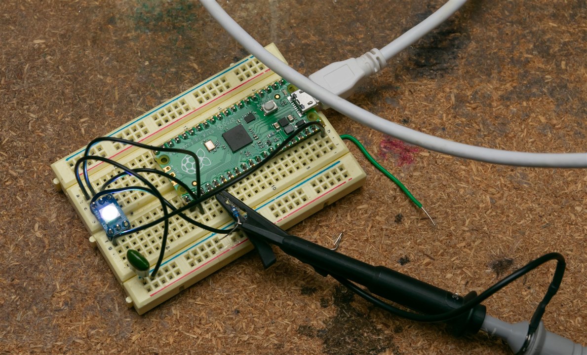
So I wired it up … but notice something is missing? Yes. There’s no level shifter. Gasp! As it turns out, I had mindlessly omitted it … but it still worked which was surprising.
Taking a closer look at the datasheet – it says the following for the 1515050930246 – high level minimum, 0.6 x Vdd. So with a 5V input, as long as the RP2040 is developing more than 3V (under the load of the LED), it would register a high just fine. If the Vdd dips a little, then that’s even better. Likewise for the 1315050930002, high level minimum is 0.7 x Vdd, so thus 3.5V is technically needed. While the RP2040 is a 3.3V device, I guess there is a bit of “tolerance” so it may be unreliable, but I found it to work enough for test purposes. I guess this was just luck!
How much power do the LEDs consume? I decided to find out using my Keithley 2450 SourceMeter at a range of settings when supplied with 5V, including at idle, full brightness white and then by half-steps to the minimum, full brightness red, full brightness green and full brightness blue for both types of 5050 LED.

I was fairly surprised as I thought both 5050-size LEDs would be fairly close, but the 6-pin (two-wire) type actually seems to have twice the current at full brightness, but also the PWM scaling doesn’t seem to be linear like the 4-pin (1-wire) type. The 1-wire type had lower standby current but seemed to have current drive that was a bit lower than the datasheet implied as typical. The 2-wire type had higher than typical standby current but was still within datasheet range, but was pretty much typical on each channel’s current drive.
A common behaviour if the chips are stressed for power is the “dreaded” red light.
LED Experiments – PWM Frequency
One potential downside to such controllable RGB lighting is the presence of flicker due to the use of PWM to dim each LED. The frequency, thus, can be quite an important parameter. To measure this, I dimmed each LED to half-brightness (code = 128) and measured the voltage waveform over a 1-ohm resistance mounted on the ground line with a Rohde & Schwarz MXO4 oscilloscope. The oscillations in this resistance will reveal the PWM characteristics of the LED.

The 6-pin, two-wire type has an impressively high PWM frequency of about 22.45kHz. Thankfully this wasn’t any higher – get to 36kHz or 38kHz and you might start interfering with remote controls (assuming the IR receivers aren’t spectrally selective enough – CFL bulb interference of the past suggests this is a possibility). This does compare well to the 20kHz stated in the datasheet.

The 4-pin, one-wire type measured a PWM frequency 1.043kHz, which was quite a bit less than the 2.5kHz typical listed in the datasheet. I’m not exactly sure why this was the case – I tested this both with WS2811 and WS2812B type selections with no difference.
Regardless, for human viewing, frequencies above about 500Hz are not perceptible at all nor cause any health effects, so that is fine. But for my use with cameras, the risk is that banding may occur with rolling-shutter style cameras depending on how the pixel read-out rate compares with the PWM frequency. For static shutter, as long as I’m taking a photo that’s longer than the period, I should get full illumination, but with exposure variance as some photos may have two PWM “bursts” and others may have just one. Still, these results still seem to support my idea being feasible.
LED Compatibility?
One of the downsides is that I’ve only been able to test the 5050-size LEDs because they’re the ones that will solder to the breakouts. What about the compatibility of the other supplied LEDs?
Looking at Würth’s repository, they helpfully group these single-wire LEDs (1315050930002, 1313210530000, 1312020030000) as being supported by the 24-bit SDK which implies to me that they all use the WS2812B-compatible signalling protocol.
Then there are these two-wire LEDs (1315050930246, 1311610030140) which also use the 24-bit SDK, implying to me that both use the APA102-compatible protocol.
This leaves the final LED – 1312121320437. This one is listed as using the 48-bit SDK and has an interesting protocol. Looking at the datasheet, it is a single-wire type LED, but it has a bypass connection to guard against single-LED failures. It has timings which are compatible with the 24-bit LEDs to within 50ns, but requires sending 16-bits per channel rather than just 8.
I had to dig around for a while to find something that looked like it had these parameters, but I eventually stumbled upon the FastLED post on Reddit announcing the support for WS2816 “High Definition” in v.3.9.12 released nine months ago.

Looking into the code … I found this in the comments:

It has the words I was hoping to hear – WS2812, check! Twice as many 24-bit pixels, check! Even though I don’t have the LEDs soldered, I presume that instantiating the LED string as a WS2816 may well do the trick!
Conclusion
All the hard work so far has been rewarded with a resounding display of multi-coloured light, under my command. I’ve had the chance to delve into making the 5050 LEDs work, but also examining some of their parameters (related to power, PWM frequency and spectra) more closely. In all, I now can see that FastLED will work with my intended platform and know that the LEDs should work just fine with FastLED too. It seems the pieces are starting to fall into place …
Thanks for joining me in this update – I suppose with the clock counting down, it’s time to move on with my ideas and turn them into PCBs and 3D prints. After all, a breadboard is awfully rectilinear for what I want … but how ever will I catch up now with just two weeks remaining? Stay tuned …


